MERCEDES-BENZ G-CLASS SUV 2015 Owners Manual
Manufacturer: MERCEDES-BENZ, Model Year: 2015, Model line: G-CLASS SUV, Model: MERCEDES-BENZ G-CLASS SUV 2015Pages: 274, PDF Size: 31.95 MB
Page 131 of 274
Front sensors
CenterApprox. 40 in (approx.
100 cm from the brush
guard)
CornersApprox. 24 in (approx.
60 cm)
Rear sensors
CenterApprox. 36 in (90 cm) from
the spare wheel
CornersApprox. 32 in (approx.
80 cm)
Minimum distance
CenterApprox. 8 in (approx.
20 cm)
CornersApprox. 8 in (approx.
20 cm)
If there is an obstacle within this range, the
relevant warning displays light up and a warn- ing tone sounds. If the distance falls below
the minimum, the distance may no longer be
shown.
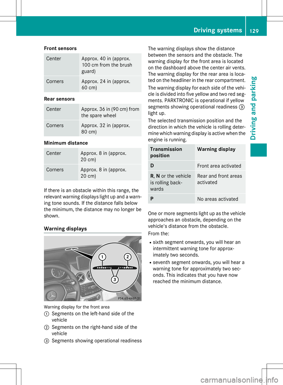
Warning displays
Warning display for the front area :
Segments on the left-hand side of the
vehicle
;Segments on the right-hand side of the
vehicle
=Segments showing operational readiness The warning displays show the distance
between the sensors and the obstacle. The
warning display for the front area is located
on the dashboard above the center air vents.
The warning display for the rear area is loca-
ted on the headliner in the rear compartment.
The warning display for each side of the vehi-
cle is divided into five yellow and two red seg- ments. PARKTRONIC is operational if yellow
segments showing operational readiness =
light up.
The selected transmission position and the
direction in which the vehicle is rolling deter-
mine which warning display is active when the engine is running.
Transmission
positionWarning display
DFront area activated
R ,N or the vehicle
is rolling back- wardsRear and front areas
activated
PNo areas activated
One or more segments light up as the vehicle
approaches an obstacle, depending on the
vehicle's distance from the obstacle.
From the:
R sixth segment onwards, you will hear an
intermittent warning tone for approx-
imately two seconds.
R seventh segment onwards, you will hear a
warning tone for approximately two sec-
onds. This indicates that you have now
reached the minimum distance.
Driving systems129
Driving and pa rking
Z
Page 132 of 274
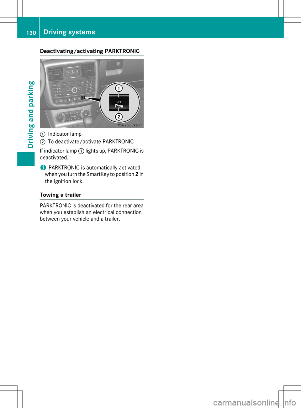
Deactivating/activating PARKTRONIC
:Indicator lamp
;To deactivate/activate PARKTRONIC
If indicator lamp :lights up, PARKTRONIC is
deactivated.
iPARKTRONIC is automatically activated
when you turn the SmartKey to position 2in
the ignition lock.
Towing a trailer
PARKTRONIC is deactivated for the rear area
when you establish an electrical connection
between your vehicle and a trailer.
130Driving syste ms
Driving and parking
Page 133 of 274
Problems with PARKTRONIC
ProblemPossible causes/consequences andMSolutions
Only the red segments
in the PARKTRONIC
warning displays are lit.
You also hear a warning
tone for approximately
two seconds.
PARKTRONIC is deacti-
vated after a few sec-
onds, and the indicator
lamp in the
PARKTRONIC button
lights up.PARKTRONIC has malfunctioned and has switched off.
X If problems persist, have PARKTRONIC checked at a qualified
specialist workshop.
Only the red segments
in the PARKTRONIC
warning displays are lit.
PARKTRONIC is deacti-
vated after a few sec-onds.The PARKTRONIC sensors are dirty or there is interference. X Clean the PARKTRONIC sensors ( Ypage 211).
X Switch the ignition back on.
The problem may be caused by an external source of radio or
ultrasound waves. XSee if PARKTRONIC functions in a different location.
Rear view camera
Important safety notes
The rear view camera is only an aid. It is not a replacement for your attention to your imme-
diate surroundings. You are always responsi-
ble for safe maneuvering and parking. When
maneuvering or parking, make sure that there are no persons, animals or objects in the area in which you are maneuvering.
Under the following circumstances, the rear
view camera will not function, or will function
in a limited manner:
R the rear door is open
R in heavy rain, snow or fog
R at night or in very dark places
R if the camera is exposed to very bright light
R if the area is lit by fluorescent light or LED
lighting (the display may flicker) R
if there is a sudden change in temperature,
e.g. when driving into a heated garage inwinter
R if the camera lens is dirty or obstructed
R if the rear of your vehicle is damaged. In this
event, have the camera position and setting checked at a qualified specialist workshop
Mercedes-Benz recommends that you use
an authorized Mercedes-Benz Center for
this purpose
Driving systems131
Driving and parking
Z
Page 134 of 274
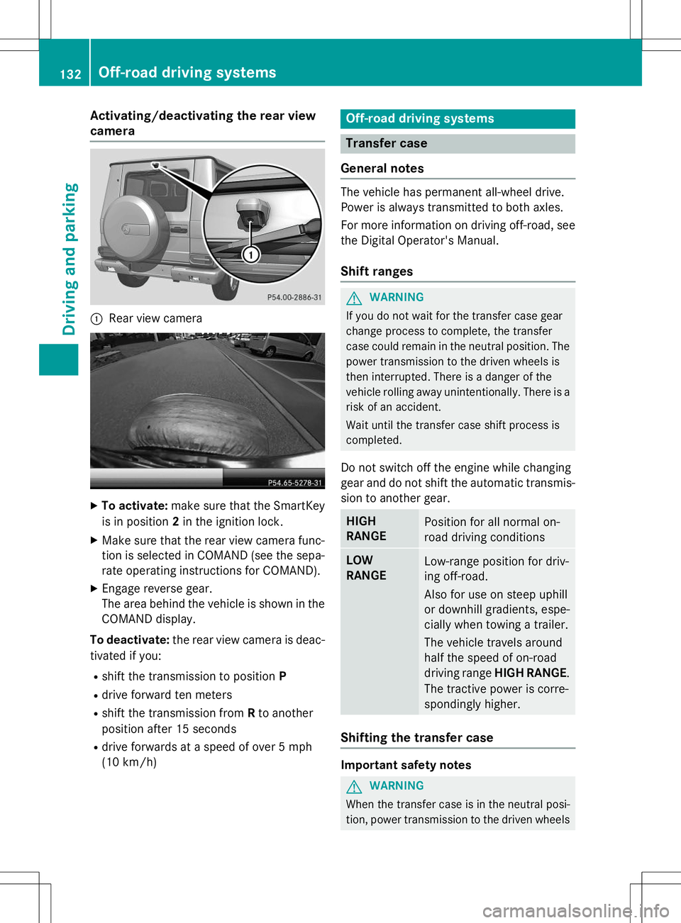
Activating/deactivating the rear view
camera
:Rear view camera
XTo activate: make sure that the SmartKey
is in position 2in the ignition lock.
X Make sure that the rear view camera func-
tion is selected in COMAND (see the sepa-
rate operating instructions for COMAND).
X Engage reverse gear.
The area behind the vehicle is shown in the
COMAND display.
To deactivate: the rear view camera is deac-
tivated if you:
R shift the transmission to position P
R drive forward ten meters
R shift the transmission from Rto another
position after 15 seconds
R drive forwards at a speed of over 5 mph
(10 km/h)
Off-road driving systems
Transfer case
General notes
The vehicle has permanent all-wheel drive.
Power is always transmitted to both axles.
For more information on driving off-road, see the Digital Operator's Manual.
Shift ranges
GWARNING
If you do not wait for the transfer case gear
change process to complete, the transfer
case could remain in the neutral position. The power transmission to the driven wheels is
then interrupted. There is a danger of the
vehicle rolling away unintentionally. There is a
risk of an accident.
Wait until the transfer case shift process is
completed.
Do not switch off the engine while changing
gear and do not shift the automatic transmis-
sion to another gear.
HIGH
RANGEPosition for all normal on-
road driving conditions
LOW
RANGELow-range position for driv-
ing off-road.
Also for use on steep uphill
or downhill gradients, espe-
cially when towing a trailer.
The vehicle travels around
half the speed of on-road
driving range HIGH RANGE .
The tractive power is corre-
spondingly higher.
Shifting the transfer case
Important safety notes
GWARNING
When the transfer case is in the neutral posi-
tion, power transmission to the driven wheels
132Off-road driving systems
Driving and pa rking
Page 135 of 274
is interrupted. As a result, the vehicle could
roll away. There is a risk of an accident.
Secure the vehicle with the parking brake, andon uphill or downhill gradients, also secure it
with a device such as a wheel chock.
Always wait for the gear change process from HIGH RANGE toLOW RANGE and from
LOW RANGE toHIGH RANGE to complete.
Do not switch off the engine while changing
gear and do not shift the automatic transmis-
sion to another gear.
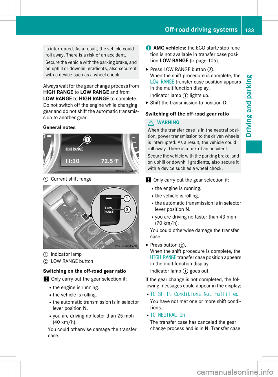
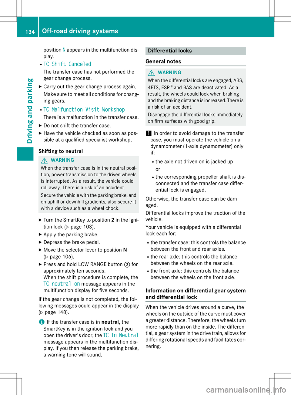
General notes
:Current shift range
:Indicator lamp
;LOW RANGE button
Switching on the off-road gear ratio
!Only carry out the gear selection if:
R the engine is running.
R the vehicle is rolling.
R the automatic transmission is in selector
lever position N.
R you are driving no faster than 25 mph
(40 km/h).
You could otherwise damage the transfercase.
iAMG vehicles: the ECO start/stop func-
tion is not available in transfer case posi- tion LOW RANGE (Y page 105).
X Press LOW RANGE button ;.
When the shift procedure is complete, the
LOW RANGEtransfer case position appears
in the multifunction display.
Indicator lamp :lights up.
X Shift the transmission to position D.
Switching off the off-road gear ratio
GWARNING
When the transfer case is in the neutral posi-
tion, power transmission to the driven wheels
is interrupted. As a result, the vehicle could
roll away. There is a risk of an accident.
Secure the vehicle with the parking brake, and on uphill or downhill gradients, also secure it
with a device such as a wheel chock.
!Only carry out the gear selection if:
R the engine is running.
R the vehicle is rolling.
R the automatic transmission is in selector
lever position N.
R you are driving no faster than 43 mph
(70 km/h).
You could otherwise damage the transfercase.
X Press button ;.
When the shift procedure is complete, the
HIGHRANGEtransfer case position appears
in the multifunction display.
Indicator lamp :goes out.
If the gear change is not completed, the fol-
lowing messages could appear in the display: R
TC Shift Conditions Not Fulfilled
You have not met one or more shift condi-
tions.
R
TC NEUTRAL On
The transfer case has canceled the gear
change process and is in N. Transfer case
Off-road driving systems133
Driving and parking
Z
Page 136 of 274
positionNappears in the multifunction dis-
play.
R
TC Shift Canceled
The transfer case has not performed the
gear change process.
X Carry out the gear change process again.
Make sure to meet all conditions for chang-
ing gears.
R
TC Malfunction Visit Workshop
There is a malfunction in the transfer case.
X Do not shift the transfer case.
X Have the vehicle checked as soon as pos-
sible at a qualified specialist workshop.
Shifting to neutral
GWARNING
When the transfer case is in the neutral posi-
tion, power transmission to the driven wheels
is interrupted. As a result, the vehicle could
roll away. There is a risk of an accident.
Secure the vehicle with the parking brake, and on uphill or downhill gradients, also secure it
with a device such as a wheel chock.
X Turn the SmartKey to position 2in the igni-
tion lock ( Ypage 103).
X Apply the parking brake.
X Depress the brake pedal.
X Move the selector lever to position N
( Y page 106).
X Press and hold LOW RANGE button ;for
approximately ten seconds.
When the shift procedure is complete, the
TC neutral onmessage appears in the
multifunction display for five seconds.
If the gear change is not completed, the fol-
lowing messages could appear in the display( Y page 148).
iIf the transfer case is in neutral, the
SmartKey is in the ignition lock and you
open the driver's door, the
TCInNeutral
message appears in the multifunction dis-
play. If you then release the parking brake, a warning tone will sound.
Differential locks
General notes
GWARNING
When the differential locks are engaged, ABS, 4ETS, ESP ®
and BAS are deactivated. As a
result, the wheels could lock when braking
and the braking distance is increased. There is
a risk of an accident.
Disengage the differential locks immediately
on firm surfaces with good grip.
!In order to avoid damage to the transfer
case, you must operate the vehicle on a
dynamometer (1-axle dynamometer) onlyif:
R the axle not driven on is jacked up or
R the corresponding propeller shaft is dis-
connected and the transfer case differ-
ential lock is engaged.
Otherwise, the transfer case can be dam-aged.
Differential locks improve the traction of the vehicle.
Your vehicle is equipped with a differential
lock each for: R the transfer case: this controls the balance
between the front and rear axles.
R the rear axle: this controls the balance
between the wheels on the rear axle.
R the front axle: this controls the balance
between the wheels on the front axle.
Information on differential gear system
and differential lock
When the vehicle drives around a curve, the
wheels on the outside of the curve must cover
a greater distance. Therefore, the wheels turn more rapidly than on the inside. The differen-
tial, a gear system in the drive train, allows for
differing rotational speeds and facilitates cor- nering.
134Off-road driving systems
Driving and parking
Page 137 of 274
The disadvantage of a differential is that the
wheels that have the least grip, get the most
drive. An example: a wheel of a driven axle is
on a snow-covered surface and therefore
does not have any traction. The differential
sends most of the drive force to this wheel
because the force takes the route of the low-
est resistance. The opposite wheel on this
axle, however, which stands on firm ground
and could therefore allow propulsion,
receives no driving power. 4ETS compen-
sates for this disadvantage. 4ETS provides
good steerability by automatically braking the
spinning wheel. 4ETS provides the wheel on
the firm surface with more drive force, which in turn provides propulsion. ESP ®
and 4ETS are traction systems that are
ideal for road driving and suitable for light off-
road driving. The LOW RANGEoff-road gear
also improves off-road capability.
More challenging off-road conditions require
additional measures such as locking one or
more differential. Your vehicle is equipped
with three differential locks:
R a central differential lock for the transfercase
R a differential lock for the front axle and
R a differential lock for the rear axle
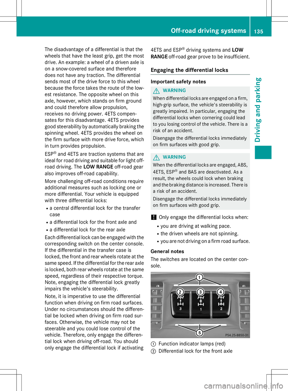
Each differential lock can be engaged with the corresponding switch on the center console.
If the differential in the transfer case is
locked, the front and rear wheels rotate at the same speed. If the differential for the rear axle
is locked, both rear wheels rotate at the same
speed, regardless of their respective torque.
Note, engaging the differential lock greatly
impairs the vehicle's steerability.
Note, it is imperative to use the differential
function when driving on firm road surfaces.
Under no circumstances should the differen-
tial be locked when driving on firm road sur-
faces. Otherwise, the vehicle may not be
steerable and you could lose control of the
vehicle. Therefore, only engage the differen-
tial lock when driving off-road. You should
only engage the differential lock if activating 4ETS and ESP
®
driving systems and LOW
RANGE off-road gear prove to be insufficient.
Engaging the differential locks
Important safety notes
GWARNING
When differential locks are engaged on a firm,
high-grip surface, the vehicle's steerability is
greatly impaired. In particular, engaging the
differential locks when cornering could lead
to you losing control of the vehicle. There is a
risk of an accident.
Disengage the differential locks immediately
on firm surfaces with good grip.
GWARNING
When the differential locks are engaged, ABS,
4ETS, ESP ®
and BAS are deactivated. As a
result, the wheels could lock when braking
and the braking distance is increased. There is
a risk of an accident.
Disengage the differential locks immediately
on firm surfaces with good grip.
!Only engage the differential locks when:
R you are driving at walking pace.
R the driven wheels are not spinning.
R you are not driving on a firm road surface.
General notes
The switches are located on the center con- sole.
:Function indicator lamps (red)
;Differential lock for the front axle
Off-road driving systems135
Driving and parking
Z
Page 138 of 274
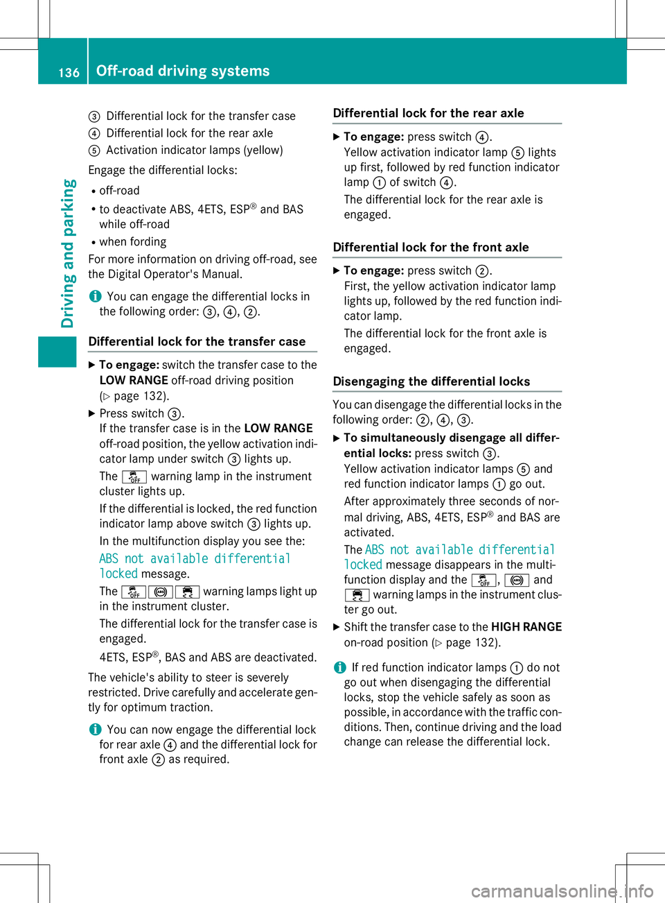
=Differential lock for the transfer case
?Differential lock for the rear axle
AActivation indicator lamps (yellow)
Engage the differential locks: R off-road
R to deactivate ABS, 4ETS, ESP ®
and BAS
while off-road
R when fording
For more information on driving off-road, see the Digital Operator's Manual.
iYou can engage the differential locks in
the following order: =,? ,; .
Differential lock for the transfer case
X
To engage: switch the transfer case to the
LOW RANGE off-road driving position
( Y page 132).
X Press switch =.
If the transfer case is in the LOW RANGE
off-road position, the yellow activation indi- cator lamp under switch =lights up.
The å warning lamp in the instrument
cluster lights up.
If the differential is locked, the red function indicator lamp above switch =lights up.
In the multifunction display you see the:
ABS not available differential
lockedmessage.
The å!÷ warning lamps light up
in the instrument cluster.
The differential lock for the transfer case is
engaged.
4ETS, ESP ®
, BAS and ABS are deactivated.
The vehicle's ability to steer is severely
restricted. Drive carefully and accelerate gen-
tly for optimum traction.
iYou can now engage the differential lock
for rear axle ?and the differential lock for
front axle ;as required.
Differential lock for the rear axle
X
To engage: press switch ?.
Yellow activation indicator lamp Alights
up first, followed by red function indicator
lamp :of switch ?.
The differential lock for the rear axle is
engaged.
Differential lock for the front axle
X To engage: press switch ;.
First, the yellow activation indicator lamp
lights up, followed by the red function indi- cator lamp.
The differential lock for the front axle is
engaged.
Disengaging the differential locks
You can disengage the differential locks in the
following order: ;,? ,= .
X To simultaneously disengage all differ-
ential locks: press switch=.
Yellow activation indicator lamps Aand
red function indicator lamps :go out.
After approximately three seconds of nor-
mal driving, ABS, 4ETS, ESP ®
and BAS are
activated.
The
ABSnotavailabledifferential
lockedmessage disappears in the multi-
function display and the å,! and
÷ warning lamps in the instrument clus-
ter go out.
X Shift the transfer case to the HIGH RANGE
on-road position ( Ypage 132).
iIf red function indicator lamps :do not
go out when disengaging the differential
locks, stop the vehicle safely as soon as
possible, in accordance with the traffic con- ditions. Then, continue driving and the load
change can release the differential lock.
136Off-road driving systems
Driving an d parking
Page 139 of 274
Towing a trailer
Notes on towing a trailer
Important safety notes
GWARNING
If you rest your foot on the brake pedal while
driving, the braking system can overheat. This increases the stopping distance and can even
cause the braking system to fail. There is a
risk of an accident.
Never use the brake pedal as a footrest. Never
depress the brake pedal and the accelerator
pedal at the same time.
GWARNING
When the vehicle/trailer combination begins
to lurch, you could lose control of it. The vehi- cle/trailer combination could even rollover.
There is a risk of an accident.
On no account should you attempt to
straighten up the vehicle/trailer combination
by increasing the speed. Reduce vehicle
speed and do not countersteer. Apply the
brake as necessary.
GWARNING
If you install a ball coupling other than the one
delivered with the vehicle, the trailer tow hitch and the rear axle may be overloaded. This
applies especially if the ball coupling in ques- tion is longer or angled differently. This could seriously impair the driving characteristics
and the trailer can come loose. There is a risk
of an accident.
Only install the ball coupling delivered with
the vehicle or a ball coupling that is designed
to meet your trailer towing requirements. Do
not modify the ball coupling or the trailer tow hitch.
GWARNING
If the ball coupling is not installed correctly or not secured with the bolt provided and the
corresponding spring cotter, the trailer may
come loose. There is a risk of an accident.
Always install and secure the ball coupling asdescribed. Before every journey, ensure that
the ball coupling is secured with the bolt and
the corresponding spring cotter.
Please observe the manufacturer's operating instructions for the trailer coupling if a
detachable trailer coupling is used.
Exceeding the maximum permissible nose-
weight may cause damage to the following: R your vehicle
R the trailer
R the ball coupling
R trailer tow hitch
The vehicle/trailer combination could
become unstable.
If the noseweight used is lower than the min- imum permissible noseweight, the vehicle/
trailer combination could also become unsta-ble.
To avoid hazardous situations:
R make sure to check the noseweight before
each journey
R use a drawbar noseweight as close as pos-
sible to the maximum noseweight
R do not exceed the maximum permissible
noseweight
R do not use a noseweight lower than the
minimum permissible trailer drawbar nose-
weight
When backing up the vehicle towards the
trailer, make sure there is nobody between
the trailer and the vehicle.
The applicable permissible values, which
must not be exceeded, can be found:
R in your vehicle documents
R on the type plate of the trailer tow hitch and
trailer
R on the vehicle identification plate
Couple and uncouple the trailer carefully. If
you do not couple the trailer to the towing
vehicle correctly, the trailer could become
detached.
Towing a trailer137
Driving an d parking
Z
Page 140 of 274
Make sure that the following values are not exceeded:
R the permissible trailer drawbar noseweight
R the permissible trailer load
R the permissible rear axle load of the towing
vehicle
R the maximum permissible gross vehicle
weight of both the towing vehicle and thetrailer
When towing a trailer, your vehicle's handling
characteristics will be different in comparison with when driving without a trailer.
The vehicle/trailer combination:
R is heavier
R is restricted in its acceleration and gradi-
ent-climbing capability
R has an increased braking distance
R is affected more by strong crosswinds
R demands more sensitive steering
R has a larger turning radius
This could impair the handling characteris-
tics. Adapt your driving style accordingly.
Maintain a safe distance. Drive carefully.
When towing a trailer, always adjust your
speed to the current road and weather con-
ditions. Do not exceed the maximum permis- sible speed for your vehicle/trailer combina-tion.
You will find the values approved by the man-
ufacturer on the vehicle identification plates
and those for the towing vehicle in the "Tech- nical data" section ( Ypage 268).
Driving tips
X
On long and steep downhill gradients,
select shift range 1,2 or 3(Y page 107) in
good time.
iThis also applies if you have activated
cruise control or SPEEDTRONIC.
X If necessary, shift the transfer case to LOW
RANGE (Y page 132).
This will use the braking effect of the
engine, so that less braking will be required to maintain the speed. This relieves the
load on the brake system and prevents the
brakes from overheating and wearing too
quickly. If you need additional braking,
depress the brake pedal repeatedly rather
than continuously.
The maximum permissible speed for vehicle/
trailer combinations depends on the type of
trailer. Before beginning the journey, check
the trailer's documents to see what the max- imum permissible speed is. Observe the
legally prescribed maximum speed in the rel-evant country.
For certain Mercedes-Benz vehicles, the max-
imum permissible rear axle load is increased
when towing a trailer. Refer to the "Technical
data" section to find out whether this applies to your vehicle. If you utilize any of the added
maximum rear axle load when towing a trailer, the vehicle/trailer combination may not
exceed a maximum speed of 60 mph
(100 km/h) for reasons concerning the oper-ating permit. This also applies in countries in
which the permissible maximum speed for
vehicle/trailer combinations is above 60 mph (100 km/h).
When towing a trailer, your vehicle's handling
characteristics will be different in comparison
to when driving without a trailer and it will
consume more fuel.
On long and steep downhill gradients, you
must select shift range 1,2 or 3in good time.
iThis also applies if you have activated
cruise control or DISTRONIC PLUS.
This will use the braking effect of the engine,
so that less braking will be required to main-
tain the speed. This relieves the load on the
brake system and prevents the brakes from
overheating and wearing too quickly. If you
need additional braking, depress the brake
pedal repeatedly rather than continuously.
138Towing a trailer
Driving and parking