lights MERCEDES-BENZ G500 2002 W463 Owner's Manual
[x] Cancel search | Manufacturer: MERCEDES-BENZ, Model Year: 2002, Model line: G500, Model: MERCEDES-BENZ G500 2002 W463Pages: 385, PDF Size: 30.37 MB
Page 32 of 385
29 Central locking system
Te ch n i c a l
data Instruments
and controlsOperationDrivingInstrument
cluster displayPractical hints Car care Index Central locking system
Radio frequency and infrared remote control
The electronic key has an integrated radio frequency
and infrared remote control.
Due to the extended operational range of the remote
control, it could be possible to unintentionally lock or
unlock the vehicle by pressing the transmit button. If
one of the transmit buttons is pressed, the battery check
lamp lights up briefly – indicating that the batteries are
in order. See page 343 for checking batteries.
The vehicle doors, tailgate and fuel filler flap can be
centrally locked and unlocked via remote control.
Opening and closing the windows can only be done with
the infrared portion of the remote control. Aim
transmitter eye at the receiver of the driver’s door (6),
press and hold transmit button Œ or ‹,
seepage32.
If the electronic key is inserted in the starter switch, the
vehicle cannot be locked or unlocked with the remote
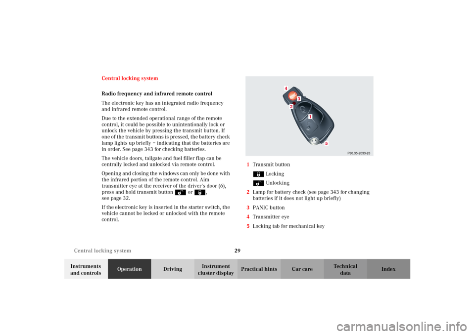
control.1Transmit button
‹ Locking
ΠUnlocking
2Lamp for battery check (see page 343 for changing
batteries if it does not light up briefly)
3PANIC button
4Transmitter eye
5Locking tab for mechanical key
P80.35-2033-26
2
1
4
3
5
J_G463.book Seite 29 Mittwoch, 19. September 2001 8:06 08
Page 55 of 385
52 Seats
Te ch n i c a l
data Instruments
and controlsOperationDrivingInstrument
cluster displayPractical hints Car care Index
Seat heater, front
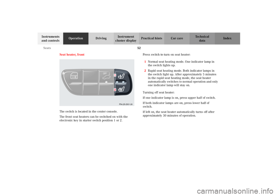
The switch is located in the center console.
The front seat heaters can be switched on with the
electronic key in starter switch position 1 or 2.Press switch to turn on seat heater:
1Normal seat heating mode. One indicator lamp in
the switch lights up.
2Rapid seat heating mode. Both indicator lamps in
the switch light up. After approximately 5 minutes
in the rapid seat heating mode, the seat heater
autom atically s witches to n ormal o peration an d on ly
one indicator lamp will stay on.
Turning off seat heater:
If one indicator lamp is on, press upper half of switch.
If both indicator lamps are on, press lower half of
switch.
If left on, the seat heater automatically turns off after
approximately 30 minutes of operation.
P54.25-2501-26
J_G463.book Seite 52 Mittwoch, 19. September 2001 8:06 08
Page 57 of 385
54 Seats
Te ch n i c a l
data Instruments
and controlsOperationDrivingInstrument
cluster displayPractical hints Car care Index
Seat heater, rear
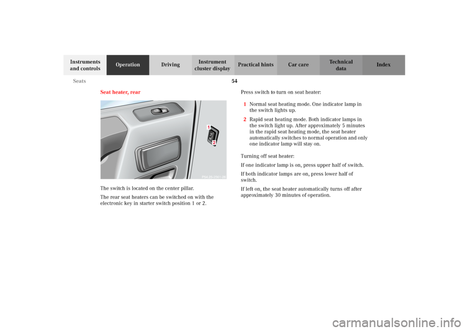
The switch is located on the center pillar.
The rear seat heaters can be switched on with the
electronic key in starter switch position 1 or 2.Press switch to turn on seat heater:
1Normal seat heating mode. One indicator lamp in
the switch lights up.
2Rapid seat heating mode. Both indicator lamps in
the switch light up. After approximately 5 minutes
in the rapid seat heating mode, the seat heater
autom atically s witches to n ormal o peration an d on ly
one indicator lamp will stay on.
Turning off seat heater:
If one indicator lamp is on, press upper half of switch.
If both indicator lamps are on, press lower half of
switch.
If left on, the seat heater automatically turns off after
approximately 30 minutes of operation.
122561
J_G463.book Seite 54 Mittwoch, 19. September 2001 8:06 08
Page 133 of 385
130 Exterior lamp switch
Te ch n i c a l
data Instruments
and controlsOperationDrivingInstrument
cluster displayPractical hints Car care Index
Headlamp mode
Manual headlamp mode
The low beam headlamps and parking lamps can be
switched on and off with the exterior lamp switch. For
exterior lamp switch, see above.
Note:
With the daytime running lamp mode activated and the
engine running, the low beam headlamps cannot be
switched off manually.Automat ic headlamp mode
Turn exterior lamp switch to positionU.
•Electronic key in starter switch position 1:
The parking lamps switch on and off automatically
depending on the brightness of the ambient light.
•Electronic key in starter switch position 2 and the
engine running:
The low beam headlamps and parking lamps are
switched on and off automatically depending on the
brightness of the ambient light.
The low beam headlamps and parking lamps can
still be switched on and off manually using the
exterior lamp switch.
Note:
With the daytime running lamp mode activated, the low
beam headlamps cannot be switched off manually.
The headlamps will not be automatically switched on
under foggy conditions.
Front fog lamps and rear fog lamp cannot be switched
on manually with exterior lamp switch in positionU.
To activate the fog lamps turn exterior switch to
positionB.
Wa r n i n g !
The driver is responsible for the operation of the
vehicle’s lights at all times. The automatic
headlamp feature is only an aid to the driver.
Switch on the vehicle lights by hand when driving
or traffic conditions require you to do so.
J_G463.book Seite 130 Mittwoch, 19. September 2001 8:06 08
Page 185 of 385
182 Interior equipment
Te ch n i c a l
data Instruments
and controlsOperationDrivingInstrument
cluster displayPractical hints Car care Index
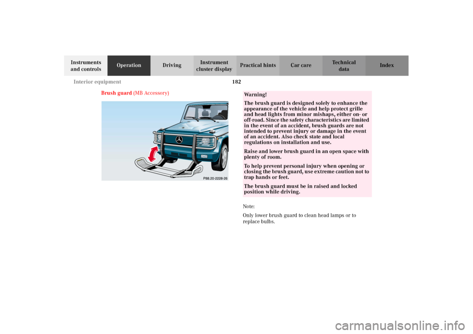
Brush guard (MB Accessory)
Note:
Only lower brush guard to clean head lamps or to
replace bulbs.
Wa r n i n g !
The brush guard is designed solely to enhance the
appearance of the vehicle and help protect grille
and head lights from minor mishaps, either on- or
off-road. Since the safety characteristics are limited
in the event of an accident, brush guards are not
intended to prevent injury or damage in the event
of an accident. Also check state and local
regulations on installation and use.Raise and lower brush guard in an open space with
plenty of room.To help prevent personal injury when opening or
c los in g the b rush gua rd, us e extrem e ca uti on n ot to
trap hands or feet.The brush guard must be in raised and locked
position while driving.
J_G463.book Seite 182 Mittwoch, 19. September 2001 8:06 08
Page 211 of 385
208 Automatic transmission
Te ch n i c a l
data Instruments
and controlsOperationDrivingInstrument
cluster displayPractical hints Car care Index
Driving
The selector lever is automatically locked while in
position “P”. To move the selector lever out of
position “P”, the service brake pedal must be firmly
depressed before the shift lock will release.
Shif t s elector leve r to t he d es ir ed pos ition on ly when t he
engine is idling normally and the service brake is
applied. Do not release the brake until ready to drive.
The vehicle may otherwise start creeping when the
selector lever is in drive or reverse position.Important!
After selecting any driving position from “N” or “P”,
wait a moment to allow the gear to fully engage before
accelerating, especially when the engine is cold.
Accelerator position
Partial throttle = early upshifting = normal acceleration
Full throttle = later upshifting = rapid acceleration
Kickdown (depressing the accelerator beyond full
throttle) = downshifting to a lower gear = maximum
ac celeration . On ce t he d es ire d s peed is attain ed , eas e up
on the accelerator – the transmission shifts up again.
Stopping
For brief stops, e.g. at traffic lights, leave the
transmission in gear and hold vehicle with the service
brake.
For longer stops with the engine idling, shift into “N”
or “P” and hold the vehicle with the service brake.
When stopping the vehicle on an uphill gradient, do not
hold it with the accelerator, use the brake. This avoids
unnecessary transmission heat build up.
Wa r n i n g !
It is dangerous to shift the selector lever out of “P”
or “N” if the engine speed is higher than idle speed.
If your foot is not firmly on the brake pedal, the
vehicle could accelerate quickly forward or in
reverse. You could lose control of the vehicle and
hit someone or something. Only shift into gear
when the engine is idling normally and when your
right foot is firmly on the brake pedal.
O n s l i p p e ry ro a d s u rfa c es , n eve r d ow n s h i f t i n o rd e r
to obtain braking action. This could result in drive
wheel slip and reduced vehicle control. Your
vehicle’s ABS will not prevent this type of loss of
control.
J_G463.book Seite 208 Mittwoch, 19. September 2001 8:06 08
Page 273 of 385
270 Malfunction and indicator lamps
Te ch n i c a l
data Instruments
and controlsOperation DrivingInstrument
cluster displayPractical hints Car care Index
Electronic stability program (ESP) — warning lamp
The yellow ESP warning lamp in the
speedometer dial comes on with the
electronic key in starter switch position 2.
It should go out with engine running.
If the ESP malfunction indicator lamp remains
illuminated with the engine running, a malfunction has
been detected in the system. Pressing the accelerator
pedal will require greater effort. Only partial engine
output will be available.
With the ESP malfunctioning, the abs, BAS, EBB and
4-ETS are also switched off.
See electronic stability program (ESP) on page 243 if the
warning lamp lights up or flashes when the vehicle is
moving.
Note:
If the transfer case differential lock is engaged the ESP
warning lamp comes on and the ESP, ABS, BAS and
4-ETS are switched off. There is no malfunction in the
system.Seat belt nonusage warning lamp
With the electronic key in starter switch
position 2, the seat belt nonusage warning
lamp comes on, and a warning sounds for a
short time if the drivers seat belt is not fastened.
After starting the engine, the seat belt nonusage
warning lamp blinks for a brief period to remind the
driver and passengers to fasten seat belts.
J_G463.book Seite 270 Mittwoch, 19. September 2001 8:06 08
Page 286 of 385
283 Malfunction and warning messages
Te ch n i c a l
data Instruments
and controlsOperation DrivingInstrument
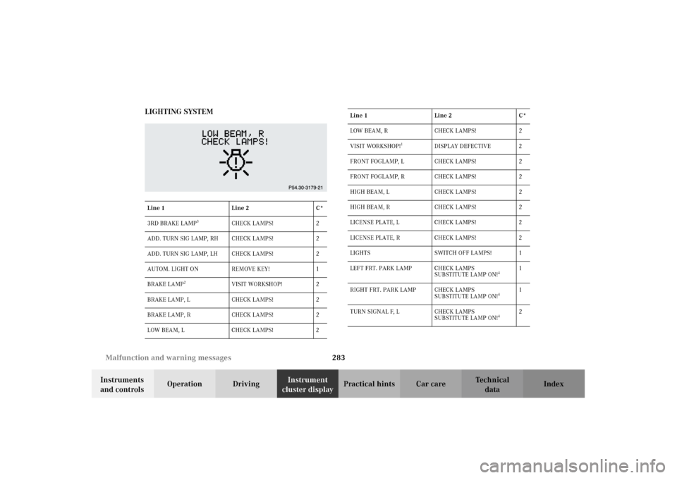
cluster displayPractical hints Car care Index LIGHTING SYSTEM
Line 1 Line 2 C*
3RD BRAKE LAMP
3
CHECK LAMPS! 2
ADD. TURN SIG LAMP, RH CHECK LAMPS! 2
ADD. TURN SIG LAMP, LH CHECK LAMPS! 2
AUTOM. LIGHT ON REMOVE KEY! 1
BRAKE LAMP
2
VISIT WORKSHOP! 2
BRAKE LAMP, L CHECK LAMPS! 2
BRAKE LAMP, R CHECK LAMPS! 2
LOW BEAM, L CHECK LAMPS! 2
LOW BEAM, R CHECK LAMPS! 2
VISIT WORKSHOP!
1
DISPLAY DEFECTIVE 2
FRONT FOGLAMP, L CHECK LAMPS! 2
FRONT FOGLAMP, R CHECK LAMPS! 2
HIGH BEAM, L CHECK LAMPS! 2
HIGH BEAM, R CHECK LAMPS! 2
LICENSE PLATE, L CHECK LAMPS! 2
LICENSE PLATE, R CHECK LAMPS! 2
LIGHTS SWITCH OFF LAMPS! 1
LEFT FRT. PARK LAMP CHECK LAMPS
SUBSTITUTE LAMP ON!
4
1
RIGHT FRT. PARK LAMP CHECK LAMPS
SUBSTITUTE LAMP ON!
4
1
TURN SIGNAL F, L CHECK LAMPS
SUBSTITUTE LAMP ON!
4
2 Line 1 Line 2 C*
J_G463.book Seite 283 Mittwoch, 19. September 2001 8:06 08
Page 325 of 385
322 Jump starting
Te ch n i c a l
data Instruments
and controlsOperation DrivingInstrument
cluster displayPractical hintsCar care Index
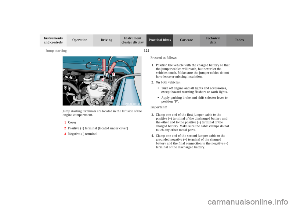
Jump startin g term in als ar e located in t he lef t s id e of t he
engine compartment.
1Cover
2Positive (+) terminal (located under cover)
3Negative (-) terminalProceed as follows:
1. Position the vehicle with the charged battery so that
the jumper cables will reach, but never let the
vehicles touch. Make sure the jumper cables do not
have loose or missing insulation.
2. On both vehicles:
•Turn off engine and all lights and accessories,
except hazard warning flashers or work lights.
•Apply parking brake and shift selector lever to
position “P”.
Important!
3. Clamp one end of the first jumper cable to the
positive (+) terminal of the discharged battery and
the other end to the positive (+) terminal of the
charged battery. Make sure the cable clamps do not
touch any other metal parts.
4. Clamp one end of the second jumper cable to the
grounded negative (–) terminal of the charged
battery and the final connection to the negative (–)
terminal of the discharged battery.
J_G463.book Seite 322 Mittwoch, 19. September 2001 8:06 08
Page 346 of 385
343 Electronic main key
Te ch n i c a l
data Instruments
and controlsOperation DrivingInstrument
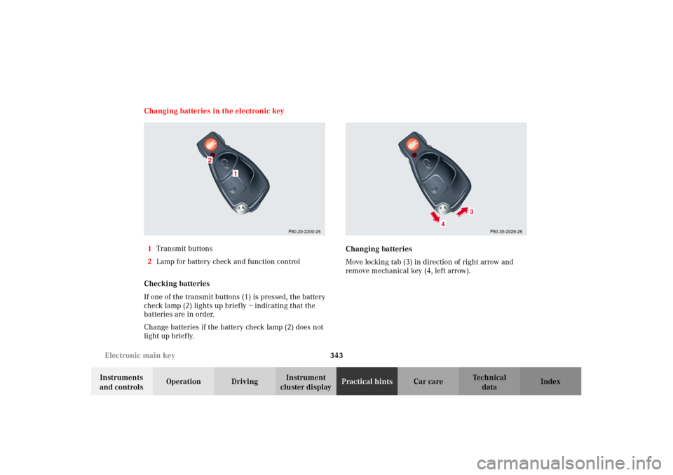
cluster displayPractical hintsCar care Index Changing batteries in the electronic key
1Transmit buttons
2Lamp for battery check and function control
Checking batteries
If one of the transmit buttons (1) is pressed, the battery
check lamp (2) lights up briefly – indicating that the
batteries are in order.
Change batteries if the battery check lamp (2) does not
light up briefly.Changing batteries
Move locking tab (3) in direction of right arrow and
remove mechanical key (4, left arrow).
P80.20-2200-26
1
2
P80.35-2028-26
4
3
J_G463.book Seite 343 Mittwoch, 19. September 2001 8:06 08