dimensions MERCEDES-BENZ GL-Class 2016 X166 User Guide
[x] Cancel search | Manufacturer: MERCEDES-BENZ, Model Year: 2016, Model line: GL-Class, Model: MERCEDES-BENZ GL-Class 2016 X166Pages: 462, PDF Size: 10.44 MB
Page 271 of 462
XDetach the trailer cable and decouple the
trailer.
XSwitch off the engine.
Permissible trailer loads and drawbar
loads
Weight specifications
Maximum permissible gross vehicle
weight rating
The gross trailer weight is calculated by add-
ing the weight of the trailer to the weight of
the load and equipment on the trailer.
You will find installing dimensions and loads
under "Technical data" (
Ypage 457).
Permissible noseweight
You will find installing dimensions and loads
under "Technical data" (
Ypage 457).
Loading a trailer
RWhen loading the trailer, make sure that
neither the permissible gross weight of the trailer nor the gross vehicle weight is
exceeded. The permissible gross vehicle
weight is indicated on the identification
plate on the B-pillar on the driver's side of
the vehicle.
You can find the maximum permissible val-
ues on the type plates of your vehicle and
the trailer. When calculating how much
weight the vehicle and trailer may carry,
pay attention to the respective lowest val-
ues.
RThe trailer drawbar load on the ball coupling
must be added to the rear axle load to avoidexceeding the permissible gross axle
weight. The permissible gross vehicle
weight is indicated on the identification
plate on the B-pillar on the driver's side of
the vehicle.
iMercedes-Benz recommends a trailer
load where the trailer drawbar noseweight accounts for 8% to 15% of the trailer's per-
missible gross weight.
iThe weight of additional accessories, pas-
sengers, and cargo reduces the permissi-
ble trailer load and drawbar load for your
vehicle.
Checking the vehicle and trailer weight
RTo check that the weights of the towing
vehicle and the trailer comply with the max-
imum permissible values, have the vehicle/
trailer combination (including the driver,
passengers, and cargo with a fully laden
trailer) weighed on a calibrated weigh-
bridge.
RCheck the gross axle weight rating of the
front and rear axles, the gross weight of the trailer and trailer drawbar load.
Removing the ball coupling
XRemove the spring cotter.
XRemove the bolt from the ball coupling
recess.
XRemove the ball coupling from the ball cou-
pling recess.
XClean the ball coupling if it is dirty.
XStow the ball coupling so that it cannot be
thrown around.
Observe the loading guidelines (
Ypage 340)
and the safety notes regarding stowage
spaces (
Ypage 341).
Information on cleaning and care of the trailer
tow hitch (
Ypage 381).
Trailer power supply
!
You can connect accessories with a max-
imum power consumption of 240 W to the
permanent power supply.
You must not charge a trailer battery using
the power supply.
The trailer socket of your vehicle is equipped
at the factory with a permanent power supply.
Towing a trailer269
Driving an d parking
Z
Page 411 of 462
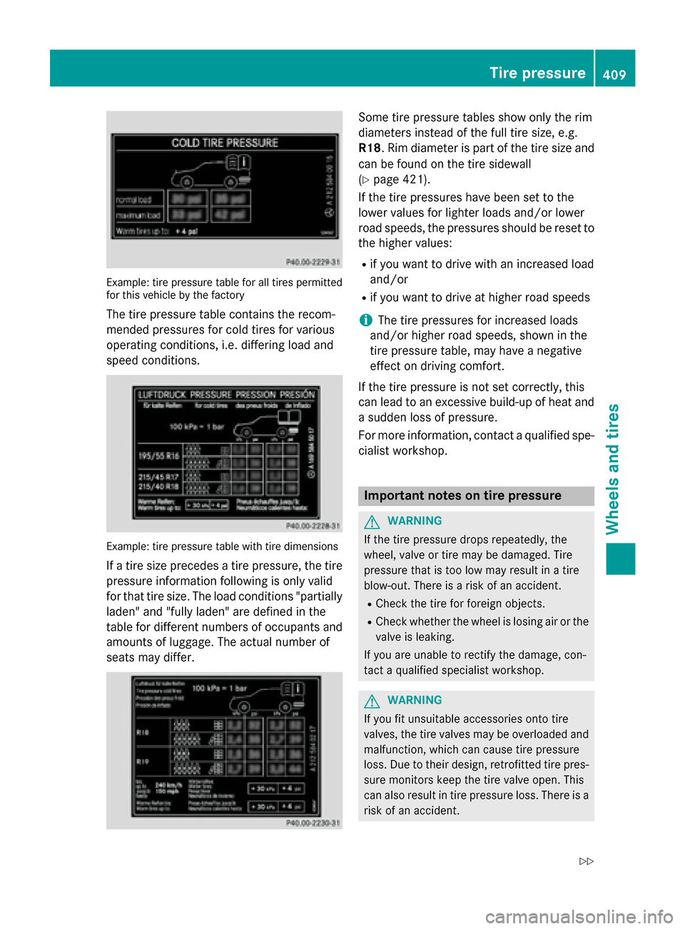
Example: tire pressure table for all tires permitted
for this vehicle by the factory
The tire pressure table contains the recom-
mended pressures for cold tires for various
operating conditions, i.e. differing load and
speed conditions.
Example: tire pressure table with tire dimensions
If a tire size precedes a tire pressure, the tire
pressure information following is only valid
for that tire size. The load conditions "partially
laden" and "fully laden" are defined in the
table for different numbers of occupants and
amounts of luggage. The actual number of
seats may differ.
Some tire pressure tables show only the rim
diameters instead of the full tire size, e.g.
R18. Rim diameter is part of the tire size and
can be found on the tire sidewall
(
Ypage 421).
If the tire pressures have been set to the
lower values for lighter loads and/or lower
road speeds, the pressures should be reset to
the higher values:
Rif you want to drive with an increased load
and/or
Rif you want to drive at higher road speeds
iThe tire pressures for increased loads
and/or higher road speeds, shown in the
tire pressure table, may have a negative
effect on driving comfort.
If the tire pressure is not set correctly, this
can lead to an excessive build-up of heat and
a sudden loss of pressure.
For more information, contact a qualified spe-
cialist workshop.
Important notes on tire pressure
GWARNING
If the tire pressure drops repeatedly, the
wheel, valve or tire may be damaged. Tire
pressure that is too low may result in a tire
blow-out. There is a risk of an accident.
RCheck the tire for foreign objects.
RCheck whether the wheel is losing air or the valve is leaking.
If you are unable to rectify the damage, con-
tact a qualified specialist workshop.
GWARNING
If you fit unsuitable accessories onto tire
valves, the tire valves may be overloaded and
malfunction, which can cause tire pressure
loss. Due to their design, retrofitted tire pres- sure monitors keep the tire valve open. This
can also result in tire pressure loss. There is a
risk of an accident.
Tire pressure409
Wheels and tires
Z
Page 429 of 462
Treadwear indicators
Narrow bars (tread wear bars) that are dis-
tributed over the tire tread. If the tire tread is
level with the bars, the wear limit ofáin
(1.6 mm) has been reached.
Occupant distribution
The distribution of occupants in a vehicle at
their designated seating positions.
Total load limit
Nominal load and luggage load plus 68 kg
(150 lbs) multiplied by the number of seats in
the vehicle.
Changing a wheel
Flat tire
The "Breakdown assistance" section
(
Ypage 387) contains information and notes
on how to deal with a flat tire. Information on
driving with MOExtended tires in the event of
a flat tire can be found under "MOExtended
tires (tires with run-flat characteristics"
(
Ypage 387).
Vehicles with an emergency spare wheel:
in the event of a flat tire, mount the emer-
gency spare wheel according to the descrip-
tion under "Mounting a wheel" (
Ypage 428).
Rotating the wheels
GWARNING
Interchanging the front and rear wheels may
severely impair the driving characteristics if
the wheels or tires have different dimensions. The wheel brakes or suspension components
may also be damaged. There is a risk of acci-
dent.
Rotate front and rear wheels only if the wheels and tires are of the same dimensions.
!On vehicles equipped with a tire pressure
monitor, electronic components are loca-
ted in the wheel. Tire-mounting tools should not be used
near the valve. This could damage the elec-
tronic components.
Only have tires changed at a qualified spe-
cialist workshop.
Always observe the instructions and safety
notes in the "Mounting a wheel" section
(
Ypage 428).
The wear patterns on the front and rear tires
differ, depending on the operating conditions.
Rotate the wheels before a clear wear pattern
has formed on the tires. Front tires typically
wear more on the shoulders and the rear tires
in the center.
On vehicles that have the same size front and
rear wheels, you can rotate the wheels
according to the intervals in the tire manu-
facturer's warranty book in your vehicle docu-
ments. If no warranty book is available, the
tires should be rotated every 3,
000 to
6,000 miles (5,000 to 10,000 km). Depending on tire wear, this may be required earlier. Do
not change the direction of wheel rotation.
Clean the contact surfaces of the wheel and
the brake disc thoroughly every time a wheel
is rotated. Check the tire pressure and, if nec-
essary, restart the tire pressure loss warning
system or the tire pressure monitor.
Direction of rotation
Tires with a specified direction of rotation
have additional benefits, e.g. if there is a risk
of hydroplaning. These advantages can only
be gained if the tires are installed correspond-
ing to the direction of rotation.
An arrow on the sidewall of the tire indicates
its correct direction of rotation.
Storing wheels
Store wheels that are not being used in a cool,
dry and preferably dark place. Protect the
tires from oil, grease, gasoline and diesel.
Changing a wheel427
Wheels and tires
Z
Page 440 of 462
GL 63 AMG 4MATIC
Summer tires
R 21
TiresAlloy wheels
BA: 295/40 ZR 21 111 Y XL3BA: 10.0 J x 21 H2
Wheel offset: 1.81 in (46 mm)
Winter tires
R 20
TiresAlloy wheels
BA: 275/45 R 20 110 V XL M+SiBA: 9.0 J x 20 H2
Wheel offset: 1.61 in (41 mm)
Emergency spare wheel
Important safety notes
GWARNING
The wheel or tire size as well as the tire type of the spare wheel or emergency spare wheel
and the wheel to be replaced may differ.
Mounting an emergency spare wheel may
severely impair the driving characteristics.
There is a risk of an accident.
To avoid hazardous situations:
Radapt your driving style accordingly and
drive carefully.
Rnever mount more than one spare wheel or
emergency spare wheel that differs in size.
Ronly use a spare wheel or emergency spare
wheel of a different size briefly.
Rdo not switch ESP®off.
Rhave a spare wheel or emergency spare
wheel of a different size replaced at the
nearest qualified specialist workshop.
Observe that the wheel and tire dimensions
as well as the tire type must be correct.
!AMG vehicles with "Minispare" emer-
gency spare wheel: use the "Minispare" emergency spare wheel
only on the rear
axle . If you mount the "Minispare" emer-
gency spare wheel on the front axle, this
could result in damage to the brake system.
If a tire on the front axle is defective, an
intact wheel from the rear axle must first be
replaced with the "Minispare" emergency
spare wheel. The faulty wheel on the front
axle may only then be replaced by the
undamaged wheel from the rear axle.
Make sure to note the placard on the
"Minispare" emergency spare wheel.
When using an emergency spare wheel or
spare wheel of a different size, you must not
exceed the maximum speed of 50 mph
(80 km/h).
Snow chains must not be mounted on emer-
gency spare wheels.
General notes
Mounting the emergency spare wheel is
described under "Mounting a wheel"
(
Ypage 428).
You should regularly check the pressure of
the emergency spare wheel, particularly prior
to long trips, and correct the pressure as nec-
3Use of snow chains not permitted. Observe the notes in the "Snow chains" section.
438Emergency spare wheel
Wheels and tires
Page 456 of 462
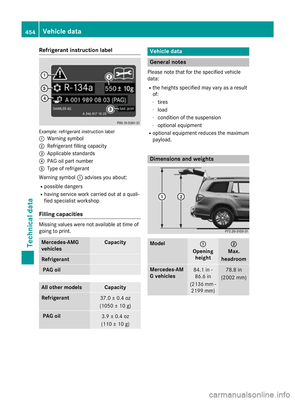
Refrigerant instruction label
Example: refrigerant instruction label
:
Warning symbol
;Refrigerant filling capacity
=Applicable standards
?PAG oil part number
AType of refrigerant
Warning symbol :advises you about:
Rpossible dangers
Rhaving service work carried out at a quali-
fied specialist workshop
Filling capacities
Missing values were not available at time of
going to print.
Mercedes‑AMG
vehiclesCapacity
Refrigerant
PAG oil
All other modelsCapacity
Refrigerant37.0 ± 0.4 oz
(1050 ± 10 g)
PAG oil3.9 ± 0.4 oz
(110 ± 10 g)
Vehicle data
General notes
Please note that for the specified vehicle
data:
Rthe heights specified may vary as a result
of:
-tires
-load
-condition of the suspension
-optional equipment
Roptional equipment reduces the maximum
payload.
Dimensions and weights
Model:
Opening
height
;
Max.
headroom
Mercedes ‑AM
G vehicles84.1 in - 86.6 in
(2136 mm - 2199 mm)78.8 in
(2002 mm)
454Vehicle data
Technical data
Page 459 of 462
Vehicles with the ON&OFFROAD package:
the maximum gradient climbing ability is
100% when the LOW RANGE off-road gear is
selected.
Vehicles without the ON&OFFROAD pack-
age:the maximum gradient climbing ability is
80%.
Accelerate carefully and make sure that the
wheels do not spin when driving on steep ter-
rain.
iIf the load on the front axle is reduced
when pulling away on a steep uphill slope,
the front wheels have a tendency to spin.
4ETS recognizes this and brakes the
wheels accordingly. The rear wheel torque
is increased, making it easier to drive off.
For further information about the maximum
gradient climbing ability, see (
Ypage 202).
Trailer tow hitch
Mounting dimensions
!
If you have a trailer tow hitch retrofitted,
changes to the cooling system and drive
train may be necessary, depending on the
vehicle type.
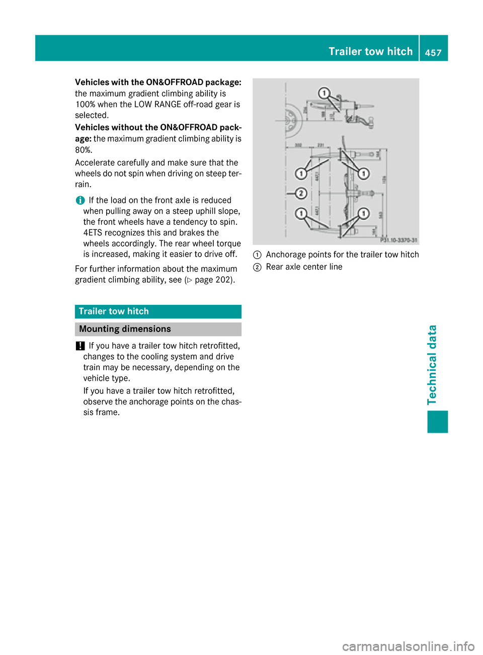
If you have a trailer tow hitch retrofitted,
observe the anchorage points on the chas-
sis frame.
:Anchorage points for the trailer tow hitch
;Rear axle center line
Trailer tow hitch457
Technical data
Z
Page 461 of 462
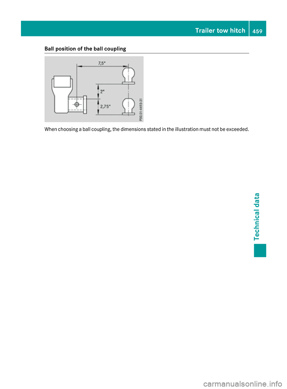
Ball position of the ball coupling
When choosing a ball coupling, the dimensions stated in the illustration must not be exceeded.
Trailer tow hitch459
Technical data
Z