trailer MERCEDES-BENZ GL SUV 2009 Owner's Manual
[x] Cancel search | Manufacturer: MERCEDES-BENZ, Model Year: 2009, Model line: GL SUV, Model: MERCEDES-BENZ GL SUV 2009Pages: 309, PDF Size: 10.27 MB
Page 198 of 309
i
The key remains inserted when you
remove the ball coupling. X
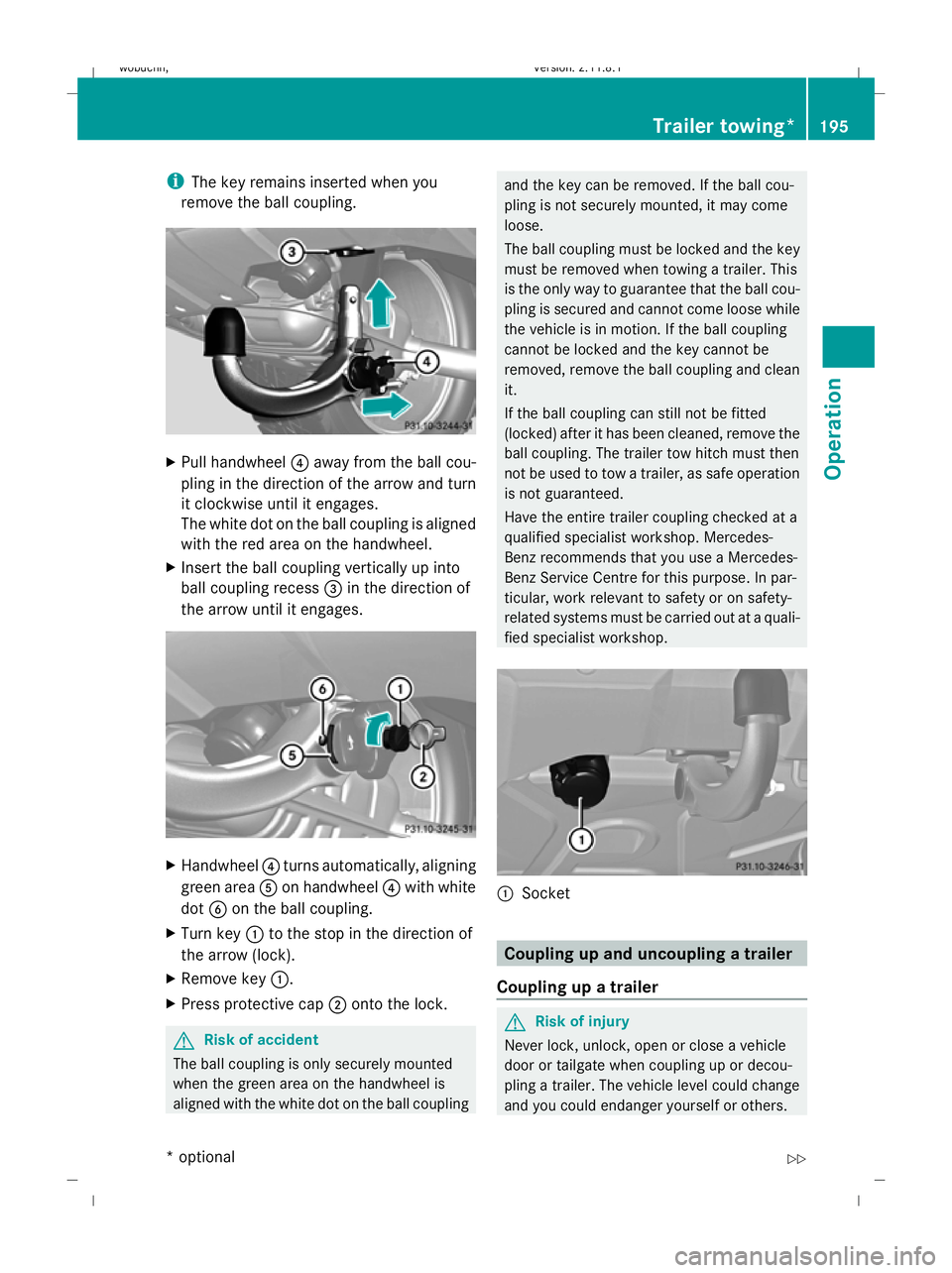
Pull handwheel ?away from the ball cou-
pling in the direction of the arrow and turn
it clockwise until it engages.
The white dot on the ball coupling is aligned
with the red area on the handwheel.
X Insert the ball coupling vertically up into
ball coupling recess =in the direction of
the arrow until it engages. X
Handwheel ?turns automatically, aligning
green area Aon handwheel ?with white
dot Bon the ball coupling.
X Turn key :to the stop in the direction of
the arrow (lock).
X Remove key :.
X Press protective cap ;onto the lock. G
Risk of accident
The ball coupling is only securely mounted
when the green area on the handwheel is
aligned with the white dot on the ball coupling and the key can be removed. If the ball cou-
pling is not securely mounted, it may come
loose.
The ball coupling must be locked and the key
must be removed when towing a trailer. This
is the only way to guarantee that the ball cou-
pling is secured and cannot come loose while
the vehicle is in motion. If the ball coupling
cannot be locked and the key cannot be
removed, remove the ball coupling and clean
it.
If the ball coupling can still not be fitted
(locked) after it has been cleaned, remove the
ball coupling. The trailer tow hitch must then
not be used to tow a trailer, as safe operation
is not guaranteed.
Have the entire trailer coupling checked at a
qualified specialist workshop. Mercedes-
Benz recommends that you use a Mercedes-
Benz Service Centre for this purpose. In par-
ticular, work relevant to safety or on safety-
related systems must be carried out at a quali-
fied specialist workshop. :
Socket Coupling up and uncoupling a trailer
Coupling up a trailer G
Risk of injury
Never lock, unlock, open or close a vehicle
door or tailgate when coupling up or decou-
pling a trailer. The vehicle level could change
and you could endanger yourself or others. Trailer towing*
195Operation
* optional
X164_AKB; 2; 3, en-GB
wobuchh,
Version: 2.11.8.1 2009-03-31T14:14:58+02:00 - Seite 195 Z
Dateiname: 6515431202_buchblock.pdf; erzeugt am 01. Apr 2009 00:17:51; WK
Page 199 of 309
Never press the ADS button* or operate the
level control* while you are coupling up or
decoupling a trailer.
X Make sure the DIRECT SELECT selector
lever is set to P.
X Depress the parking brake.
X Start the engine.
X Set the vehicle to highway level
(Y page 132).
X Set the adaptive damping system (ADS)
setting to AUTOorCOMF (Ypage 129).
X Switch off the engine.
X Close the doors and tailgate.
X Position the trailer level behind the vehicle.
X Couple up the trailer.
X Establish the electrical connection
between the vehicle and the trailer.
i If you have coupled a trailer, the vehicle
will remain at highway level.
The vehicle automatically lowers to high-
way level if you drive faster than 8 km/h
with a trailer. The vehicle is not lowered to
the high-speed level even if you are travel-
ling at higher speeds.
This also applies when using accessories
that are plugged into the socket of the
trailer coupling (e.g. a bicycle rack).
Decoupling a trailer G
Risk of injury
Do not disconnect a trailer with an engaged
overrun brake. Otherwise, your hand could
become trapped between the bumper and
drawbar.
! Do not uncouple a trailer with overrun
brake between the bumper and drawbar,
otherwise your vehicle could be damaged
by the spring action of the overrun brake. X
Make sure the DIRECT SELECT selector
lever is set to P.
X Depress the parking brake.
X Start the engine.
X Close the doors and tailgate.
X Secure the trailer against rolling away. G
Risk of injury
The vehicle is lowered as soon as you discon-
nect the trailer cable. Make sure that nobody
is in the vicinity of the wheel arch or the
underbody. You could otherwise trap yourself
or others.
As soon as you decouple the trailer, the unla-
den vehicle rises slightly. Make sure that you
or others are not injured in the process.
X Remove the trailer cable and decouple the
trailer.
X Switch off the engine. Notes on towing a trailer
G
Risk of accident
When reversing the vehicle towards the
trailer, make sure there is nobody between
the trailer and the vehicle.
Couple and uncouple the trailer carefully. If
you do not couple the trailer to the towing
vehicle correctly, the trailer could become
detached.
Make sure that the following values are not
exceeded:
R the permissible trailer drawbar noseweight
R the permissible trailer load
R the permissible rear axle load of the towing
vehicle
R the maximum permissible gross vehicle
weight of both the towing vehicle and the
trailer
You will find the applicable permissible val-
ues, which must not be exceeded, in the vehi-
cle documents. 196
Trailer towing*Operation
* optional
X164_AKB; 2; 3, en-GB
wobuchh
,V ersion: 2.11.8.1
2009-03-31T14:14:58+02:00 - Seite 196
Dateiname: 6515431202_buchblock.pdf; erzeugt am 01. Apr 2009 00:17:51; WK
Page 200 of 309
You will find the values approved by the man-
ufacturer on the vehicle identification plates
and those for the towing vehicle in the "Tech-
nical data" section.
You will find installation dimensions and loads
in the "Technical data" section
(Y page 297).
The maximum drawbar load of the trailer
drawbar on the ball coupling is 140 kg. How-
ever, the actual noseweight must not exceed
the value given on the trailer coupling or
trailer identification plates. The lowest weight
applies.
! Use a noseweight as close as possible to
the maximum permissible noseweight. Do
not use a noseweight of less than 50 kg,
otherwise the trailer may come loose.
Bear in mind that the payload and the rear
axle load are reduced by the actual nose-
weight.
When towing a trailer, where possible set the
tyre pressures for the permissible gross
weight which you find in the table on the
inside of your vehicle's fuel filler flap (higher
values).
Driving tips i
Observe the notes on ESP ®
trailer stabi-
lisation (Y page 51).
In Germany, the maximum permissible speed
for vehicle/trailer combinations depends on
the type of trailer and is either 80 km/h or
100 km/h. Before beginning the journey,
check the trailer's documents to see what the
maximum permitted speed is. G
Risk of accident
Always observe the maximum speed permit-
ted in Germany for vehicle/trailer combina-
tions, even in countries where higher speeds
are permitted. This lowers the risk of an acci-
dent. When towing a trailer, your vehicle's handling
characteristics will be different in comparison
to when driving without a trailer.
The vehicle/trailer combination:
R is heavier
R is restricted in its acceleration and gradi-
ent-climbing capability
R has an increased braking distance
R is affected more by strong crosswinds
R demands more sensitive steering
R consumes more fuel
On long and steep downhill gradients, you
must select shift range 1,2or 3in good time.
i This also applies if you have activated
cruise control, Distronic* or Speedtronic.
This will use the braking effect of the engine,
so less braking will be required to maintain
the speed. This relieves the load on the brake
system and prevents the brakes from over-
heating and wearing too quickly. If you need
additional braking, depress the brake pedal
repeatedly rather than continuously. G
Risk of accident
Never depress the brake pedal continuously
while the vehicle is in motion, e.g. never cause
the brakes to rub by applying constant slight
pedal pressure. This causes the brake system
to overheat, increases the braking distance
and can lead to the brakes failing completely.
Driving tips
R Maintain a greater distance from the vehi-
cle in front than when driving without a
trailer.
R Avoid braking abruptly. If possible, brake
gently at first to allow the trailer to run on.
Then, increase the braking force rapidly.
R The values given for gradient-climbing
capabilities from a standstill refer to sea
level. When driving in mountainous areas,
note that the power output of the engine,
and consequently the vehicle's gradient- Trailer towing*
197Operation
* optional
X164_AKB; 2; 3, en-GB
wobuchh
,V ersion: 2.11.8.1
2009-03-31T14:14:58+02:00 - Seite 197 Z
Dateiname: 6515431202_buchblock.pdf; erzeugt am 01. Apr 2009 00:17:52; WK
Page 201 of 309
climbing capability, decrease with increas-
ing altitude.
If the trailer swings from side to side:
X Do not accelerate.
X Do not counter-steer.
X Brake if necessary. G
Risk of accident
On no account should you attempt to draw the
vehicle/trailer combination out by increasing
speed. Folding in the ball coupling
i Fold the ball coupling back in if you are
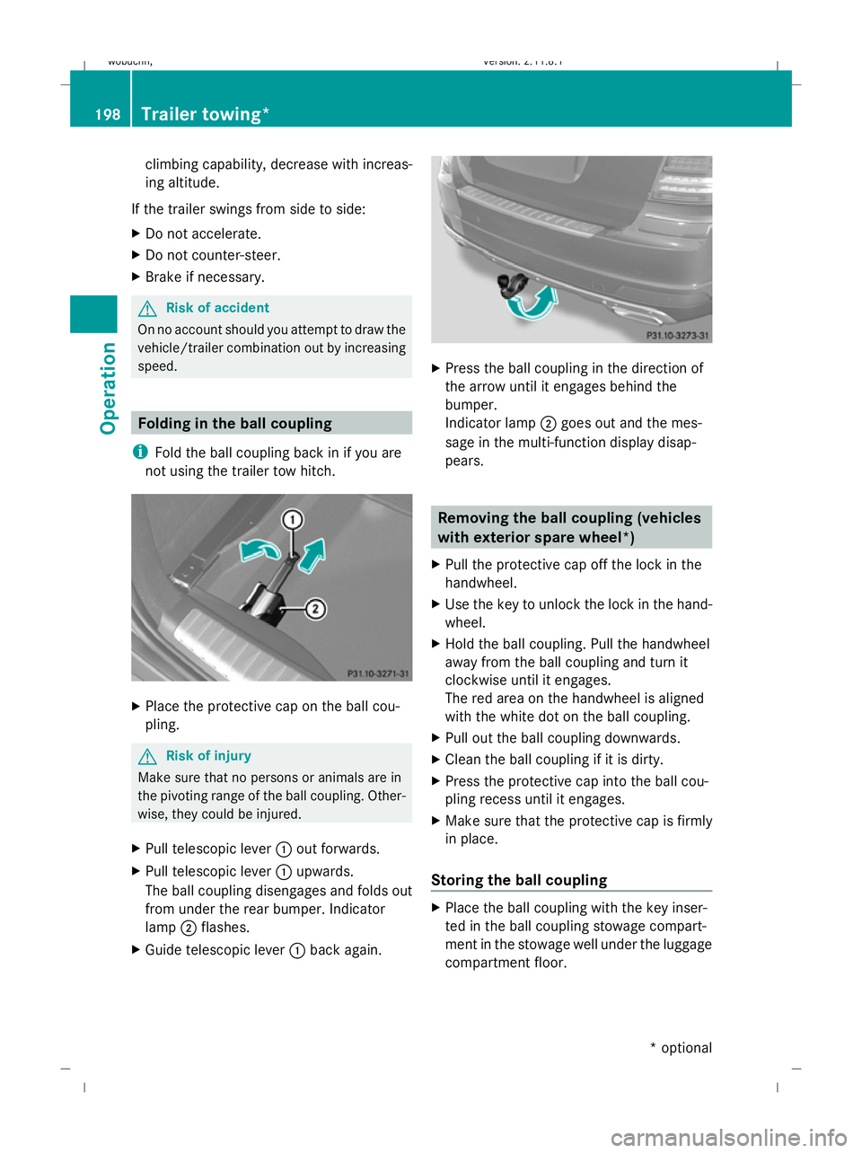
not using the trailer tow hitch. X
Place the protective cap on the ball cou-
pling. G
Risk of injury
Make sure that no persons or animals are in
the pivoting range of the ball coupling. Other-
wise, they could be injured.
X Pull telescopic lever :out forwards.
X Pull telescopic lever :upwards.
The ball coupling disengages and folds out
from under the rear bumper. Indicator
lamp ;flashes.
X Guide telescopic lever :back again. X
Press the ball coupling in the direction of
the arrow until it engages behind the
bumper.
Indicator lamp ;goes out and the mes-
sage in the multi-function display disap-
pears. Removing the ball coupling (vehicles
with exterior spare wheel*)
X Pull the protective cap off the lock in the
handwheel.
X Use the key to unlock the lock in the hand-
wheel.
X Hold the ball coupling. Pull the handwheel
away from the ball coupling and turn it
clockwise until it engages.
The red area on the handwheel is aligned
with the white dot on the ball coupling.
X Pull out the ball coupling downwards.
X Clean the ball coupling if it is dirty.
X Press the protective cap into the ball cou-
pling recess until it engages.
X Make sure that the protective cap is firmly
in place.
Storing the ball coupling X
Place the ball coupling with the key inser-
ted in the ball coupling stowage compart-
ment in the stowage well under the luggage
compartment floor. 198
Trailer towing*Operation
* optional
X164_AKB; 2; 3, en-GB
wobuchh,
Version: 2.11.8.1 2009-03-31T14:14:58+02:00 - Seite 198
Dateiname: 6515431202_buchblock.pdf; erzeugt am 01. Apr 2009 00:17:52; WK
Page 202 of 309

G
Risk of accident
Do not carry the ball coupling in the vehicle
interior if it is not secured.
Otherwise, you and others could be injured by
the ball coupling being thrown around if you:
R brake sharply
R change direction suddenly
R are involved in an accident
Information on cleaning and care of the trailer
coupling can be found at (Y page 203).Trailer power supply
When it leaves the factory, your vehicle's
trailer socket outlet is equipped with a per-
manent power supply and a power supply that
is switched on via the ignition lock.
The permanent power supply is supplied via
trailer socket pin 9.
The power supply that is switched on via the
ignition lock is supplied via trailer socket
pin 10.
! You can connect consumers with a power
rating of up to 240 W to the permanent
power supply and up to 180 W to the power
supply that is switched on via the ignition
lock.
You must not charge a trailer battery using
the power supply.
The trailer's turn signal lamps are only guar-
anteed to function when bulbs are used.
You can obtain further information about
installing the trailer electrics from a qualified
specialist workshop, e.g. a Mercedes-Benz
Service Centre.
X To switch the connected power supply
on or off: turn the key in the ignition lock
to position 2or 0, respectively. Trailer with 7-pin connector
If your trailer has a 7-pin connector, you can
connect it to the 13-pin socket on the ball
coupling using an adapter or, if necessary, an
adapter cable. Both of these can be obtained
at a qualified specialist workshop, e.g. at a
Mercedes-Benz Service Centre.
Fitting the adapter X
Open the socket cover.
X Insert connector with lug :into
groove ;on the socket and turn the con-
nector clockwise to the stop.
X Make the cover engage.
X If you are using an adapter cable, secure
the cable to the trailer with cable ties.
! Make sure that there is sufficient cable
play so that the cable cannot become
detached when cornering. Service
ASSYST PLUS service interval display
The ASSYST PLUS service interval display
informs you of the next service due date.
The service due date is shown in the multi-
function display, for example:
Service A in .. days
Service A in .. km
Service A due now
The letter indicates how much time the work-
shop will require to carry out the service work. Service
199Operation
X164_AKB; 2; 3, en-GB
wobuchh, Version: 2.11.8.1 2009-03-31T14:14:58+02:00 - Seite 199 Z
Dateiname: 6515431202_buchblock.pdf; erzeugt am 01. Apr 2009 00:17:52; WK
Page 206 of 309
!
Do not clean the wiper blades too often,
and avoid rubbing too hard, as this could
result in damage to the graphite coating.
This could cause wiper noise.
X Fold the wiper arms away from the wind-
screen.
X Clean the wiper blades carefully with a
damp cloth.
X Fold the wiper arms back again before
switching on the ignition.
Cleaning the headlamps X
Clean the plastic lenses of the headlamps
with a wet sponge and windscreen washer
fluid or cleaning cloths.
! Only use washer fluid or cleaning cloths
suitable for plastic lenses. Unsuitable
washer fluid or cleaning cloths could
scratch or damage the plastic lenses of the
headlamps.
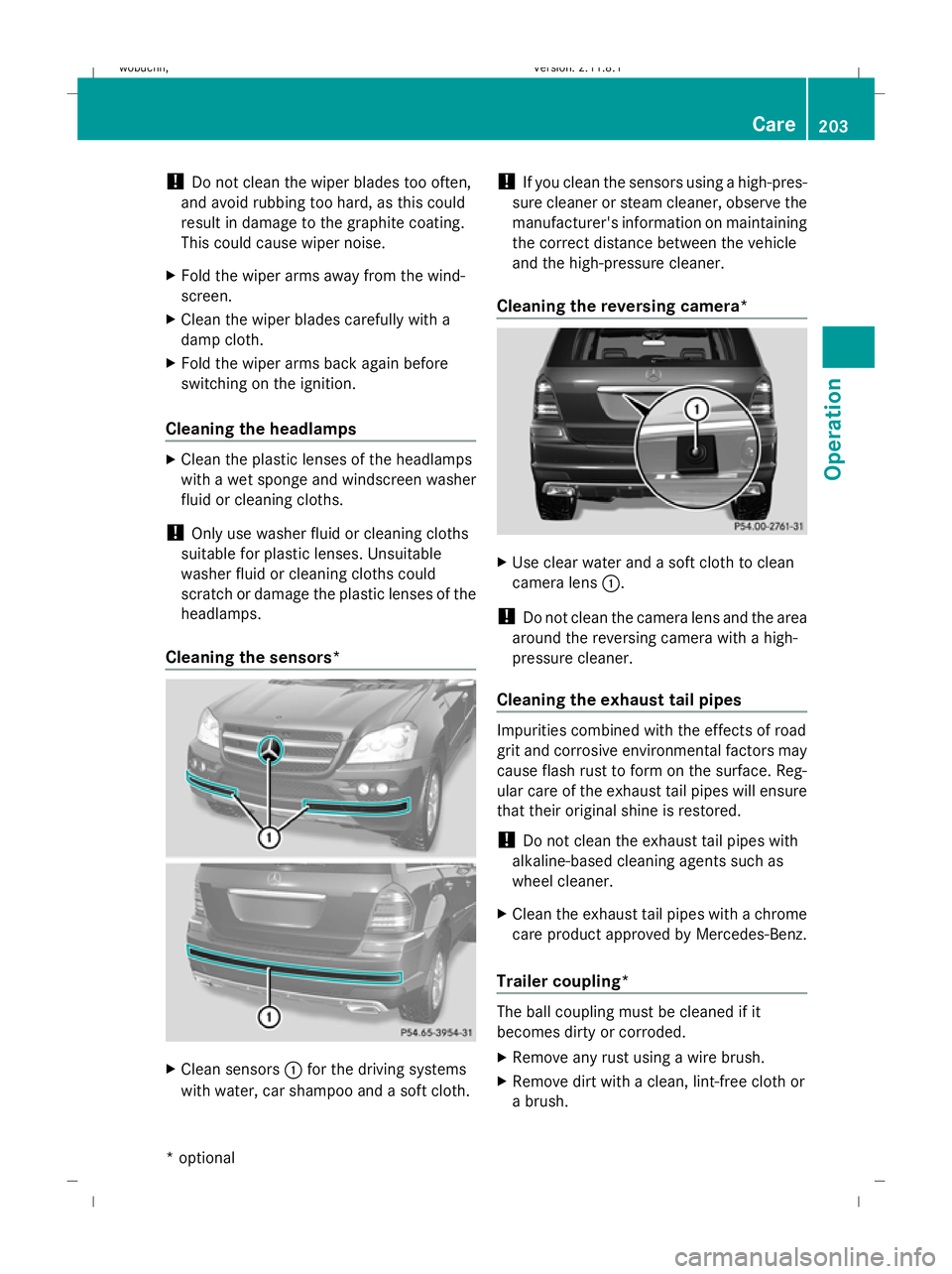
Cleaning the sensors* X
Clean sensors :for the driving systems
with water, car shampoo and a soft cloth. !
If you clean the sensors using a high-pres-
sure cleaner or steam cleaner, observe the
manufacturer's information on maintaining
the correct distance between the vehicle
and the high-pressure cleaner.
Cleaning the reversing camera* X
Use clear water and a soft cloth to clean
camera lens :.
! Do not clean the camera lens and the area
around the reversing camera with a high-
pressure cleaner.
Cleaning the exhaust tail pipes Impurities combined with the effects of road
grit and corrosive environmental factors may
cause flash rust to form on the surface. Reg-
ular care of the exhaust tail pipes will ensure
that their original shine is restored.
!
Do not clean the exhaust tail pipes with
alkaline-based cleaning agents such as
wheel cleaner.
X Clean the exhaust tail pipes with a chrome
care product approved by Mercedes-Benz.
Trailer coupling* The ball coupling must be cleaned if it
becomes dirty or corroded.
X
Remove any rust using a wire brush.
X Remove dirt with a clean, lint-free cloth or
a brush. Care
203Operation
* optional
X164_AKB; 2; 3, en-GB
wobuchh,
Version: 2.11.8.1 2009-03-31T14:14:58+02:00 - Seite 203 Z
Dateiname: 6515431202_buchblock.pdf; erzeugt am 01. Apr 2009 00:17:53; WK
Page 207 of 309
!
Do not clean the ball coupling with a high-
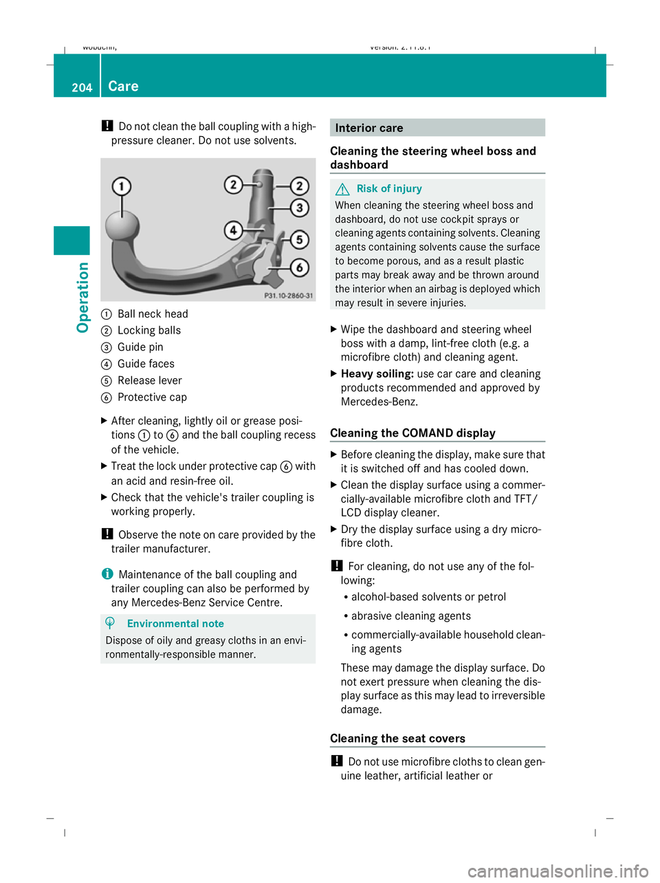
pressure cleaner. Do not use solvents. :
Ball neck head
; Locking balls
= Guide pin
? Guide faces
A Release lever
B Protective cap
X After cleaning, lightly oil or grease posi-
tions :toB and the ball coupling recess
of the vehicle.
X Treat the lock under protective cap Bwith
an acid and resin-free oil.
X Check that the vehicle's trailer coupling is
working properly.
! Observe the note on care provided by the
trailer manufacturer.
i Maintenance of the ball coupling and
trailer coupling can also be performed by
any Mercedes-Benz Service Centre. H
Environmental note
Dispose of oily and greasy cloths in an envi-
ronmentally-responsible manner. Interior care
Cleaning the steering wheel boss and
dashboard G
Risk of injury
When cleaning the steering wheel boss and
dashboard, do not use cockpit sprays or
cleaning agents containing solvents. Cleaning
agents containing solvents cause the surface
to become porous, and as a result plastic
parts may break away and be thrown around
the interior when an airbag is deployed which
may result in severe injuries.
X Wipe the dashboard and steering wheel
boss with a damp, lint-free cloth (e.g. a
microfibre cloth) and cleaning agent.
X Heavy soiling: use car care and cleaning
products recommended and approved by
Mercedes-Benz.
Cleaning the COMAND display X
Before cleaning the display, make sure that
it is switched off and has cooled down.
X Clean the display surface using a commer-
cially-available microfibre cloth and TFT/
LCD display cleaner.
X Dry the display surface using a dry micro-
fibre cloth.
! For cleaning, do not use any of the fol-
lowing:
R alcohol-based solvents or petrol
R abrasive cleaning agents
R commercially-available household clean-
ing agents
These may damage the display surface. Do
not exert pressure when cleaning the dis-
play surface as this may lead to irreversible
damage.
Cleaning the seat covers !
Do not use microfibre cloths to clean gen-
uine leather, artificial leather or 204
CareOperation
X164_AKB; 2; 3, en-GB
wobuchh,
Version: 2.11.8.1 2009-03-31T14:14:58+02:00 - Seite 204
Dateiname: 6515431202_buchblock.pdf; erzeugt am 01. Apr 2009 00:17:54; WK
Page 224 of 309
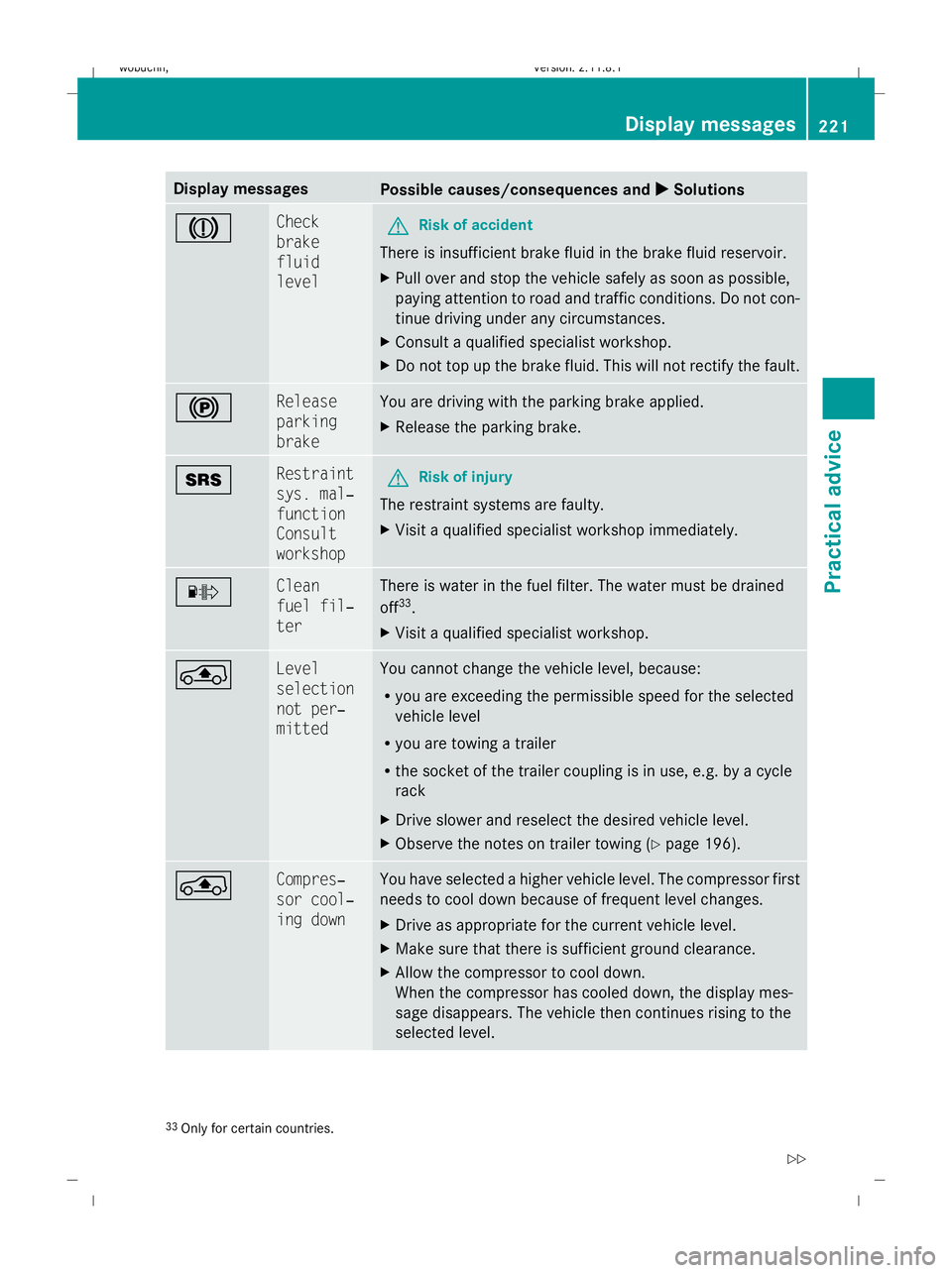
Display messages
Possible causes/consequences and
X
X Solutions J Check
brake
fluid
level
G
Risk of accident
There is insufficient brake fluid in the brake fluid reservoir.
X Pull over and stop the vehicle safely as soon as possible,
paying attention to road and traffic conditions. Do not con-
tinue driving under any circumstances.
X Consult a qualified specialist workshop.
X Do not top up the brake fluid. This will not rectify the fault. ! Release
parking
brake You are driving with the parking brake applied.
X
Release the parking brake. + Restraint
sys. mal‐
function
Consult
workshop
G
Risk of injury
The restraint systems are faulty.
X Visit a qualified specialist workshop immediately. · Clean
fuel fil‐
ter There is water in the fuel filter. The water must be drained
off
33
.
X Visit a qualified specialist workshop. ° Level
selection
not per‐
mitted You cannot change the vehicle level, because:
R
you are exceeding the permissible speed for the selected
vehicle level
R you are towing a trailer
R the socket of the trailer coupling is in use, e.g. by a cycle
rack
X Drive slower and reselect the desired vehicle level.
X Observe the notes on trailer towing (Y page 196).° Compres‐
sor cool‐
ing down You have selected a higher vehicle level. The compressor first
needs to cool down because of frequent level changes.
X
Drive as appropriate for the current vehicle level.
X Make sure that there is sufficient ground clearance.
X Allow the compressor to cool down.
When the compressor has cooled down, the display mes-
sage disappears. The vehicle then continues rising to the
selected level. 33
Only for certain countries. Display
messages
221Practical advice
X164_AKB; 2; 3, en-GB
wobuchh,V ersion: 2.11.8.1
2009-03-31T14:14:58+02:00 - Seite 221 Z
Dateiname: 6515431202_buchblock.pdf; erzeugt am 01. Apr 2009 00:17:59; WK
Page 228 of 309
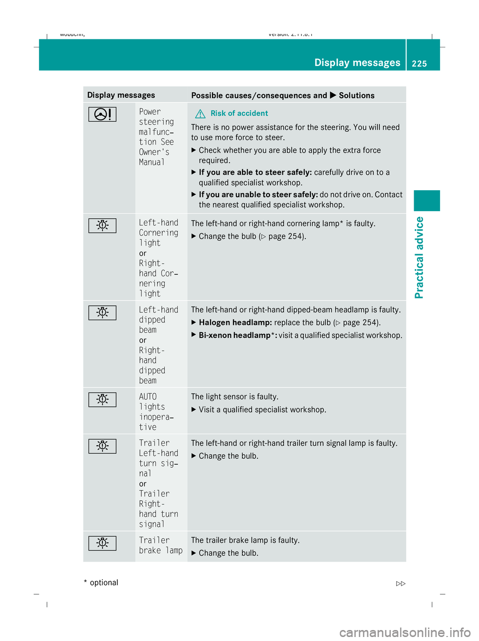
Display messages
Possible causes/consequences and
X
X Solutions D Power
steering
malfunc‐
tion See
Owner's
Manual
G
Risk of accident
There is no power assistance for the steering. You will need
to use more force to steer.
X Check whether you are able to apply the extra force
required.
X If you are able to steer safely: carefully drive on to a
qualified specialist workshop.
X If you are unable to steer safely: do not drive on. Contact
the nearest qualified specialist workshop. b Left-hand
Cornering
light
or
Right-
hand Cor‐
nering
light
The left-hand or right-hand cornering lamp* is faulty.
X
Change the bulb ( Ypage 254). b Left-hand
dipped
beam
or
Right-
hand
dipped
beam The left-hand or right-hand dipped-beam headlamp is faulty.
X
Halogen headlamp: replace the bulb (Ypage 254).
X Bi-xenon headlamp*: visit a qualified specialist workshop. b AUTO
lights
inopera‐
tive The light sensor is faulty.
X
Visit a qualified specialist workshop. b Trailer
Left-hand
turn sig‐
nal
or
Trailer
Right-
hand turn
signal The left-hand or right-hand trailer turn signal lamp is faulty.
X
Change the bulb. b Trailer
brake lamp The trailer brake lamp is faulty.
X
Change the bulb. Display
messages
225Practical advice
* optional
X164_AKB; 2; 3, en-GB
wobuchh
,V ersion: 2.11.8.1
2009-03-31T14:14:58+02:00 - Seite 225 Z
Dateiname: 6515431202_buchblock.pdf; erzeugt am 01. Apr 2009 00:18:00; WK
Page 229 of 309
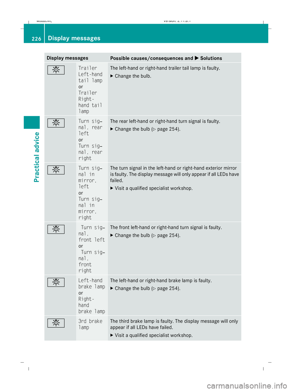
Display messages
Possible causes/consequences and
X
X Solutions b Trailer
Left-hand
tail lamp
or
Trailer
Right-
hand tail
lamp The left-hand or right-hand trailer tail lamp is faulty.
X
Change the bulb. b Turn sig‐
nal, rear
left
or
Turn sig‐
nal, rear
right The rear left-hand or right-hand turn signal is faulty.
X
Change the bulb ( Ypage 254). b Turn sig‐
nal in
mirror,
left
or
Turn sig‐
nal in
mirror,
right The turn signal in the left-hand or right-hand exterior mirror
is faulty. The display message will only appear if all LEDs have
failed.
X
Visit a qualified specialist workshop. b Turn sig‐
nal,
front left
or
Turn sig‐
nal,
front
right The front left-hand or right-hand turn signal is faulty.
X
Change the bulb ( Ypage 254). b Left-hand
brake lamp
or
Right-
hand
brake lamp The left-hand or right-hand brake lamp is faulty.
X
Change the bulb ( Ypage 254). b 3rd brake
lamp The third brake lamp is faulty. The display message will only
appear if all LEDs have failed.
X
Visit a qualified specialist workshop. 226
Display
messagesPractical advice
X164_AKB; 2; 3, en-GB
wobuchh,V ersion: 2.11.8.1
2009-03-31T14:14:58+02:00 - Seite 226
Dateiname: 6515431202_buchblock.pdf; erzeugt am 01. Apr 2009 00:18:00; WK