mirror MERCEDES-BENZ GL SUV 2012 Owner's Guide
[x] Cancel search | Manufacturer: MERCEDES-BENZ, Model Year: 2012, Model line: GL SUV, Model: MERCEDES-BENZ GL SUV 2012Pages: 441, PDF Size: 10.66 MB
Page 229 of 441
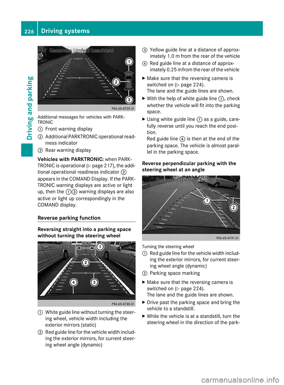
Additiona
lmessages for vehicles with PARK-
TRONIC
: Fron twarning display
; Additiona lPARKTRONIC operationa lread-
iness indicator
= Rear warning display
Veh icleswithP ARKTRONIC: when PARK-
TRONIC is operationa l(Y page 217), the addi-
tional operat iona lreadiness indicator ;
appears in the COMAN DDisplay. If the PARK-
TRONIC warnin gdisplays are active or light
up ,then the :=warnin gdisplays are also
active or light up correspondingl yinthe
COMAND display.
Reverse parkin gfunction Reversin
gstraight into aparkin gspace
withou tturning the ste eringwheel :
White gu idel ine without turning the steer-
ing wheel, vehicle width including the
exterior mirrors (static)
; Red guide line for the vehicle width includ-
ing the exterior mirrors, for current steer-
ing wheel angle (dynamic) =
Yellow guide line at adistance of approx-
imately 1.0 mfrom th erear of the vehic le
? Red guide line at adistance of approx-
imately 0.2 5mfrom th erear of the vehic le
X Ma ke sure that the reversing camera is
switched on (Y page224).
Th elane and the guide lines are sho wn.
X Wi th the hel pofwhite guide line :,check
whether the vehicle will fit into the parking
space.
X Using white guide line :asag uide, care-
fully reverse until you reach the end posi-
tion.
Red guide line ?is then at the end of the
parking space. The vehicle is almost paral-
lel in the parking space.
Reverse perpendicular parking with the
steering wheel at an angle Turning the steering wheel
:
Red guide line for the vehicle width includ-
ing the exterior mirrors, for current steer-
ing wheel angle (dynamic)
; Parking space marking
X Make sure that the reversing camera is
switched on (Y page 224).
The lane and the guide lines are shown.
X Drive past the parking space and bring the
vehicle to astandstill.
X While the vehicle is at astandstill, turn the
steering whee lint he direction of the park- 226
Driving systemsDriving and pa
rking
Page 231 of 441
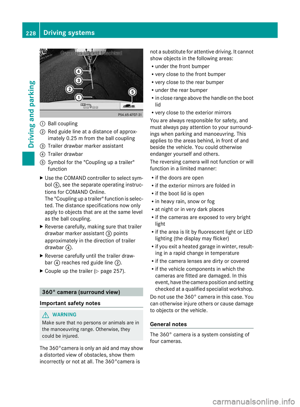
:
Ballcoupling
; Red guid elineatad istance of approx-
imately 0.25 mfromt he ball coupling
= Trailer drawbar marker assistant
? Trailer drawbar
A Symbol for the "Coupling up atrailer"
functi on
X Use th eCOM AND controlle rtoselect sym-
bol A,s ee the separate operating instruc-
tions for COMAN DOnline.
The "Coupling up atrailer" functio nisselec-
ted. The distance specification snow only
apply to objec tsthat are at the same level
as the ball coupling.
X Reverse carefully, making sure that trailer
drawbar marker assistant =points
approximately in the directio noftrailer
drawbar ?.
X Revers ecarefully until the trailer draw-
bar ?reaches red guide line ;.
X Couple up the trailer (Y page 257).360° camera (surround view)
Important safety notes G
WARNING
Make sure that no persons or animals are in
the manoeuvring range. Otherwise, they
could be injured.
The 360°camera is only an aid and may show
ad istorted view of obstacles, show them
incorrectly or not at all. The 360°camer aisnot
asubstitute for attentiv edriving. It cannot
sho wobjects in the following areas:
R under the fr ontb um per
R very clos etothe frontb um per
R very clos etothe rear bumper
R unde rthe rear bumper
R in close range abov ethe handle on th eboot
lid
R ver yclose to th eexter ior mirrors
You are always responsible for safety, and
must always pay attention to your surround-
ing sw hen par king and manoeuvring. This
applies to the areas behind ,inf ront of and
beside th evehicle. Yo ucould otherwise
endanger yoursel fand oth ers.
The rever sing camera will not functi on or will
function in alimited manner:
R if the doors are open
R if the exterior mir rors are folde din
R if the boot lid is open
R in heavy rain, snow or fog
R at night or in very dark places
R if the cameras are exposed to very bright
light
R if the area is lit by fluorescen tlight or LED
lightin g(the display may flicker)
R if you exit aheate dgarage in winter, result-
ing in arapid change in temperature
R if the camera lenses are dirt yorcovered
R if the vehicle component sinwhich the
cam erasare fitted are damaged .Inthis
event, hav ethe cam eraposition and setting
checked at aqualified specialist workshop.
Do not use the 360 °camer aint his case .You
can otherwise injur eothersorc ause damage
to object sorthe vehicle.
Ge neral notes The 360° camera is
asystem consisting of
four cameras. 228
Drivin
gsystemsDriving and parking
Page 232 of 441
The system evaluates images from the fol-
lowin gcameras:
R reversin gcamera
R fron tcamera
R two cameras in the exterior rear view mir-
rors
The cameras capture the immediate sur-
roundings of the vehicle. The system sup-
ports you, e.g. when parking or if vision is
restricted at an exit.
The 360 °camera images can be shown in full
screen mode or in seven different split-screen
views on the COMAND display. Asplit-screen
view also includes atop view of the vehicle.
This view is calculated from the data supplied
by the installed camera s(virtual camera).
Th e7s plit-screen views are:
R top view and picture from the reversing
camera (13 0°viewing angle)
R top view and picture from the fron tcamera
(without displaying the maximum steering
wheel angle)
R top view and enlarged rear view
R top view and enlarged front view
R top view and trailer view (vehicles with
trailer tow hitch)
R top view and pictures from the rearward
facin gmirror cameras (rear wheel view)
R top view and pictures from the forward
facin gmirror cameras (fron twheel view)
i The top vie wand trailer view are available
for vehicles equipped with atrailer tow
hitch.
When th efunction is active and you shift the
transmission from position Dor Rto N,y ou
see the previous view in the COMAN Ddis-
play. The dynamic guidelines are hidden.
When you change between transmission
positions Dand R,you see the previously
selected front or rea rview. Activation conditions The 360
°camera image can be displ ayed if:
R your vehicle is equip pedw ith the 360°
camera.
R COMAND Online is switched on, see the
separate COMAND Online operating
instruc tions.
R the 360° camera func
tion is activated
Activating th e360° camera using the
SYS but ton X
Press and hold the Wbutton for longer
than 2seconds, see the separate COMAND
Online operatin ginstructions.
Depe nding on whether position Dor Ris
engaged, the following is shown:
R full screen display with the image from
the fron tcamera
R full screen display with the image from
the rear camera.
Activating the 360° camer awith
COMAN DOnline X
Press the Wbutton, see the separate
COMAN DOnline operating instructi ons.
X Select System by turning
cVdthe
COMAND contr ollerand press Wto con-
firm.
X Select 360°camera and press
Wto con-
firm.
Depending on whethe rposition Dor Ris
engaged, the following is shown:
R as plit screen with top view and the
image from the front camera or
R as plit screen with top view and the
image from the reversing camera.
For further information about the COMAND
Controller, see the separat eCOMAN DOnline
operating instructions. Drivin
gsystems
229Drivingand pa rking Z
Page 233 of 441
Activating th
e360° camera using
revers egear You can show images from th
e360°c amera
automatically by engagin grevers egear.
X Mak esuret hat the key is in position 2in
th ei gnition lock.
X Mak esuret hat the Activation by R gear setting is ac
tive in COMAND Online,
se et he separa teCOMAND Onlin eoperat-
ing instructions.
X To sho wthe360° camera image: engage
revers egear.
The COMAND display show sthe ar ea
behind th evehicl einS plitS creen:
R vehicl ewithg uide lines
R top vie wofthe vehicle
Selec ting th esplit-screen and full
screen displays X
To switch between split-scree nviews:
switc htot he line with the vehi cles ymbols
by sliding ZVthe COMAND controller.
X Turn cVd the COMAND controlle rand
select one of the vehicle symbols.
X To switch to full scree nmode: select
Full scre en by tur
ning cVd the
COMAN Dcontroller and press Wto con-
firm.
Display sinthe COMAND display Important safety notes
!
Objec tsnot at ground level may appear to
be further away than they actually are, e.g.:
R the bumpe rofaparked vehicle
R the drawbar of atrailer
R theb all coupling of atrailer to whitch
R the rear section of an HGV
R as lanted post
Use the guidelines only for orientation.
Approach object snofurther than the bot-
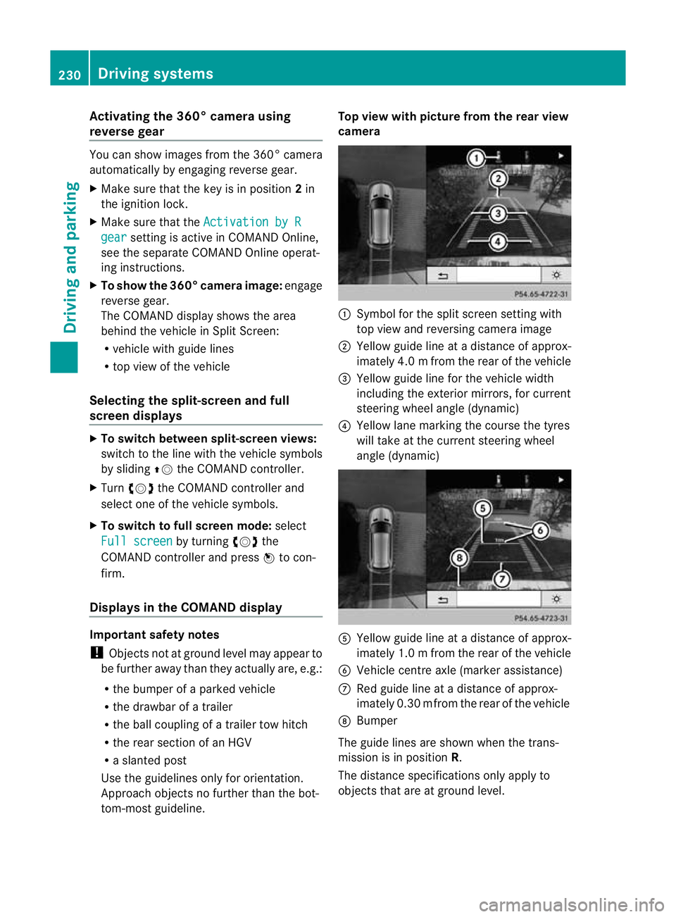
tom-most guidel ine. Top vie
wwith pictu re from the rear view
camera :
Symbol for the split screen settin gwith
top view and reversing camera image
; Yellow guide line at adistance of approx-
imately 4.0 mfrom th erear of the vehic le
= Yellow guide line for the vehicle width
including the exterior mirrors, for current
steering whee langle (dynamic)
? Yellow lane marking the course the tyres
wil ltake at the current steering wheel
angle (dynamic) A
Yellow guide line at adistance of approx-
imately 1.0 mfrom th erear of the vehic le
B Veh icle centr eaxle (marker ass istance)
C Red guide line at adistance of approx-
imately 0.3 0mfrom th erear of the vehic le
D Bumper
Th eg uide lines are sho wn whenthe trans-
mission is in position R.
The distance specifications only apply to
object sthat ar eatground level. 230
Dri
ving systemsDriving and pa rking
Page 234 of 441
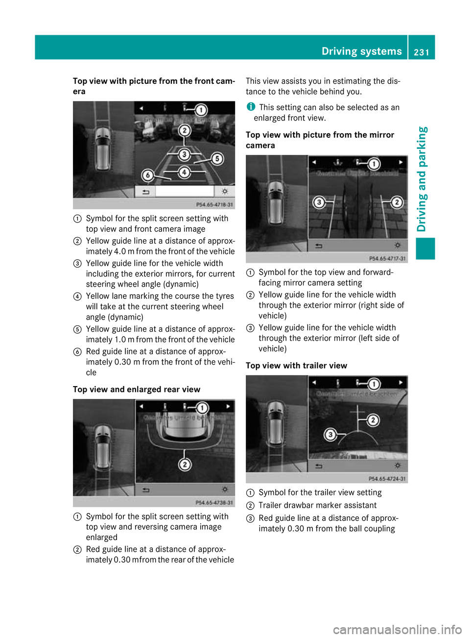
Top view with picture from the fron
tcam-
era :
Symbo lfor the split scr eens etting with
top view and front camera image
; Yellow guid elineatad istance of approx-
imatel y4.0mf rom th efront of th evehicle
= Yellow guid elinef or the vehicle width
inc ludi ng the exterio rmirrors ,for current
steering whee langle (dynamic)
? Yellow lane marking the course the tyres
will take at the current steering wheel
angle (dynamic)
A Yellow guid elineatad istance of approx-
imatel y1.0mf rom th efront of th evehicle
B Redg uide line at adistan ce of approx-
imatel y0.30 mfrom th efront of th evehi-
cle
Top view and enlarged rea rview :
Symbol for the spli tscree nsetting with
top view and reversing camera image
enlarged
; Red guide line at adistanc eofapprox-
imately 0.3 0mfrom th erear of the vehicle This view assists you in estim
ating the dis-
tance to the vehicle behind you.
i This setting can als obeselected as an
enlarged front view.
Top view with picture from th emirror
camera :
Symbo lfor the top view and forward-
facing mirror camera setting
; Yellow guide line for the vehicle width
through the exterior mirror (ri ghts ide of
vehicle)
= Yellow guide line for the vehicle width
through the exterior mirror (left side of
vehicle)
Top vie wwitht railer view :
Symbo lfor the trailer view setting
; Trailer drawbar marker assistant
= Red guide line at adistance of approx-
imately 0.3 0mfrom th eballc oupling Drivin
gsystems
231Drivingand parking Z
Page 241 of 441
Problems wit
hNight View Assist Plus Problem Possible causes/consequences and
M Solutions
The pictur
equality of
Night View Assis tPlus
has deteriorated. The windscreen wipers are smearin
gthe windscreen.
X Replace the wiper blades (Y page 132). The windscreen is smeared after the vehicle has been cleaned in
ac
ar wash.
X Clea nthe windscreen (Y page 369). There is windscreen chip damage in the camera's field of vision.
X
Replace the windscreen. The windscreen is misted up on the inside.
X
Demist the windscreen (Y page 145). The windscreen is iced up.
X
De-ice the windscreen (Y page 145). There is dir
tonthe insid eofthe windscreen.
X Clean the insid eofthe windscreen (Y page 369). Lan
eTracking package
General notes The Lane Tracking package consis
tsof Blind
Spot Assist (Y page 238) and Lane Keeping
Assist (Y page 240).
Blind Spot Assist Important safety notes
G
WARNING
Blind Spot Assist is only an aid designe dto
assis tdriving. It may fail to detec tsome vehi-
cles and is no substitute for attentive driving.
Blin dSpot Assist cannot detect road and traf-
fic conditions. It may fail to detect narrow
vehicles, such as motor cycles or bicycles ,or
only detec tthem too late.
Monitorin gmay be affected by dirty sensors,
stron gspray or poor visibility caused by snow,
rain or mist, for example. In this case, vehicles
are detected late or not at all. Alway
spay attention to traffic conditions and
your surroundings. Otherwise ,you may fai lto
recognise dangers in time ,cause an accident
and injure yourself and others. G
WARNING
Blind Spot Assis tisn ot active at speeds below
30 km/h. The indicator lamps in the exterior
mirror sare yello w.Vehicle sinthe monitoring
range ar ethen not indicated.
Always pay attention to traf ficc ondition sand
your surroundings. Otherwise, you may fail to
recognise dangers in time, cause an accident
and injure yourself and othe rs.
Ge nera lnotes
Blind Spot Assist uses aradar senso rsystem
to monitor the areas on both side sofyour
vehicle. It supports you from speeds of
30 km /h.Aw arning display in the exterior
mirror sdraws your attentio ntovehicles
detected in the monitored area .Ifyou then
switc hont he cor respondi ng turn signal to 238
Drivin
gsystemsDriving and parking
Page 242 of 441
change lane, yo
uwilla lsor eceive an optical
and audible collisio nwarning. For monitoring,
Active Blin dSpot Assist uses sensors in the
rear bumper.
For Blin dSpot Assist to assist you when driv-
ing, the rada rsensor system must be activa-
ted (Y page 283) and operational.
The rada rsensor system is switched off auto-
maticall yinthe vicinit yofradio telescope
facilities (Y page 433).
Monitoring range of the sensors G
WARNING
Blind Spot Assist monitors certain areas in the
immediate vicinit yofyour vehicle. Vehicles
that approach and driv epast at high speeds
are not detected. There is no display and no
warning.
If the lanes are very wide, it may not be pos-
sible to monitor the complete width of the
neighbouring lane. For this reason, vehicles in
the next lane may not be detected, especially
if they are driving in astaggered formation in
different lanes .This ma ybethe case if vehi-
cles ar edriving at th eedge of their lane that
is furthest away from your vehicle.
Alway spay attention to traffic conditions and
your surroundings. Otherwise ,you may fai lto
recognis edangers in time, cause an accident
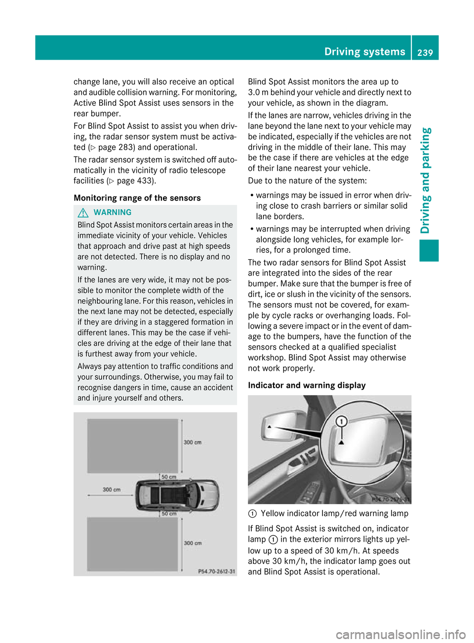
and injure yourself and others. Blind Spot Assis
tmonitors the area up to
3. 0mb ehind your vehicle and direc tlyn extto
your vehicle, as shown in the diagram.
If the lanes are narrow, vehicles drivin gint he
lan ebeyond th elan en ext to your vehicle may
be indicated, especially if th evehicles are not
drivin gint he midd le of their lane. This may
be th ecase if there are vehicles at th eedge
of their lan eneares tyour vehicle.
Due to th enature of th esystem:
R warnings may be issued in error when driv-
ing close to crash barriers or similar solid
lane borders.
R warnings may be interrupted when driving
alongside long vehicles, for example lor-
ries, for aprolonged time.
Th et wo radar sensors for Blin dSpot Assist
are integrated int othe sides of the rear
bumper .Make sure that the bumper is free of
dirt, ice or slush in the vicinity of the sensors.
The sensor smust not be covered, for exam-
ple by cycle racks or overhanging loads .Fol-
lowin gasevereimpact or in th eevent of dam-
ag etot he bumpers, hav ethe function of the
sensor schecked at aqualified special ist
workshop. Blind Spot Assist may otherwise
not work properly.
Indicator and warning display :
Yello windicato rlamp/red warning lamp
If Blind Spot Assis tiss witched on, indicator
lamp :in the exterior mirrors lights up yel-
low up to aspeed of 30 km/h. At speeds
above 30 km/h, the indicator lamp goes out
and Blin dSpot Assist is operational. Driving systems
239Driving and parking Z
Page 243 of 441
If
av ehicle is detected within the monitoring
range of Blin dSpot Assist at speed sabove
30 km/h, warning lamp :on the corre-
sponding side lights up red. This warning
alway soccurs whe navehicle enter sthe blind
spot monitoring range from behind or from
the side. When you overtak eavehicle, the
warning only occurs if the difference in speed
is less than 12 km/h.
The yellow indicator lam pgoes out if reverse
gear is engaged. Blin dSpot Assist is then
deactivated.
The brightness of the indicator/warning
lamps is adjusted autom atically according to
the ambient light.
Collision warning
If av ehicle is detected in the monitoring range
of Blin dSpot Assist and you switch on the
correspondin gturn signal ,adouble warning
tone sounds. Red warnin glamp :flashes. If
the turn signal remains on, detected vehicles
are indicated by the flashing of red warning
lamp :.There ar enofurther warning tones.
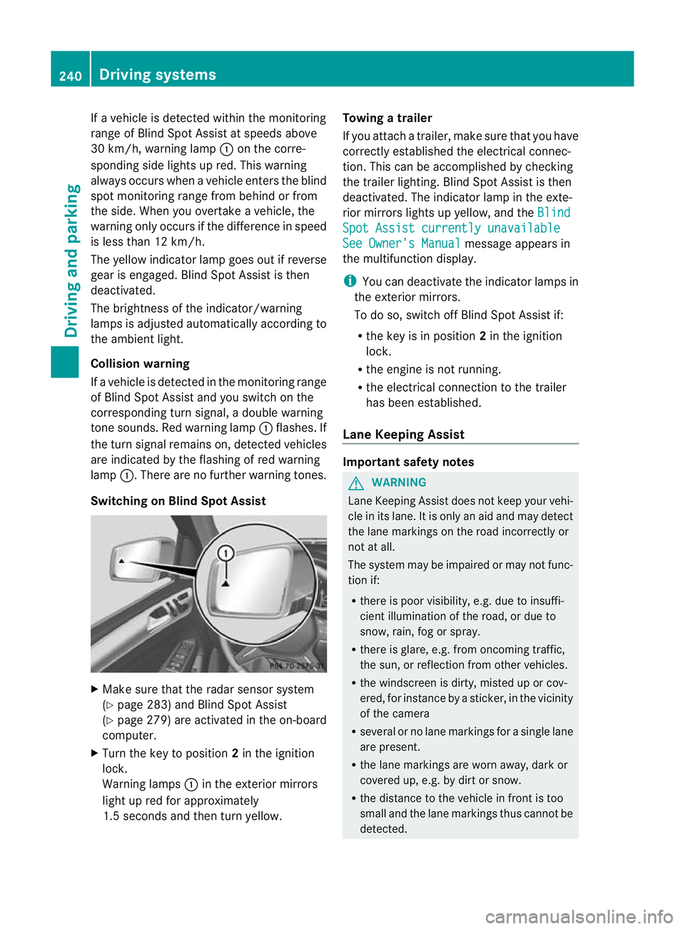
Switching on Blind Spot Assist X
Make sure that the radar senso rsystem
(Y page 283) and Blind Spot Assist
(Y page 279) are activated in the on-board
computer.
X Turn the key to position 2in the ignition
lock.
Warning lamps :in the exterior mirrors
ligh tupr ed for approximately
1. 5s econds and then tur nyellow. Towing
atrailer
If yo uattach atrailer, make sure th at you have
corre ctly established the electrical connec-
tion. This can be accomplished by checking
the trailer lighting. Blind Spot Assist is then
deactivated. The indicator lamp in the exte-
rior mirrors lights up yellow ,and the Blind Spo
tAssist currently unavailable See Owner's Manual message appears in
th em ultifunction display.
i You can deactivate the indicator lamps in
the exterior mirrors.
To do so, switch off Blind Spot Assis tif:
R thek ey is in position 2in the ignition
lock.
R the engine is not running.
R the electrical connection to the trailer
has been established.
Lane Keeping Assist Important safety notes
G
WARNING
Lan eKeeping Assist does not keep your vehi-
cle in its lane. It is only an aid and may detect
the lane markings on the road incor rectly or
not at all.
Th es ystem may be impaired or may not func-
tion if:
R there is poo rvisibility, e.g. due to insuffi-
cient illumination of the road, or due to
snow, rain, fog or spray.
R there is glare, e.g. from oncoming traffic,
the sun, or reflec tion from other vehicles.
R the windscreen is dirty, misted up or cov-
ered, for insta ncebyasticker, in the vicinity
of the camera
R several or no lane markings for asingle lane
are present.
R the lane markings are worn away, dark or
covered up, e.g. by dirt or snow.
R the distance to the vehicle in fron tist oo
smal land the lane markings thus cannot be
detected. 240
Drivin
gsystemsDrivin gand pa rking
Page 245 of 441
marking
,the system recognises certai ncon-
ditions and warns you accordingly.
The warning vibration occur searlier if:
R you approach the outer lane markin gona
bend.
R the road has ver ywidel anes ,e.g. am otor-
way.
R the system recognises solid lane markings.
The warning vibration occur slater if:
R the road has narrow lanes.
R you cut the corner on abend. Active Driving Assistance package
General notes The Active Drivin
gAssistanc epackag econ-
sists of DISTRONIC PLU S(Ypa ge198), Active
Blind Spo tAssist (Y page 242) and Active
Lane Keeping Assist (Y page 246).
Active Blind Spot Assist Importan
tsafety notes G
WARNING
Active Blind Spo tAssist is only an aid and may
detect vehicles/obstacles incorrectly or not
at all.
The system ma ybeimpaired or may not func-
tio nif:
R there is po orvisibility ,e.g. due to snow,
rain, fog or spray.
R the rear and/or front sensors are dirty.
Active Blind Spot Assist may not detect nar-
row vehi cles, such as motorcycles or bicycles,
or only detect the mtoo late. It can notd etect
vehicles which are overtaken at asmall dis-
tance and then enter th eblind spot area.
Active Blind Spot Assist cannot detect road
and traffic conditions. It is not asubstitute for
attentive driving. You are responsible for the
vehicle's speed, braking in good time, and
steering correctly. Always adapt your driving
style to suit the prevailing road and weather conditions. Always pay attention to traffic
conditions and your surroundings. Otherwise,
you may fail to recognise dangers in time,
cause an accident and injure yourself and oth-
ers.
The radar sensor syste misautomatically
deactivated near radio telescope facilities
(Y page 433).
For Active Blind Spot Assis ttoassist you
when driving, the radar sensor syste mmust
be activated (Y page 283)and operational.
General notes
Active Blind Spot Assist use saradar sensor
system to monitor the area to the sides of
your vehicle which are behind the driver. A
warning display in the exterior mirrors draws
your attention to vehicles detected in the
monitored area. If you then switch on the cor-
responding turn signal to change lane, you
will also receive an optical and audible warn-
ing. If arisk of lateral collision is detected,
corrective brakin gmay help you avoid acol-
lision. To suppor tthe course- correcting brake
application ,Active Blind Spo tAssist uses the
forward-facin gradar senso rsystem. The free
space in the direction of travel is then evalu-
ated.
Active Blind Spot Assist supports you from a
speed of approximatel y30km/h.
Monitorin grange G
WARNING
Active Blin dSpot Assist monitors cer tain
areas in the immediate vicinit yofyour vehicle.
Vehicles that approach and driv epast at high
speeds are not detected. No visual nor audi-
ble warnings are emitted and the system does
not brake the vehicle to correc tyour course.
If the lanes are ver ywide, it may not be pos-
sible to monitor the complete width of the
neighbouring lane. For this reason, vehicles in
the next lane may not be detected, especially
if they are drivin ginastaggered formation.
Thi sm ay be the case if vehicles are driving at 242
Driving systemsDrivin
gand pa rking
Page 246 of 441
the edge of their lane tha
tisfurthest away
from your vehicle.
Always pay attention to traffic conditions and
your surroundings. Otherwise, you may fail to
recognise dangers in time, cause an accident
and injure yoursel fand others. Active Blind Spo
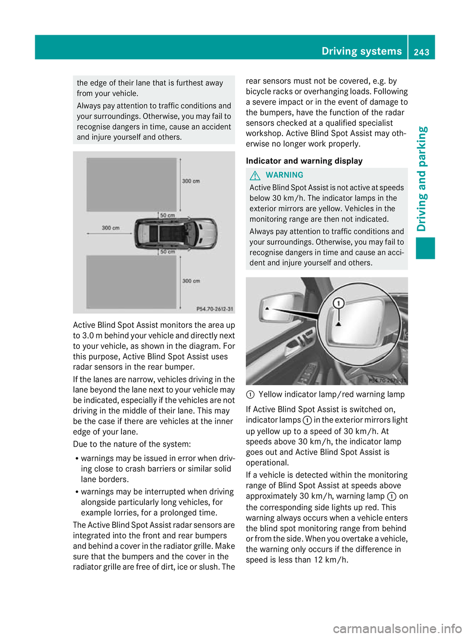
tAssist monitor sthe area up
to 3. 0mbehind your vehicle and directly next
to your vehicle, as shown in the diagram. For
this purpose, Active Blin dSpot Assist uses
rada rsensors in the rear bumper.
If the lanes are narrow, vehicles driving in the
lane beyond the lane next to your vehicle may
be indicated, especially if the vehicles are not
driving in the middle of their lane. This may
be the case if there are vehicles at the inner
edge of your lane.
Due to the nature of the system:
R warnings may be issued in error when driv-
ing close to crash barriers or similar solid
lane borders.
R warnings may be inter rupted when driving
alongside particularly long vehicles, for
example lorries, for aprolonged time.
Th eA ctive Blind Spo tAssist radar sensor sare
integ rated into the front and rear bumpers
and behind acover in the radiator grille. Make
sure that the bumpers and the cover in the
radiator grille ar efree of dirt, ice or slush. The rea
rsensors must not be covered, e.g. by
bicycle racks or overhanging loads. Following
as ever eimpact or in th eevent of damag eto
the bumpers, have the function of the radar
sensors checked at aqualified specialist
workshop. Active Blind Spot Assis tmay oth-
erwise no longer work properly.
Indicator and warning display G
WARNING
Active Blind Spot Assist is not active at speeds
below 30 km/h. The indicator lamps in the
exterior mirrors are yellow .Vehicles in the
moni toring range are then not indicated.
Always pay attention to traffic conditions and
your surroundings. Otherwise, you may fail to
recognise dangers in time and cause an acci-
dent and injure yourself and othe rs. :
Yellow indicator lamp/red warning lamp
If Active Blind Spot Assist is switched on,
indicator lamps :in the exterior mirror slight
up yellow up to aspeed of 30 km/h. At
speeds above 30 km/h, the indicator lamp
goes out and Activ eBlind Spot Assist is
operational.
If av ehicle is detected within the monitoring
range of Blin dSpot Assist at speeds above
approximately 30 km/ h,warning lamp :on
the corresponding side lights up red. This
warning always occurs when avehicle enters
th eb linds pot monitorin grange fro mbehind
or from the side. When you over take avehicle,
the warning only occu rsif the difference in
speed is less than 12 km/h. Drivin
gsystems
243Drivingand parking Z