MERCEDES-BENZ GLB SUV 2019 Owners Manual
Manufacturer: MERCEDES-BENZ, Model Year: 2019, Model line: GLB SUV, Model: MERCEDES-BENZ GLB SUV 2019Pages: 689, PDF Size: 11.39 MB
Page 151 of 689
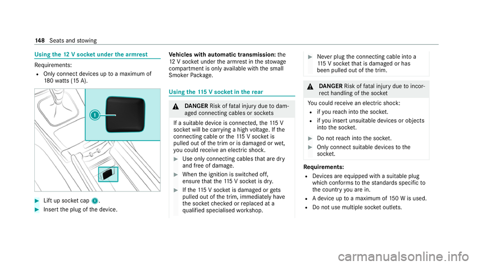
Using
the12 V so cket under the armrest Re
quirements:
R Only connect devices up toa maximum of
18 0wa tts (15 A). #
Lift up soc ket cap 1. #
Inse rtthe plug of the device. Ve
hicles with automatic transmission: the
12 V soc ket under the armrest in thestow age
compartment is on lyavailable with the small
Smoker Package. Using
the11 5 V soc ket in the rear &
DANG ER Risk of fata l injury due todam‐
aged connecting cables or soc kets
If a suitable device is connected, the11 5 V
soc ket will be car rying a high voltage. If the
connecting cable or the11 5 V soc ket is
pulled out of the trim or is damaged or wet,
yo u could recei vean electric shoc k. #
Use only connecting cables that are dry
and free of damage. #
When the ignition is switched off,
ensure that the11 5 V soc ket is dr y. #
Ifth e11 5 V soc ket is dama ged or gets
pulled out of the trim, immediately ha ve
th e soc ketch ecked or replaced at a
qu alified specialised workshop. #
Never plug the connecting cable into a
11 5 V soc ketth at is damaged or has
been pulled out of the trim. &
DANG ER Risk of fata l injury due toincor‐
re ct handling of the soc ket
Yo u could recei vean electric shock:
R ifyo ure ach into the soc ket.
R ifyo u insert unsuitable devices or objects
into the soc ket. #
Do not reach into the soc ket. #
Only connect suitable devices tothe
soc ket. Re
quirements:
R Devices are equipped with a suitable plug
which con form sto thest andards specific to
th e count ryyou are in.
R A device up toa maximum of 150 W is used.
R Do not use multiple soc ket outlets. 14 8
Seats and stowing
Page 152 of 689
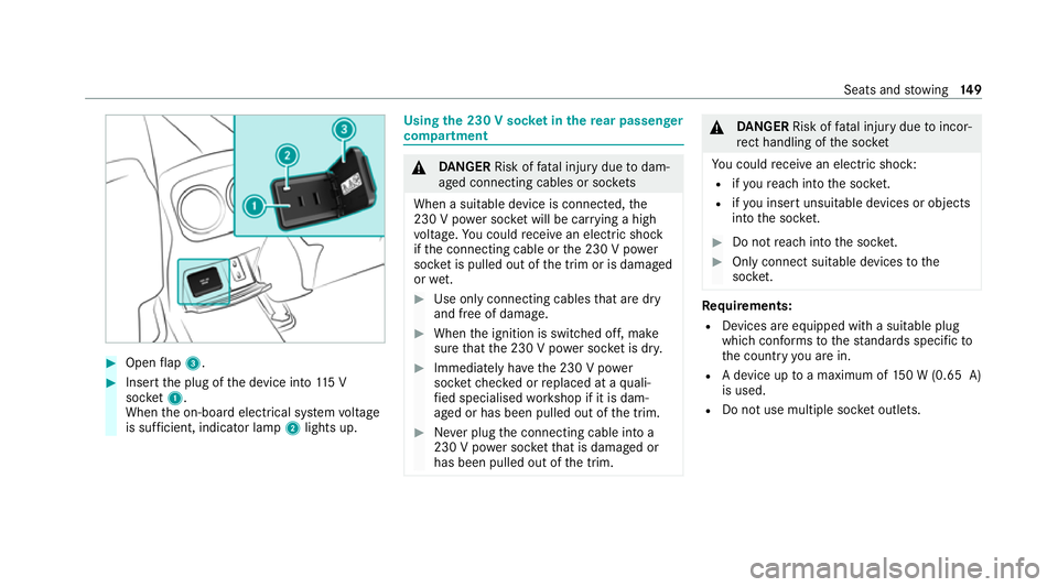
#
Open flap 3. #
Insert the plug of the device into 115 V
soc ket1.
When the on-board electrical sy stem voltage
is suf ficient, indicator la mp2lights up. Using
the 230 V soc ket in the rear passenger
comp artment &
DANG ER Risk of fata l injury due todam‐
aged connecting cables or soc kets
When a suitable device is connected, the
230 V power soc ket will be car rying a high
vo ltage. You could recei vean electric shock
if th e connecting cable or the 230 V po wer
soc ket is pulled out of the trim or is damaged
or we t. #
Use only connecting cables that are dry
and free of damage. #
When the ignition is switched off, make
sure that the 230 V po wer soc ket is dr y. #
Immedia tely ha ve the 230 V po wer
soc ketch ecked or replaced at a quali‐
fi ed specialised workshop if it is dam‐
aged or has been pulled out of the trim. #
Never plug the connecting cable into a
230 V po wer soc ketth at is damaged or
has been pulled out of the trim. &
DANG ER Risk of fata l injury due toincor‐
re ct handling of the soc ket
Yo u could recei vean electric shock:
R ifyo ure ach into the soc ket.
R ifyo u insert unsuitable devices or objects
into the soc ket. #
Do not reach into the soc ket. #
Only connect suitable devices tothe
soc ket. Re
quirements:
R Devices are equipped with a suitable plug
which con form sto thest andards specific to
th e count ryyou are in.
R A device up toa maximum of 150 W (0.65 A)
is used.
R Do not use multiple soc ket outlets. Seats and
stowing 14 9
Page 153 of 689
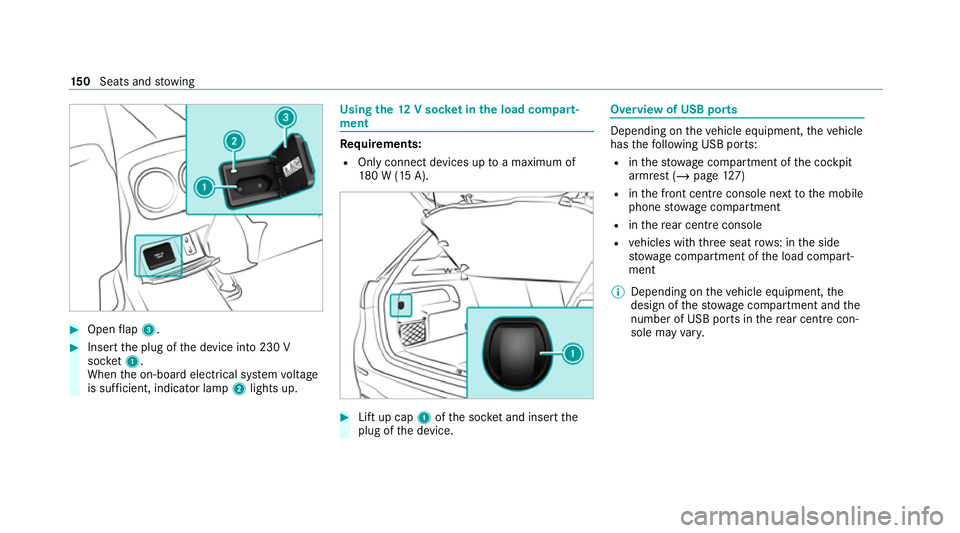
#
Open flap 3. #
Insert the plug of the device into 230 V
soc ket1.
When the on-board electrical sy stem voltage
is suf ficient, indicator la mp2lights up. Using
the12 V so cket inthe load compa rt‐
ment Re
quirements:
R Only connect devices up toa maximum of
18 0 W (15 A). #
Lift up cap 1ofthe soc ket and insert the
plug of the device. Overview of USB ports
Depending on
theve hicle equipment, theve hicle
has thefo llowing USB ports:
R inthestow age compartment of the cockpit
armrest (/ page127)
R inthe front cent reconsole next tothe mobile
phone stowage compartment
R inthere ar centre console
R vehicles with thre e seat rows: in the side
stow age compartment of the load compart‐
ment
% Depending on theve hicle equipment, the
design of thestow age compartment and the
number of USB po rts in there ar centre con‐
sole may vary. 15 0
Seats and stowing
Page 154 of 689
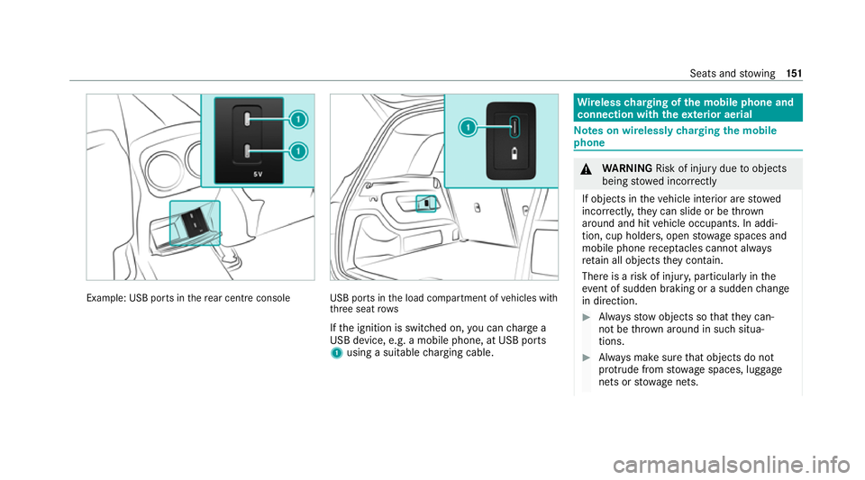
Example: USB po
rts in there ar centre console USB ports in
the load compartment of vehicles with
th re e seat rows
If th e ignition is switched on, you can charge a
USB device, e.g. a mobile phone, at USB ports
1 using a suitable charging cable. Wire
lesscharging of the mobile phone and
connection with theex terior aerial Note
s on wirelessly charging the mobile
phone &
WARNING Risk of inju rydue toobjects
being stowed inco rrectly
If objects in theve hicle interior are stowed
incor rectly, they can slide or be thrown
around and hit vehicle occupants. In addi‐
tion, cup holders, open stowage spaces and
mobile phone recep tacles cannot al ways
re tain all objects they contain.
The reis a risk of injur y,particularly in the
ev ent of sudden braking or a sudden change
in direction. #
Alw aysstow objects so that they can‐
not be throw n around in su chsitua‐
tions. #
Alw ays make sure that objects do not
pr otru de from stowage spaces, luggage
nets or stowage nets. Seats and
stowing 151
Page 155 of 689
#
Close the loc kable stow age spaces
before starting a journe y. #
Alw aysstow and secure heavy, hard,
poin ted, sharp-edged, fragile or bulky
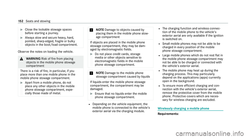
objects in the boot/load compartment. Obser
vethe no tes on loading theve hicle. &
WARNING Risk offire from placing
objects in the mobile phone stowage
compartment
There is a risk of fire , in particular, if you
place more than one mobile phone in the
mobile phone stowage compartment. #
Apart from a mobile phone, do not
place any other objects in the mobile
phone stowage compartment, espe‐
cially those made of me tal. *
NO
TEDama getoobjects caused by
placing them in the mobile phone stow‐
age compartment If objects are placed in
the mobile phone
stow age compartment, they may be dam‐
aged byelectromagnetic fields. #
Do not place credit cards, storage
media or other objects sensitive to
electromagnetic fields in the mobile
phone stowage compartment. *
NO
TEDama getothe mobile phone
stow age compartment caused byliquids If liquids enter
the mobile phone stowage
compartment, the compartment may be
damaged. #
Ensure that no liquids enter the mobile
phone stowage compartment. R
Depending on theve hicle equipment, the
mobile phone is connected totheve hicle's
ex terior aerial via thech arging module. R
The charging function and wireless connec‐
tion of the mobile phone totheve hicle's
ex terior aerial are only available if the ignition
is switched on.
R Small mobile phones may not be able tobe
ch arge d in everyposition of the mobile
phone stowage compartment.
R Largemobile phones which do not rest flat in
th e mobile phone stowage compartment may
not be able tobe charge d or connec ted with
th eve hicle's exterior aerial.
R The mobile phone may heat up during the
ch arging process. This may particular ly
depend on the applications (apps) cur rently
open in the bac kground.
R Toensure more ef ficient charging and con‐
nection with theve hicle's exterior aerial,
re mo vethe pr otective co ver from the mobile
phone. Pr otective co vers which are neces‐
sary for wireless charging are excluded. Wi
relessly charging a mobile phone Requ
irements: 15 2
Seats and stowing
Page 156 of 689
R
The mobile phone is suitable for wireless
ch arging. You can find a li stof compatible
mobile phones at:
https://www.mercedes-benz-mobile.com #
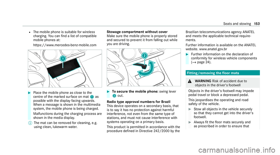
Place the mobile phone as close tothe
centre of the mar ked sur face on mat 1as
possible wi th the display facing up wards.
When a message is shown in the multimedia
sy stem, the mobile phone is being charge d.
Malfunctions during thech arging process are
shown in the media displa y.
% The mat can be remo vedfo r cleaning, e.g.
using clean, luk ewarmwate r. St
ow age comp artment with out cover
Make sure the mobile phone is proper lystored
and secured topreve nt it from falling out while
yo u are driving. #
Tosecure the mobile phone: swing lever
2 out.
Ra dio type appr oval numbers for Brazil
This device operates on a secondary basis, that
is to say it has no pr otection against harmful
inter fere nce, not even from the same type of
st ations, and must not cause inter fere nce wi th
sy stems operating on a primary basis.
This product is permitted in accordance with the
procedure defined in Directive 242/2000 bythe Brazilian
telecommunications agency AN ATEL
and meets the applicable tech nical requ ire‐
ments.
Fu rther information is available on the AN ATEL
we bsite. www.anatel.go v.br #
Further information on the declaration of
confo rmity for wireless vehicle components
(/ page 24). Fi
tting/ removing the floormats &
WARNING Risk of accident due to
objects in the driver's foot we ll
Objects in the driver's foot we ll may impede
pedal tr avel or block a depressed pedal.
This jeopardises the operating and road
saf ety of theve hicle. #
Stow all objects in theve hicle securely
so that they cannot getinto the driver's
fo ot we ll. #
Alw aysfit th efloor mats securely and
as prescribed in order toensure that Seats and
stowing 15 3
Page 157 of 689
th
ere is alw ays suf ficient room forthe
pedals. #
Do not use loose floor mats and do not
place floor mats on top of one ano ther. #
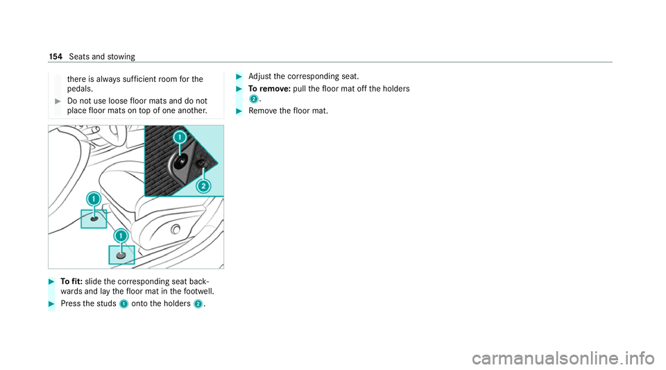
Tofit: slide the cor responding seat back‐
wa rds and lay thefloor mat in thefo ot we ll. #
Press thest uds 1onto the holders 2. #
Adjust the cor responding seat. #
Toremo ve: pull thefloor mat off the holders
2. #
Remo vethefloor mat. 15 4
Seats and stowing
Page 158 of 689
Exterior lighting
Note
s on adjusting the lights when driving
abroad It is not necessary
toadjust the headlamps. The
legal requirements are also met in countries in
which traf fic drives on theot her side of thero ad. Information about lighting sy
stems and your
re sponsibility The
various lighting sy stems of theve hicle are
only aids. The driver of theve hicle is responsible
fo r cor rect vehicle illumination in accordance
with the pr evailing light and visibility conditions,
legal requirements and traf fic situation. Light switch
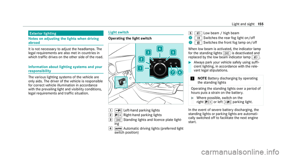
Ope
rating the light switch 1
W Left-hand pa rking lights
2 X Right-hand parking lights
3 T Standing lights and licence plate light‐
ing
4 Ã Automatic driving lights (prefer red light
switch position) 5
L Low beam / high beam
6 R Switches there ar fog light on/off
7 N Switches the front fog lamp on/off
When low beam is activated, the indicator lamp
fo rth est anding lights Tis deactivated and
re placed bythe low beam indicator lamp L. #
Alw ays park your vehicle safely using suf fi‐
cient lighting, in acco rdance with there le‐
va nt le galst ipulations.
* NO
TEBattery discharging byoperating
th est anding lights Operating
thest anding lights over a period of
hours puts a stra in on the batter y. #
Where possible, switch on the
ri ght X or left Wparking light. In
theeve nt of se vere battery discharging, the
st anding lights or parking lights are automati‐
cally swit ched off tofacilitate the next engine
st art. Light and sight
15 5
Page 159 of 689
The
exterior lighting (e xcept standing and park‐
ing lights) will swit choff automatically when the
driver's door is opened.
R Obser vethe no tes on sur round lighting
(/ page 163).
Au tomatic driving lights function
The standing lights, low beam and daytime run‐
ning lights will be switched on au tomatically
depending on the ignition status and the light
conditions. &
WARNING Risk of accident when the
dipped beam is switched off in poor visi‐
bility
When the light switch is set toà ,the
dipped beam may not be switched on auto‐
matically if there is fog, snow or other causes
of poor visibility such as spr ay.#
In such cases, turn the light switch to
L . The automatic driving lights are only an aid.
Yo u
are responsible forve hicle lighting. Switching
there ar fog lights on or off
Re quirements:
R The light switch is in theL orà posi‐
tion. #
Press the R button.
Please obser vethe count ry-specific la wsonthe
use of rear fog lamps.
Ad justing the headlamp range (halogen
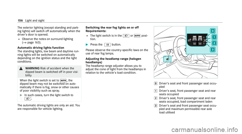
headla mps)
The headlamp range adjus ter allows youto
adjust the cone of light from the headlamps in
re lation totheve hicle's load condition. g
Driver's seat and front passenger seat occu‐
pied
1 Driver's seat, front passenger seat and rear
seats occupied
2 Driver's seat, front passenger seat and rear
seats occupied, load compartment laden
3 Driver's seat and front passenger seat occu‐
pied and maximum permissible rear axle
load utilised 15 6
Light and sight
Page 160 of 689
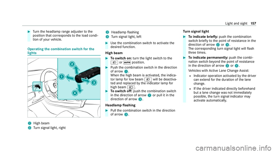
#
Turn the headlamp range adjus terto the
position that cor responds tothe load condi‐
tion of your vehicle. Operating
the combination switch for the
lights 1
High beam
2 Turn signal light, right 3
Headlamp flashing
4 Turn signal light, left #
Use the combination switch toactivate the
desired function.
High beam #
Toswitch on: turnthe light switch tothe
L orà position. #
Push the combination switch in the direction
of ar row1.
When the high beam is activated, the indica‐
to r lamp for low beam Lwill be deactiva‐
te d and replaced bythe indicator lamp for
high beam K. #
Toswitch off: pushthe combination switch
in the direction of ar row1or pull it in the
direction of ar row3.
Headlamp flashing #
Pull the combination switch in the direction
of ar row3. Tu
rn signal light #
Toindicate briefl y:push the combination
switch briefly tothe point of resis tance in the
direction of ar row2or4.
The cor responding turn signal light will flash
th re e times. #
Toindicate permanentl y:push the combi‐
nation switch be yond the point of resis tance
in the direction of ar row2or4.
Ve hicles with Active Lane Change Assi st:
R Indicator operation activated bythe driver
can extend forth e duration of the lane
ch ange.
R Ifth e driver indicated directly beforehand
but a lane change was not immediately
possible, the turn signal indicator may
activate automaticall y. Light and sight
157