technical data MERCEDES-BENZ GLC 2019 Owners Manual
[x] Cancel search | Manufacturer: MERCEDES-BENZ, Model Year: 2019, Model line: GLC, Model: MERCEDES-BENZ GLC 2019Pages: 370, PDF Size: 19.55 MB
Page 5 of 370
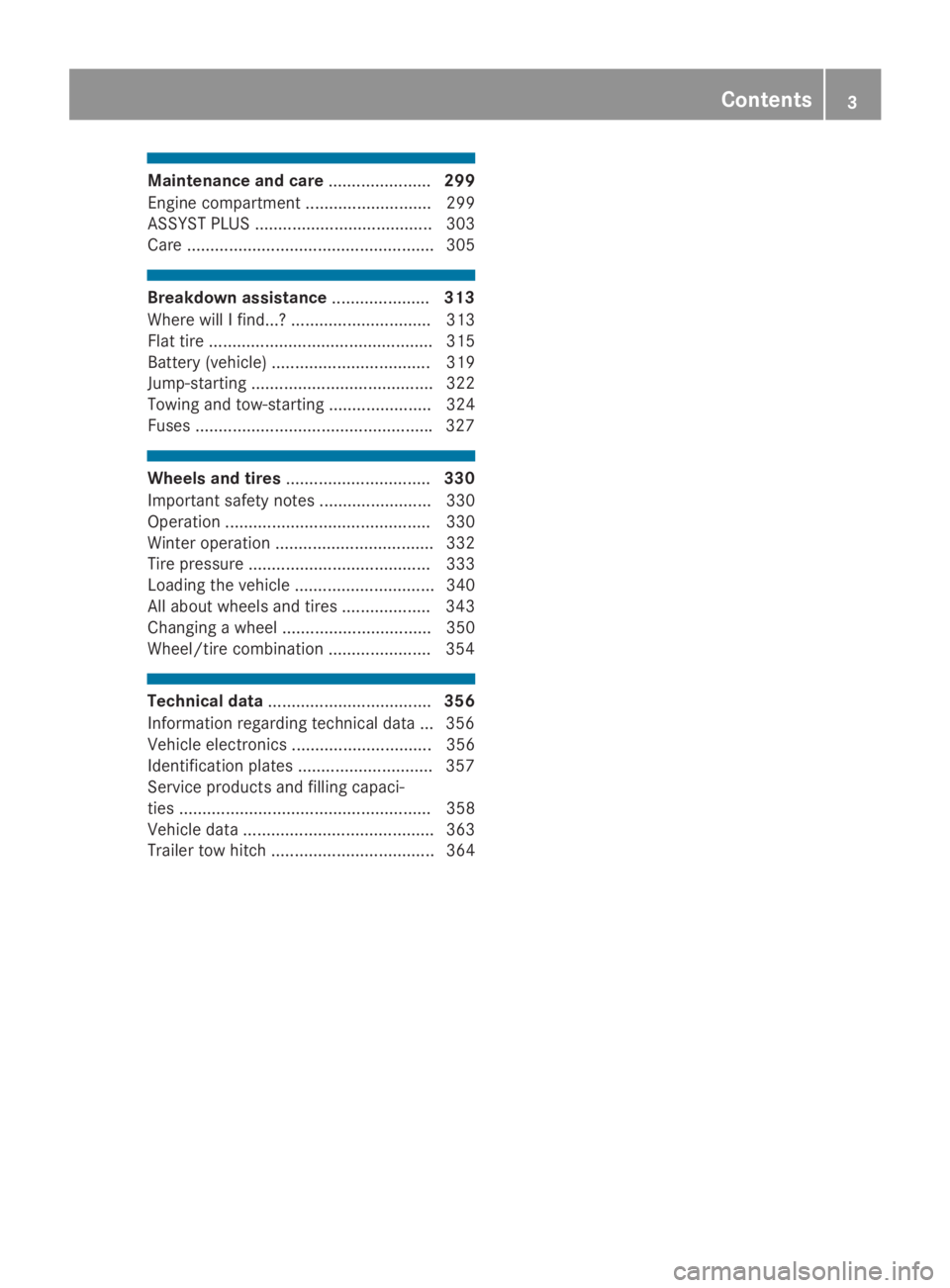
Maintenance and care......................299
Engine compartment ........................... 299
ASSYST PLUS ...................................... 303
Care ..................................................... 305
Breakdown assistance.....................313
Where will I find...? .............................. 313
Flat tire ................................................ 315
Battery (vehicle) .................................. 319
Jump-starting ....................................... 322
Towing and tow-starting ...................... 324
Fuses ...................................................327
Wheels and tires...............................330
Important safety notes ........................ 330
Operation ............................................ 330
Winter operation .................................. 332
Tire pressure ....................................... 333
Loading the vehicle .............................. 340
All about wheels and tires ................... 343
Changing a wheel ................................ 350
Wheel/tire combination ......................354
Technical data...................................356
Information regarding technical data ... 356
Vehicle electronics .............................. 356
Identification plates .............................357
Service products and filling capaci-
ties ...................................................... 358
Vehicle data ......................................... 363
Trailer tow hitch ................................... 364
Contents3
Page 11 of 370
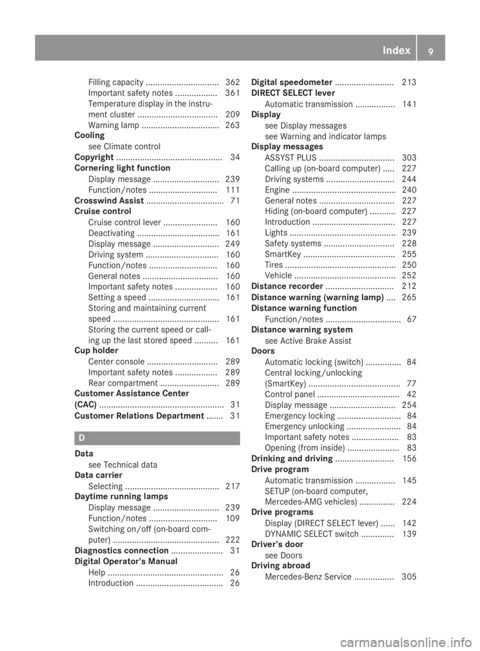
Filling capacity ............................... 362
Important safety notes .................. 361
Temperature display in the instru-
ment cluster .................................. 209
Warning lamp .................................263
Cooling
see Climate control
Copyright............................................. 34
Cornering light function
Display message ............................ 239
Function/notes .............................111
Crosswind Assist................................. 71
Cruise control
Cruise control lever ....................... 160
Deactivating ................................... 161
Display message ............................ 249
Driving system ............................... 160
Function/notes .............................160
General notes ................................ 160
Important safety notes .................. 160
Setting a speed .............................. 161
Storing and maintaining current
speed ............................................. 161
Storing the current speed or call-
ing up the last stored speed .......... 161
Cup holder
Center console .............................. 289
Important safety notes .................. 289
Rear compartment ......................... 289
Customer Assistance Center
(CAC)..................................................... 31
Customer Relations Department....... 31
D
Data
see Technical data
Data carrier
Selecting ........................................ 217
Daytime running lamps
Display message ............................ 239
Function/notes .............................109
Switching on/off (on-board com-
puter) ............................................. 222
Diagnostics connection......................31
Digital Operator's Manual
Help .................................................26
Introduction .....................................26
Digital speedometer.........................213
DIRECT SELECT lever
Automatic transmission ................. 141
Display
see Display messages
see Warning and indicator lamps
Display messages
ASSYST PLUS ................................ 303
Calling up (on-board computer) ..... 227
Driving systems .............................244
Engine ............................................ 240
General notes ................................ 227
Hiding (on-board computer) ........... 227
Introduction ................................... 227
Lights ............................................. 239
Safety systems .............................. 228
SmartKey ....................................... 255
Tires ............................................... 250
Vehicle ...........................................252
Distance recorder.............................212
Distance warning (warning lamp).... 265
Distance warning function
Function/notes ................................ 67
Distance warning system
see Active Brake Assist
Doors
Automatic locking (switch) ...............84
Central locking/unlocking
(SmartKey) .......................................77
Control panel ...................................42
Display message ............................ 254
Emergency locking ........................... 84
Emergency unlocking ....................... 84
Important safety notes.................... 83
Opening (from inside) ...................... 83
Drinking and driving......................... 156
Drive program
Automatic transmission ................. 145
SETUP (on-board computer,
Mercedes-AMG vehicles) ............... 224
Drive programs
Display (DIRECT SELECT lever) ...... 142
DYNAMIC SELECT switch .............. 139
Driver's door
see Doors
Driving abroad
Mercedes-Benz Service ................. 305
Index9
Page 23 of 370
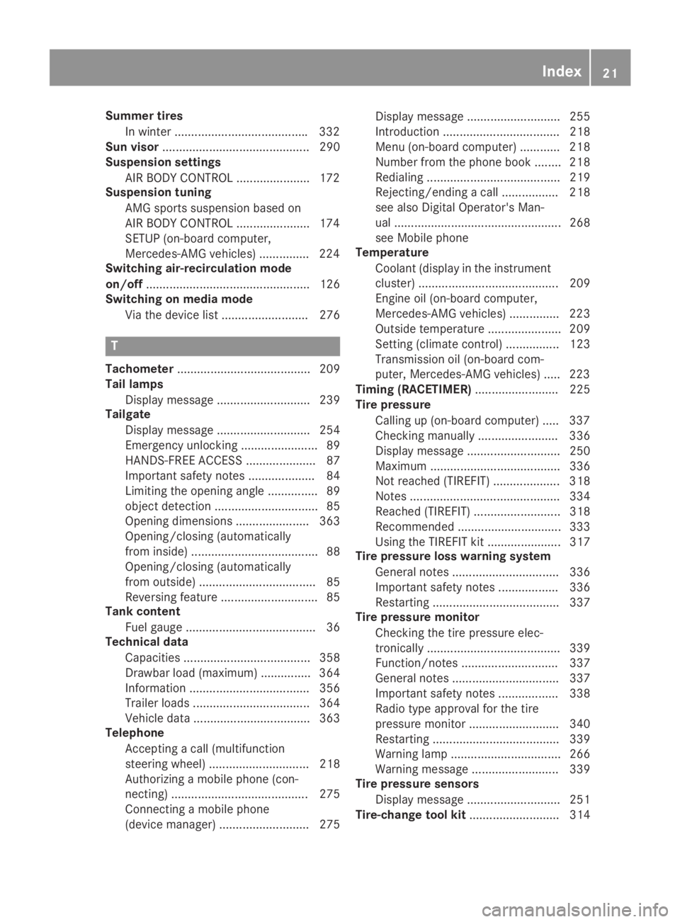
Summer tires
In winter ........................................332
Sun visor............................................ 290
Suspension settings
AIR BODY CONTROL ......................172
Suspension tuning
AMG sports suspension based on
AIR BODY CONTROL ......................174
SETUP (on-board computer,
Mercedes-AMG vehicles) ...............224
Switching air-recirculation mode
on/off................................................. 126
Switching on media mode
Via the device list.......................... 276
T
Tachometer........................................ 209
Tail lamps
Display message ............................ 239
Tailgate
Display message ............................ 254
Emergency unlocking ....................... 89
HANDS-FREE ACCESS ..................... 87
Important safety notes .................... 84
Limiting the opening angle ............... 89
object detection............................... 85
Opening dimensions ...................... 363
Opening/closing (automatically
from inside) ...................................... 88
Opening/closing (automatically
from outside) ................................... 85
Reversing feature ............................. 85
Tank content
Fuel gauge ....................................... 36
Technical data
Capacities ...................................... 358
Drawbar load (maximum) ............... 364
Information .................................... 356
Trailer loads................................... 364
Vehicle data ................................... 363
Telephone
Accepting a call (multifunction
steering wheel) .............................. 218
Authorizing a mobile phone (con-
necting) ......................................... 275
Connecting a mobile phone
(device manager) ........................... 275
Display message ............................ 255
Introduction ................................... 218
Menu (on-board computer) ............ 218
Number from the phone book ........ 218
Redialing ........................................ 219
Rejecting/ending a call ................. 218
see also Digital Operator's Man-
ual .................................................. 268
see Mobile phone
Temperature
Coolant (display in the instrument
cluster) .......................................... 209
Engine oil (on-board computer,
Mercedes-AMG vehicles) ............... 223
Outside temperature ...................... 209
Setting (climate control)................ 123
Transmission oil (on-board com-
puter, Mercedes-AMG vehicles) ..... 223
Timing (RACETIMER)......................... 225
Tire pressure
Calling up (on-board computer) ..... 337
Checking manually ........................ 336
Display message ............................ 250
Maximum ....................................... 336
Not reached (TIREFIT) .................... 318
Notes ............................................. 334
Reached (TIREFIT) .......................... 318
Recommended ............................... 333
Using the TIREFIT kit ...................... 317
Tire pressure loss warning system
General notes ................................ 336
Important safety notes .................. 336
Restarting ...................................... 337
Tire pressure monitor
Checking the tire pressure elec-
tronically ........................................ 339
Function/notes............................. 337
General notes ................................ 337
Important safety notes .................. 338
Radio type approval for the tire
pressure monitor ........................... 340
Restarting ...................................... 339
Warning lamp ................................. 266
Warning message .......................... 339
Tire pressure sensors
Display message ............................ 251
Tire-change tool kit........................... 314
Index21
Page 26 of 370
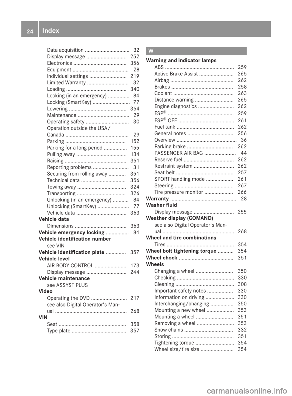
Data acquisition ............................... 32
Display message ............................ 252
Electronics .....................................356
Equipment ....................................... 28
Individual settings .......................... 219
Limited Warranty .............................32
Loading .......................................... 340
Locking (in an emergency) ............... 84
Locking (SmartKey) .......................... 77
Lowering ........................................ 354
Maintenance .................................... 29
Operating safety .............................. 30
Operation outside the USA/
Canada ............................................ 29
Parking .......................................... 152
Parking for a long period ................ 155
Pulling away................................... 134
Raising ........................................... 351
Reporting problems ......................... 31
Securing from rolling away ............ 351
Technical data ............................... 356
Towing away .................................. 324
Transporting .................................. 326
Unlocking (in an emergency) ........... 84
Unlocking (SmartKey) ...................... 77
Vehicle data ................................... 363
Vehicle data
Dimensions .................................... 363
Vehicle emergency locking................ 84
Vehicle identification number
see VIN
Vehicle identification plate.............. 357
Vehicle level
AIR BODY CONTROL ...................... 173
Display message ............................ 244
Vehicle maintenance
see ASSYST PLUS
Video
Operating the DVD ......................... 217
see also Digital Operator's Man-
ual .................................................. 268
VIN
Seat ............................................... 358
Type plate ...................................... 357
W
Warning and indicator lamps
ABS ................................................ 259
Active Brake Assist ........................ 265
Airbag ............................................ 262
Brakes ........................................... 258
Coolant .......................................... 263
Distance warning ........................... 265
Engine diagnostics ......................... 262
ESP®.............................................. 259
ESP®OFF ....................................... 261
Fuel tank ........................................ 262
General notes ................................ 256
Overview .......................................... 36
Parking brake ................................ 262
PASSENGER AIR BAG ...................... 44
Reserve fuel ................................... 262
Restraint system ............................ 262
Seat belt ........................................ 257
SPORT handling mode ................... 261
Steering ......................................... 267
Tire pressure monitor .................... 266
Warranty.............................................. 28
Washer fluid
Display message ............................ 255
Weather display (COMAND)
see also Digital Operator's Man-
ual .................................................. 268
Wheel and tire combinations
Tires ............................................... 354
Wheel bolt tightening torque........... 354
Wheel chock...................................... 351
Wheels
Changing a wheel.......................... 350
Checking ........................................ 330
Cleaning ......................................... 308
Important safety notes .................. 330
Information on driving .................... 330
Interchanging/changing ................ 350
Mounting a new wheel ................... 353
Mounting a wheel .......................... 351
Removing a wheel.......................... 353
Snow chains .................................. 332
Storing ........................................... 351
Tightening torque ........................... 354
Wheel size/tire size ....................... 354
24Index
Page 33 of 370
Diagnostics connection
The diagnostics connection is only intended forthe connection of diagnostic equipment at aqualified specialist workshop.
GWARNING
If you connect equipment to a diagnostics
connection in the vehicle, it may affect the
operation of vehicle systems. As a result, the
operating safety of the vehicle could be affec-
ted. There is a risk of an accident.
Only connect equipment to a diagnostics con-
nection in the vehicle, which is approved for
your vehicle by Mercedes-Benz.
GWARNING
Objects in the driver's footwell can restrict the
pedal travel or obstruct a depressed pedal.
The operating and road safety of the vehicle is
jeopardized. There is a risk of an accident.
Make sure that all objects in the vehicle are
stowed correctly, and that they cannot enter
the driver's footwell. Install the floormats
securely and as specified in order to ensure
sufficient clearance for the pedals. Do not use
loose floormats and do not place floormats on
top of one another.
!If the engine is switched off and equipmenton the diagnostics connection is used, thestarter battery may discharge.
Connecting equipment to the diagnostics con-nection can lead to emissions monitoring infor-mation being reset, for example. This may leadto the vehicle failing to meet the requirements ofthe next emissions test during the main inspec-tion.
Qualified specialist workshop
An authorized Mercedes-Benz Center is a quali-fied specialist workshop. It has the necessaryspecialist knowledge, tools and qualifications tocorrectly carry out the work required on yourvehicle. This is especially the case for work rel-evant to safety.
Observe the notes in the Maintenance Booklet.
Always have the following work carried out at anauthorized Mercedes-Benz Center:
Rwork relevant to safety
Rservice and maintenance work
Rrepair work
Ralterations, installation work and modifica-tions
Rwork on electronic components
Correct use
If you remove any warning stickers, you or oth-ers could fail to recognize certain dangers.Leave warning stickers in position.
Observe the following information when drivingyour vehicle:
Rthe safety notes in this manual
Rtechnical data for the vehicle
Rtraffic rules and regulations
Rlaws and safety standards pertaining to motorvehicles
Problems with your vehicle
If you should experience a problem with yourvehicle, particularly one that you believe mayaffect its safe operation, we urge you to contactan authorized Mercedes-Benz Center immedi-ately to have the problem diagnosed and recti-fied. If the problem is not resolved to your sat-isfaction, please discuss the problem again withan authorized Mercedes-Benz Center or, if nec-essary, contact us at one of the followingaddresses.
In the USA
Customer Assistance Center
Mercedes-Benz USA, LLC
3 Mercedes Drive
Montvale, NJ 07645-0350
In Canada
Customer Relations Department
Mercedes-Benz Canada, Inc.
98 Vanderhoof Avenue
Toronto, Ontario M4G 4C9
Reporting safety defects
USA only:
Operating safety31
Int roduction
Z
Page 34 of 370
The following text is reproduced as required ofall manufacturers under Title 49, Code of U.S.Federal Regulations, Part 575 pursuant to theNational Traffic and Motor Vehicle Safety Act of1966.
If you believe that your vehicle has a defectwhich could cause a crash or could cause injuryor death, you should immediately inform theNational Highway Traffic Safety Administration(NHTSA) in addition to notifying Mercedes-BenzUSA, LLC.
If NHTSA receives similar complaints, it mayopen an investigation, and if it finds that a safetydefect exists in a group of vehicles, it may ordera recall and remedy campaign. However, NHTSAcannot become involved in individual problemsbetween you, your dealer, or Mercedes-BenzUSA, LLC.
To contact NHTSA, you may call the VehicleSafety Hotline toll-free at 1-888-327-4236(TTY: 1-800-424-9153);go tohttp://www.safercar.gov; or write to: Administrator,NHTSA, 400 Seventh Street, SW., Washington,DC 20590.
You can also obtain other information aboutmotor vehicle safety from
http://www.safercar.gov
Limited Warranty
!Observe the notes in this Operator's Manualregarding the correct operation of your vehi-cle and possible damage to the vehicle. Dam-age to the vehicle which is caused by violationof these notes is not covered by theMercedes-Benz implied warranty or the newor used-vehicle warranty.
QR code for rescue card
The QR codes are secured in the fuel filler flapand on the opposite side on the B-pillar. In theevent of an accident, rescue services can usethe QR code to quickly find the appropriate res-cue card for your vehicle. The current rescuecard contains the most important informationabout your vehicle in a compact form, e.g. therouting of the electric cables.
You can find more information underwww.mercedes-benz.de/qr-code.
Data stored in the vehicle
Data storage
A wide range of electronic components in yourvehicle contain data memories.
These data memories temporarily or perma-nently store technical information about:
Rthe vehicle's operating state
Rincidents
Rmalfunctions
In general, this technical information docu-ments the state of a component, a module, asystem or the surroundings.
This includes, for example:
Roperating conditions of system components.For example, fluid levels
Rthe vehicle's status messages and those of itsindividual components, e.g. number of wheelrevolutions/speed, deceleration in move-ment, lateral acceleration, accelerator pedalposition
Rmalfunctions and defects in important systemcomponents, e.g. lights, brakes
Rvehicle reactions and operating conditions inspecial driving situations, e.g. air bag deploy-ment, intervention of stability control sys-tems
Rambient conditions, e.g. outside temperature
This data is of an exclusively technical natureand can be used to:
Rassist in recognizing and rectifying malfunc-tions and defects
Ranalyze vehicle functions, e.g. after an acci-dent
Roptimize vehicle functions
The data cannot be used to trace the vehicle'smovements.
When your vehicle is serviced, technical infor-mation can be read from the event data memoryand malfunction data memory.
Services include, for example:
Rrepair services
Rservice processes
Rwarranties
Rquality assurance
The vehicle is read out by employees of the ser-vice network (including the manufacturer) usingspecial diagnostic testers. More detailed infor-mation is obtained from it, if required.
32Data stored in the vehicle
Introduction
Page 35 of 370
After a malfunction has been rectified, the infor-mation is deleted from the malfunction memoryor is continually overwritten.
When operating the vehicle, situations are con-ceivable in which this technical data, in connec-tion with other information (if necessary, underconsultation with an authorized expert), couldbe traced to a person.
Examples include:
Raccident reports
Rdamage to the vehicle
Rwitness statements
Further additional functions that have been con-tractually agreed upon with the customer allowcertain vehicle data to be conveyed by the vehi-cle as well. The additional functions include, forexample, vehicle location in case of an emer-gency.
COMAND/mbrace
If the vehicle is equipped with COMAND ormbrace, additional data about the vehicle'soperation, the use of the vehicle in certain sit-uations, and the location of the vehicle may becompiled through COMAND or the mbrace sys-tem.
For additional information, please refer to theCOMAND User Manual or Digital Operator'sManual and/or the mbrace Terms and Condi-tions.
Event data recorders
This vehicle is equipped with an event datarecorder (EDR). This vehicle is equipped with anevent data recorder (EDR). The main purpose ofan EDR is to record, in certain crash or nearcrash-like situations, such as an air bag deploy-ment or hitting a road obstacle, data that willassist in understanding how a vehicle's systemsperformed. The EDR is designed to record datarelated to vehicle dynamics and safety systemsfor a short period of time, typically 30 secondsor less.
The EDR in this vehicle is designed to recordsuch data as:
RHow various systems in your vehicle wereoperating
RWhether or not the driver and passengersafety belts were buckled/fastened
RHow far (if at all) the driver was depressing theaccelerator and/or brake pedal and
RHow fast the vehicle was traveling
These data can help provide a better under-standing of the circumstances in which crashesand injuries occur. NOTE: EDR data are recordedby your vehicle only if a non-trivial crash situa-tion occurs; no data are recorded by the EDRunder normal driving conditions and no personaldata (e.g. name, gender, age and crash location)are recorded. However, other parties, such aslaw enforcement could combine the EDR datawith the type of personally identifying data rou-tinely acquired during a crash investigation.
Access to the vehicle and/or the EDR is neededto read data that is recorded by an EDR, andspecial equipment is required. In addition to thevehicle manufacturer, other parties that havethe special equipment, such as law enforce-ment, can read the information by accessing thevehicle or the EDR.
EDR data may be used in civil and criminal mat-ters as a tool in accident reconstruction, acci-dent claims and vehicle safety. Since the CrashData Retrieval CDR tool that is used to extractdata from the EDR is commercially available,Mercedes-Benz USA, LLC ("MBUSA") expresslydisclaims any and all liability arising from theextraction of this information by unauthorizedMercedes-Benz personnel.
MBUSA will not share EDR data with otherswithout the consent of the vehicle owners or, ifthe vehicle is leased, without the consent of thelessee. Exceptions to this representationinclude responses to subpoenas by law enforce-ment; by federal, state or local government; inconnection with or arising out of litigation involv-ing MBUSA or its subsidiaries and affiliates; or,as required by law.
Warning: The EDR is a component of theRestraint System Module. Tampering with, alter-ing, modifying or removing the EDR componentmay result in a malfunction of the Restraint Sys-tem Module and other systems.
State laws or regulations regarding EDRs thatconflict with federal regulation are pre-empted.This means that in the event of such conflict, thefederal regulation governs. As of February 2013,13 states have enacted laws relating to EDRs.
Data stored in the vehicle33
Introduction
Z
Page 58 of 370
and to have any malfunctioning air bagsrepaired. This will help to make sure the air bagscontinue to perform their protective function forthe vehicle occupants in the event of a crash.
GWARNING
Emergency Tensioning Devices that have
deployed pyrotechnically are no longer opera-
tional and are unable to perform their inten-
ded protective function. This poses an
increased risk of injury or even fatal injury.
Have pyrotechnically triggered Emergency
Tensioning Devices replaced immediately at a
qualified specialist workshop.
An electric motor is used by PRE-SAFE®to trig-ger the tightening of the seat belt in hazardoussituations. This procedure is reversible.
If Emergency Tensioning Devices are triggeredor air bags are deployed, you will hear a bang,and some powder may also be released. The�urestraint system warning lamp lights up.
Only in rare cases will the bang affect your hear-ing. The powder that is released generally doesnot constitute a health hazard, but it may causeshort-term breathing difficulties in people withasthma or other respiratory problems. Providedit is safe to do so, you should leave the vehicleimmediately or open the window in order to pre-vent breathing difficulties.
Air bags and pyrotechnic Emergency TensioningDevices (ETDs) contain perchlorate material,which may require special handling and regardfor the environment. National guidelines mustbe observed during disposal. In California, seewww.dtsc.ca.gov/HazardousWaste/Perchlorate/index.cfm.
Method of operation
During the first stage of a collision, the restraintsystem control unit evaluates important physi-cal data relating to vehicle deceleration or accel-eration, such as:
Rduration
Rdirection
Rintensity
Based on the evaluation of this data, therestraint system control unit triggers the Emer-gency Tensioning Devices during a head-on orrear-end collision.
An Emergency Tensioning Device can only betriggered, if:
Rthe ignition is switched on
Rthe components of the restraint system areoperational. You can find further informationunder "Restraint system warning lamp"(Ypage 44)
Rthe seat belt buckle tongue has engaged inthe belt buckle of the respective front seat
The Emergency Tensioning Devices in the rearpassenger compartment are triggered inde-pendently of the lock status of the seat belts.
If the restraint system control unit detects amore severe accident, further components ofthe restraint system are activated independ-ently of each other in certain frontal collisionsituations:
RFront air bags and driver's knee bag
RWindow curtain air bag, if the system deter-mines that deployment can offer additionalprotection to that provided by the seat belt
Depending on the person in the front-passengerseat, the front-passenger front air bag is eitherdisabled or enabled. The front-passenger frontair bag can be deployed in an accident only if thePASSENGER AIR BAG OFF indicator lamp is off.Observe the information on the PASSENGER AIRBAG indicator lamps (Ypage 44).
Your vehicle has two-stage front air bags. At thefirst deployment threshold the front air bag fillswith gas. If the second deployment threshold isthen reached within a few milliseconds, the frontair bag is filled with the maximum quantity ofgas.
The activation threshold of the Emergency Ten-sioning Devices and the air bags is determinedby evaluating the rate of vehicle deceleration oracceleration which occurs at various points inthe vehicle. This process is pre-emptive innature. Deployment should take place in goodtime at the start of the collision.
The rate of vehicle deceleration or accelerationand the direction of the force are essentiallydetermined by:
Rthe distribution of forces during the collision
Rthe collision angle
Rthe deformation characteristics of the vehicle
Rthe characteristics of the object with whichthe vehicle has collided
Factors which can only be seen and measuredafter a collision has occurred do not play a deci-sive role in the deployment of an air bag. Nor do
56Occupant safety
Safety
Page 204 of 370
the lines on the assistance graphic display areshown in green (Ypage 219). Active LaneKeeping Assist is ready for use.
XTo deactivate:press button�D.Indicator lamp�Cgoes out. The Active LaneKeeping Assist is deactivated. TheLaneLaneKeeping Assist OffKeeping Assist Offmessage appears inthe multifunction display.
Selecting Standard or Adaptive setting
XIn theDriveAssistDriveAssistmenu on the on-boardcomputer, select theActive Lane Keep‐Active Lane Keep‐ing Assisting Assistfunction (Ypage 221).
XSelect settingStandardStandardorAdaptiveAdaptive.WhenStandardStandardis selected, no warning vibra-tion occurs if:
Ryou switch on the turn signals. In this event,the warnings are suppressed for a certainperiod of time.
Ra driving safety system intervenes, such as
ABS, BAS or ESP®.
WhenAdaptiveAdaptiveis selected, no warning vibra-tion occurs if:
Ryou switch on the turn signals. In this event,the warnings are suppressed for a certainperiod of time.
Ra driving safety system intervenes, e.g.
ABS, BAS or ESP®.
Ryou accelerate hard, e.g. kickdown.
Ryou brake hard.
Ryou steer actively, e.g. swerve to avoid anobstacle or change lanes quickly.
Ryou cut the corner on a sharp bend.
To ensure that you are warned only when nec-essary and in good time if you cross the lanemarkings, the system detects certain conditionsand warns you accordingly.
The warning vibration occurs earlier if:
Ryou approach the outer lane marking on abend
Rthe road has very wide lanes, e.g. a freeway
Rthe system detects solid lane markings
The warning vibration occurs later if:
Rthe road has narrow lanes
Ryou cut the corner on a bend
Towing a trailer
When you attach a trailer, make sure you havecorrectly established the electrical connection.
This can be accomplished by checking the trailerlighting.
Towing a trailer
Important safety notes
GWARNING
Installing an unsuitable ball coupling may
result in overloading of the trailer tow hitch
and the rear axle. This applies especially if the
ball coupling in question is longer or angled
differently. This could seriously impair the
driving characteristics and the trailer can
come loose. There is a risk of an accident.
You should only ever install a ball coupling
that has the permissible dimensions and that
is designed to meet your trailer-towing
requirements. Do not modify the ball coupling
or the trailer tow hitch.
You will find the values approved by the manu-facturer on the vehicle identification plates andthose for the towing vehicle under "Technicaldata" (Ypage 364).
GWARNING
When the vehicle/trailer combination begins
to lurch, you could lose control of it. The vehi-
cle/trailer combination could even rollover.
There is a risk of an accident.
On no account should you attempt to
straighten up the vehicle/trailer combination
by increasing the speed. Reduce vehicle
speed and do not countersteer. Apply the
brake as necessary.
!If you have a trailer tow hitch retrofitted,changes to the engine cooling system may benecessary, depending on the vehicle type.
If you have a trailer tow hitch retrofitted,observe the anchorage points on the chassisframe.
The installation of a trailer tow hitch is only per-missible if a towing weight is specified in yourvehicle documents. If this is not the case, thenthe vehicle is not approved for the towing of atrailer.
202Towing a trailer
Driving an d parking
Page 205 of 370
For more information, please contact a qualifiedspecialist workshop.
Please observe the manufacturer's operatinginstructions for the trailer coupling if a detach-able trailer coupling is used.
Couple and uncouple the trailer carefully. If youdo not couple the trailer to the towing vehiclecorrectly, the trailer could become detached.
Make sure that the following values are notexceeded:
Rthe permissible trailer drawbar noseweight
Rthe permissible trailer load
Rthe permissible rear axle load of the towingvehicle
Rthe maximum permissible gross vehicleweight of both the towing vehicle and thetrailer
The applicable permissible values, which mustnot be exceeded, can be found:
Rin the vehicle documents
Ron the type plate for the trailer
Ron the vehicle identification plate
If the values differ, the lowest value applies.
When towing a trailer, your vehicle's handlingcharacteristics will be different in comparisonwith when driving without a trailer.
The vehicle/trailer combination:
Ris heavier
Ris restricted in its acceleration and gradient-climbing capability
Rhas an increased braking distance
Ris affected more by strong crosswinds
Rdemands more sensitive steering
Rhas a larger turning circle
This could impair the handling characteristics.
When towing a trailer, always adjust your speedto the current road and weather conditions. Donot exceed the maximum permissible speed foryour vehicle/trailer combination.
Notes on towing a trailer
General notes
RDo not exceed the maximum permissiblespeed for vehicle/trailer combinations in therelevant country.
This lowers the risk of an accident.
ROnly install an approved trailer coupling onyour vehicle.
Further information on availability and oninstallation is available from any authorizedMercedes-Benz Center.
RThe bumpers of your vehicle are not suitablefor installing detachable trailer couplings.
RDo not install hired trailer couplings or otherdetachable trailer couplings on the bumpersof your vehicle.
RIf you no longer need the ball coupling,remove it from the ball coupling recess. Thiswill reduce the risk of damage to the ball cou-pling.
When towing a trailer, set the tire pressure onthe rear axle of the towing vehicle for a maxi-mum load; see the tire pressure table in the fuelfiller flap (Ypage 348).
Please note that when towing a trailer, the fol-lowing driving systems have limited availabilityor are not available at all:
RPARKTRONIC (Ypage 179)
RBlind Spot Assist (Ypage 193)
RActive Lane Keeping Assist (Ypage 200)
On vehicles without level control, the height ofthe ball coupling will alter according to the loadplaced on the vehicle. If necessary, use a trailerwith a height-adjustable drawbar.
You will find permissible trailer loads under"Technical data" (Ypage 364).
Driving tips
Observe the information on ESP®trailer stabili-zation (Ypage 71) and on pulling away with atrailer (Ypage 135).
The maximum permissible speed for vehicle/trailer combinations depends on the type oftrailer. Before beginning the journey, check thetrailer's documents to see what the maximumpermitted speed is. Observe the maximum per-missible speed in the relevant country.
For certain Mercedes-Benz vehicles, the maxi-mum permissible rear axle load is increasedwhen towing a trailer. See the "Technical data"section to find out whether this applies to yourvehicle (Ypage 365). In the event of increasedrear axle load, the vehicle/trailer combinationmay not exceed a maximum speed of 60 mph(100 km/h) for reasons concerning the operat-ing permit. This also applies in countries in
Towing a trailer203
Driving and parking
Z