tow MERCEDES-BENZ GLC COUPE 2016 Owners Manual
[x] Cancel search | Manufacturer: MERCEDES-BENZ, Model Year: 2016, Model line: GLC COUPE, Model: MERCEDES-BENZ GLC COUPE 2016Pages: 389, PDF Size: 7.34 MB
Page 355 of 389
The battery must be connected and charged.
Otherwise, you:
R cannot turn the key to position 2in the igni-
tion lock
R cannot release the electric parking brake
R cannot shift the automatic transmission to
position N
Deactivate the automatic locking feature before towing the vehicle (Y page 89). You could oth-
erwise be locked out when pushing or towing
the vehicle.
Deactivate tow-away protection before the vehi-
cle is towed away (Y page 80).Fitting/removing the towing eye
Fitting the towing eye G
WARNING
The exhaust tail pipe may be extremely hot.
There is a risk of burning when removing the
rear cover.
Do not touch the exhaust tail pipe. Use
extreme caution when removing the rear
cover. Mercedes-AMG vehicles All other vehicles
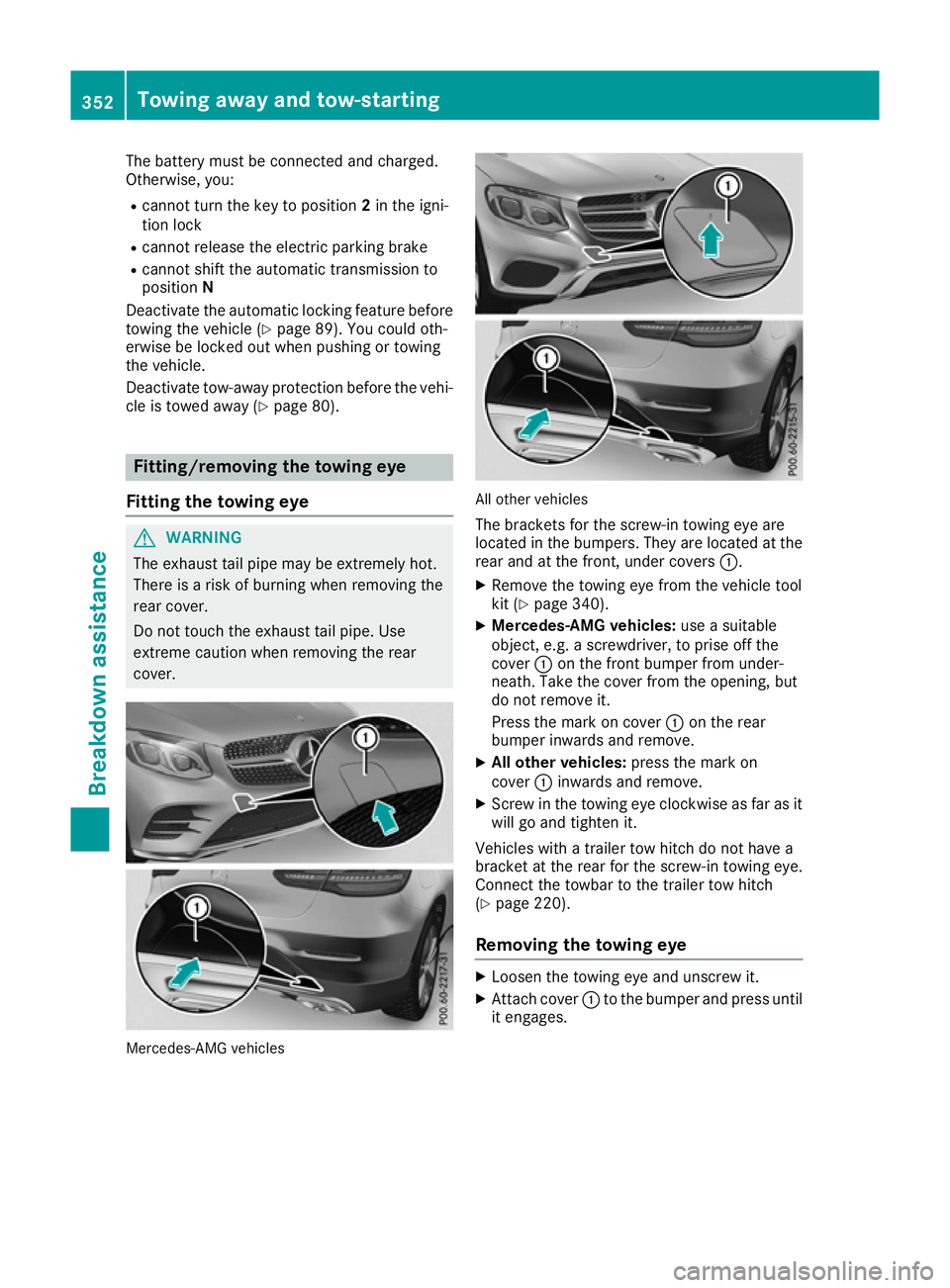
The brackets for the screw-in towing eye are
located in the bumpers. They are located at therear and at the front, under covers :.
X Remove the towing eye from the vehicle tool
kit (Y page 340).
X Mercedes-AMG vehicles: use a suitable
object, e.g. a screwdriver, to prise off the
cover :on the front bumper from under-
neath. Take the cover from the opening, but
do not remove it.
Press the mark on cover :on the rear
bumper inwards and remove.
X All other vehicles: press the mark on
cover :inwards and remove.
X Screw in the towing eye clockwise as far as it
will go and tighten it.
Vehicles with a trailer tow hitch do not have a
bracket at the rear for the screw-in towing eye.
Connect the towbar to the trailer tow hitch
(Y page 220).
Removing the towing eye X
Loosen the towing eye and unscrew it.
X Attach cover :to the bumper and press until
it engages. 352
Towing away and tow-startingBreakdown assistance
Page 356 of 389
Towing the vehicle with both axles on
the ground
The automatic transmission automatically shifts to position Pwhen you open the driver's or front-
passenger door or when you remove the key
from the ignition lock. In order to ensure that the
automatic transmission stays in position N
when the vehicle is being towed, you must
observe the following points:
X Make sure that the vehicle is stationary.
X Turn the key to position 2in the ignition lock.
X Depress the brake pedal and keep it
depressed.
X Shift the automatic transmission to position
N.
X Leave the key in position 2in the ignition lock.
X Release the brake pedal.
X Release the electric parking brake.
X Switch on the hazard warning lamps
(Y page 117).
In order to signal a change of direction when
towing the vehicle with the hazard warning
lamps switched on, use the combination switch
as usual. In this case, only the turn signals for
the desired direction flash. When you reset the
combination switch, the hazard warning lamps
start flashing again. Transporting the vehicle
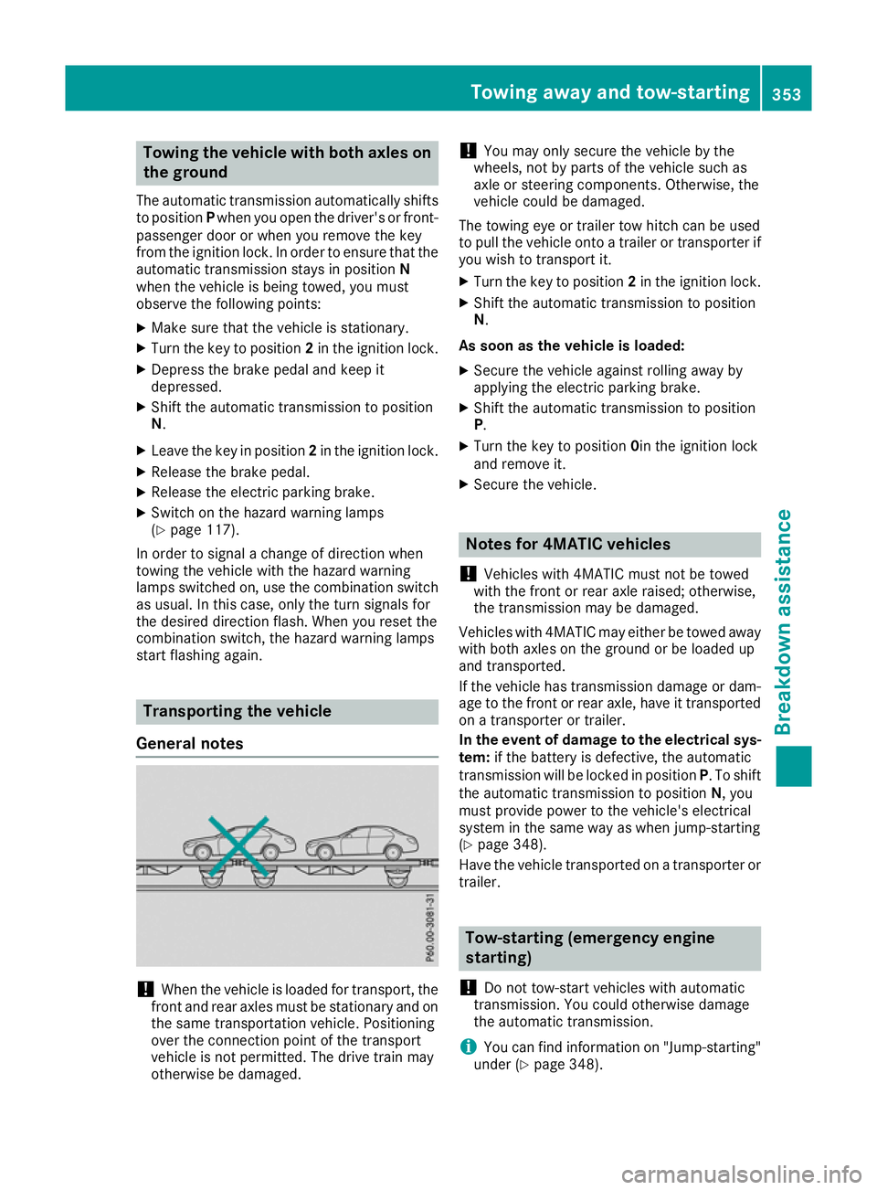
General notes !
When the vehicle is loaded for transport, the
front and rear axles must be stationary and on
the same transportation vehicle. Positioning
over the connection point of the transport
vehicle is not permitted. The drive train may
otherwise be damaged. !
You may only secure the vehicle by the
wheels, not by parts of the vehicle such as
axle or steering components. Otherwise, the
vehicle could be damaged.
The towing eye or trailer tow hitch can be used
to pull the vehicle onto a trailer or transporter if
you wish to transport it.
X Turn the key to position 2in the ignition lock.
X Shift the automatic transmission to position
N.
As soon as the vehicle is loaded:
X Secure the vehicle against rolling away by
applying the electric parking brake.
X Shift the automatic transmission to position
P.
X Turn the key to position 0in the ignition lock
and remove it.
X Secure the vehicle. Notes for 4MATIC vehicles
! Vehicles with 4MATIC must not be towed
with the front or rear axle raised; otherwise,
the transmission may be damaged.
Vehicles with 4MATIC may either be towed away
with both axles on the ground or be loaded up
and transported.
If the vehicle has transmission damage or dam- age to the front or rear axle, have it transportedon a transporter or trailer.
In the event of damage to the electrical sys-
tem: if the battery is defective, the automatic
transmission will be locked in position P. To shift
the automatic transmission to position N, you
must provide power to the vehicle's electrical
system in the same way as when jump-starting
(Y page 348).
Have the vehicle transported on a transporter or
trailer. Tow-starting (emergency engine
starting)
! Do not tow-start vehicles with automatic
transmission. You could otherwise damage
the automatic transmission.
i You can find information on "Jump-starting"
under (Y page 348). Towing away and tow-starting
353Breakdown assistance Z
Page 357 of 389
Fuses
Important safety notes
G
WARNING
If you manipulate, bridge or replace a faulty
fuse with a fuse of a higher amperage, the
electric cables could be overloaded. This may result in a fire. There is a risk of an accident
and injury.
Always replace faulty fuses with specified new fuses of the correct amperage.
Blown fuses must be replaced with fuses of the same rating, which you can recognise by the
colour and fuse rating. The fuse ratings are listed
in the fuse allocation chart.
The fuse allocation chart is on the fuse box in the luggage compartment (Y page 355).
If the newly inserted fuse also blows, have the
cause traced and rectified at a qualified special-
ist workshop, e.g. a Mercedes-Benz Service
Centre.
! Only use fuses that have been approved for
Mercedes-Benz vehicles and which have the
correct fuse rating for the system concerned.
Otherwise, components or systems could be
damaged.
! Make sure that no moisture can enter the
fuse box when the cover is open.
! When closing the cover, make sure that it is
lying correctly on the fuse box. Moisture seep-
ing in or dirt could otherwise impair the oper- ation of the fuses.
The fuses in your vehicle disconnect faulty cir-
cuits. If a fuse blows, all the components on the circuit and their functions will fail. Before replacing a fuse
Observe the important safety notes
(Y page 354)
X Switch off the engine.
X Switch off all electrical consumers. X
Make sure that the ignition is switched off
(Y page 144).
or
X When using the key, turn the key to position 0
in the ignition lock and remove it
(Y page 144).
X Secure the vehicle against rolling away
(Y page 167).
All indicator lamps on the instrument cluster
must be off.
The fuses are located in various fuse boxes:
R Fuse box on the driver's side of the dashboard
R Fuse box in the front-passenger footwell
R Fuse box in the engine compartment on the
driver's side
R Fuse box under the luggage compartment
floor on the right-hand side of the vehicle,
when viewed in the direction of travel Dashboard fuse box
The fuse box is under a cover on the side of the dashboard. You can obtain further information
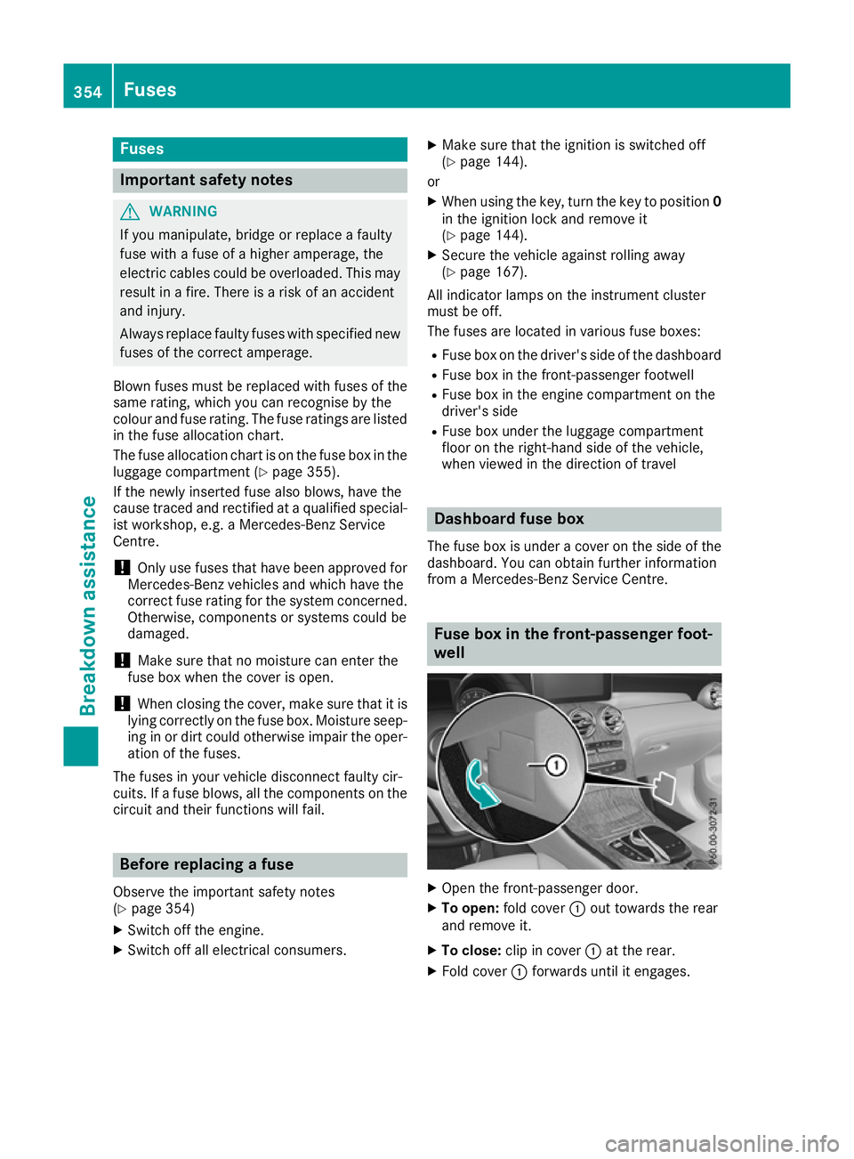
from a Mercedes-Benz Service Centre. Fuse box in the front-passenger foot-
well
X
Open the front-passenger door.
X To open: fold cover :out towards the rear
and remove it.
X To close: clip in cover :at the rear.
X Fold cover :forwards until it engages. 354
FusesBreakdown assistance
Page 364 of 389
Important safety notes
The tyre pressure warning system does not warn
you of an incorrectly set tyre pressure. Observe
the notes on the recommended tyre pressure
(Y page 359).
The tyre pressure loss warning system does not
replace the need to regularly check the tyre
pressure. An even loss of pressure on several
tyres at the same time cannot be detected by
the tyre pressure loss warning system.
The tyre pressure loss warning system is not
able to warn you of a sudden loss of air, e.g. if the
tyre is penetrated by a foreign object. In the
event of a sudden loss of air, bring the vehicle to
a halt by braking carefully. Avoid abrupt steering manoeuvres.
The function of the tyre pressure loss warning
system is limited or delayed if:
R snow chains are fitted on your vehicle
R road conditions are wintry
R you are driving on a loose surface (e.g. sand or
gravel)
R you adopt a very sporty driving style (corner-
ing at high speeds or driving with high rates of
acceleration)
R you are towing a very heavy or large trailer
R you are driving with a heavy load (in the vehi-
cle or on the roof)
Restarting the tyre pressure loss warn-
ing system Restart the tyre pressure loss warning system if
you have:
R changed the tyre pressure
R changed the wheels or tyres
R fitted new wheels or tyres
X Before restarting, make sure that the tyre
pressures are set properly on all four tyres for
the respective operating conditions. The rec-
ommended tyre pressures can be found in the
tyre pressure table on the fuel filler flap.
The tyre pressure loss warning system can
only give reliable warnings if you have set the correct tyre pressure. If an incorrect tyre
pressure is set, this incorrect value will be
monitored.
X Observe the notes in the section on tyre pres-
sure (Y page 359). X
Make sure that the key is in position 2in the
ignition lock (Y page 144).
X Press òon the steering wheel to call up
the menu list.
X Press 9or: on the steering wheel to
select the Service
Service menu.
X Confirm by pressing aon the steering
wheel.
X Select Tyre pressure Tyre pressure with9 or:.
X Press ato confirm.
The Run
Run Flat
Flat Indicator
Indicator active
activeRestart
Restart
with OK
with OK message is shown in the multifunc-
tion display.
If you wish to confirm the restart: X Press the abutton.
The Tyre pressure now OK?
Tyre pressure now OK? message is
shown in the multifunction display.
X Select Yes
Yes with 9 or:.
X Press ato confirm.
The Run Flat Indicator restarted
Run Flat Indicator restarted mes-
sage is shown in the multifunction display.
After a teach-in period, the tyre pressure loss
warning system will monitor the set tyre pres- sures of all four tyres.
If you wish to cancel the restart:
X Press the %button.
or
X If the Tyre pressure now OK? Tyre pressure now OK? message
appears, select Cancel
Cancelwith9 or:.
X Press ato confirm.
The tyre pressure values stored at the last
restart will continue to be monitored. Tyre pressure monitor
General notes If a tyre pressure monitor system is fitted, the
vehicle's wheels have sensors fitted that moni-
tor the tyre pressures in all four tyres. The tyre
pressure monitor warns you if the pressure
drops in one or more of the tyres. The tyre pres- sure monitor functions only if the corresponding
sensors are fitted to all wheels.
Information on tyre pressures is shown on the
multifunction display. After a few minutes of
driving, the current tyre pressure of each tyre is
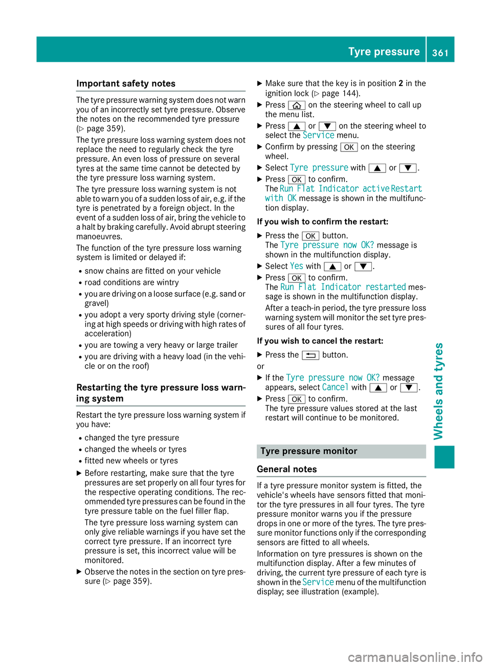
shown in the Service Servicemenu of the multifunction
display; see illustration (example). Tyre pressure
361Wheels and tyres Z
Page 371 of 389
X
Clean the wheel and wheel hub contact sur-
faces.
X Slide the wheel to be mounted onto the cen-
tring pin and push it on.
X Tighten the wheel bolts until they are finger-
tight.
X Unscrew the centring pin.
X Tighten the last wheel bolt until it is finger-
tight.
Lowering the vehicle G
WARNING
The wheels could work loose if the wheel nuts and bolts are not tightened to the specified
tightening torque. There is a risk of accident.
Have the tightening torque immediately
checked at a qualified specialist workshop
after a wheel is changed.
X Place the ratchet ring spanner onto the hex-
agon nut of the jack so that the letters ABare
visible.
X Turn the ratchet ring spanner until the vehicle
is once again standing firmly on the ground.
X Place the jack to one side. X
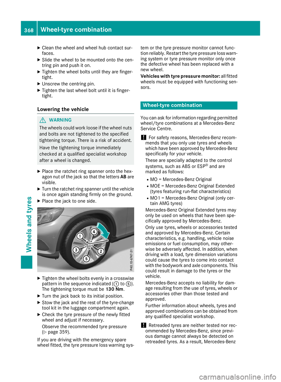
Tighten the wheel bolts evenly in a crosswise
pattern in the sequence indicated (: toA).
The tightening torque must be 130 Nm.
X Turn the jack back to its initial position.
X Stow the jack and the rest of the tyre-change
tool kit in the luggage compartment again.
X Check the tyre pressure of the newly fitted
wheel and adjust if necessary.
Observe the recommended tyre pressure
(Y page 359).
If you are driving with the emergency spare
wheel fitted, the tyre pressure loss warning sys- tem or the tyre pressure monitor cannot func-
tion reliably. Restart the tyre pressure loss warn- ing system or tyre pressure monitor only once
the defective wheel has been replaced with a
new wheel.
Vehicles with tyre pressure monitor: all fitted
wheels must be equipped with functioning sen-
sors. Wheel-tyre combination
You can ask for information regarding permitted
wheel/tyre combinations at a Mercedes-Benz
Service Centre.
! For safety reasons, Mercedes-Benz recom-
mends that you only use tyres and wheels
which have been approved by Mercedes-Benz specifically for your vehicle.
These are specially adapted to the control
systems, such as ABS or ESP ®
and are
marked as follows:
R MO = Mercedes-Benz Original
R MOE = Mercedes-Benz Original Extended
(tyres featuring run-flat characteristics)
R MO1 = Mercedes-Benz Original (only cer-
tain AMG tyres)
Mercedes-Benz Original Extended tyres may
only be used on wheels that have been spe-
cifically approved by Mercedes-Benz.
Only use tyres, wheels or accessories tested
and approved by Mercedes-Benz. Certain
characteristics, e.g. handling, vehicle noise
emissions or fuel consumption, may other-
wise be adversely affected. In addition, when driving with a load, tyre dimension variations
could cause the tyres to come into contact
with the bodywork and axle components. This
could result in damage to the tyres or the
vehicle.
Mercedes-Benz accepts no liability for dam-
age resulting from the use of tyres, wheels or accessories other than those tested and
approved.
Further information about wheels, tyres and
approved combinations can be obtained from
any qualified specialist workshop.
! Retreaded tyres are neither tested nor rec-
ommended by Mercedes-Benz, since previ-
ous damage cannot always be detected on
retreaded tyres. As a result, Mercedes-Benz 368
Wheel-tyre combinationWheels and tyres
Page 376 of 389
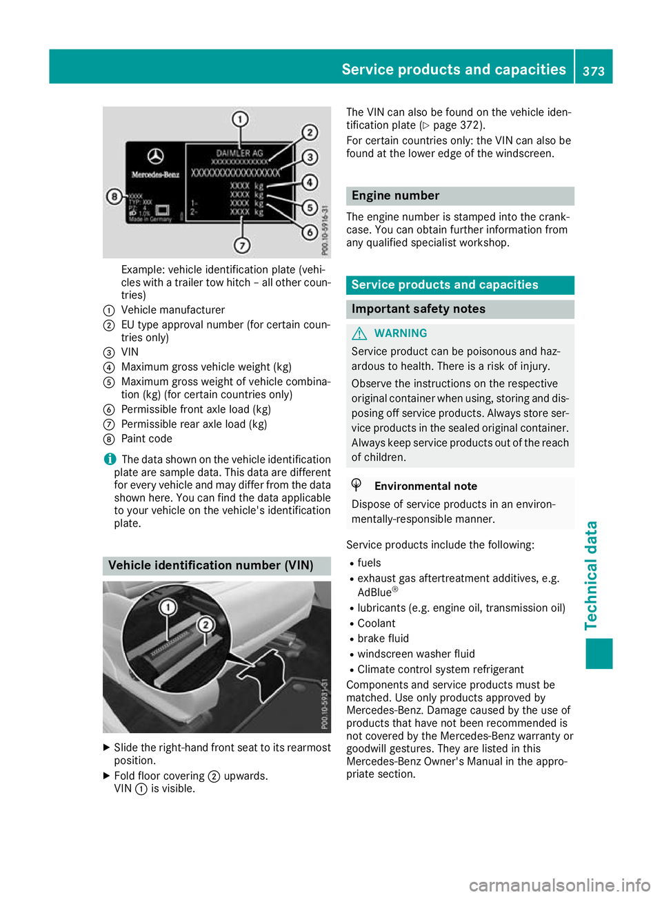
Example: vehicle identification plate (vehi-
cles with a trailer tow hitch – all other coun- tries)
: Vehicle manufacturer
; EU type approval number (for certain coun-
tries only)
= VIN
? Maximum gross vehicle weight (kg)
A Maximum gross weight of vehicle combina-
tion (kg) (for certain countries only)
B Permissible front axle load (kg)
C Permissible rear axle load (kg)
D Paint code
i The data shown on the vehicle identification
plate are sample data. This data are different for every vehicle and may differ from the data
shown here. You can find the data applicable to your vehicle on the vehicle's identification
plate. Vehicle identification number (VIN)
X
Slide the right-hand front seat to its rearmost
position.
X Fold floor covering ;upwards.
VIN :is visible. The VIN can also be found on the vehicle iden-
tification plate (Y
page 372).
For certain countries only: the VIN can also be
found at the lower edge of the windscreen. Engine number
The engine number is stamped into the crank-
case. You can obtain further information from
any qualified specialist workshop. Service products and capacities
Important safety notes
G
WARNING
Service product can be poisonous and haz-
ardous to health. There is a risk of injury.
Observe the instructions on the respective
original container when using, storing and dis- posing off service products. Always store ser-
vice products in the sealed original container. Always keep service products out of the reach
of children. H
Environmental note
Dispose of service products in an environ-
mentally-responsible manner.
Service products include the following:
R fuels
R exhaust gas aftertreatment additives, e.g.
AdBlue ®
R lubricants (e.g. engine oil, transmission oil)
R Coolant
R brake fluid
R windscreen washer fluid
R Climate control system refrigerant
Components and service products must be
matched. Use only products approved by
Mercedes-Benz. Damage caused by the use of
products that have not been recommended is
not covered by the Mercedes-Benz warranty or
goodwill gestures. They are listed in this
Mercedes-Benz Owner's Manual in the appro-
priate section. Service products and capacities
373Technical data Z
Page 383 of 389
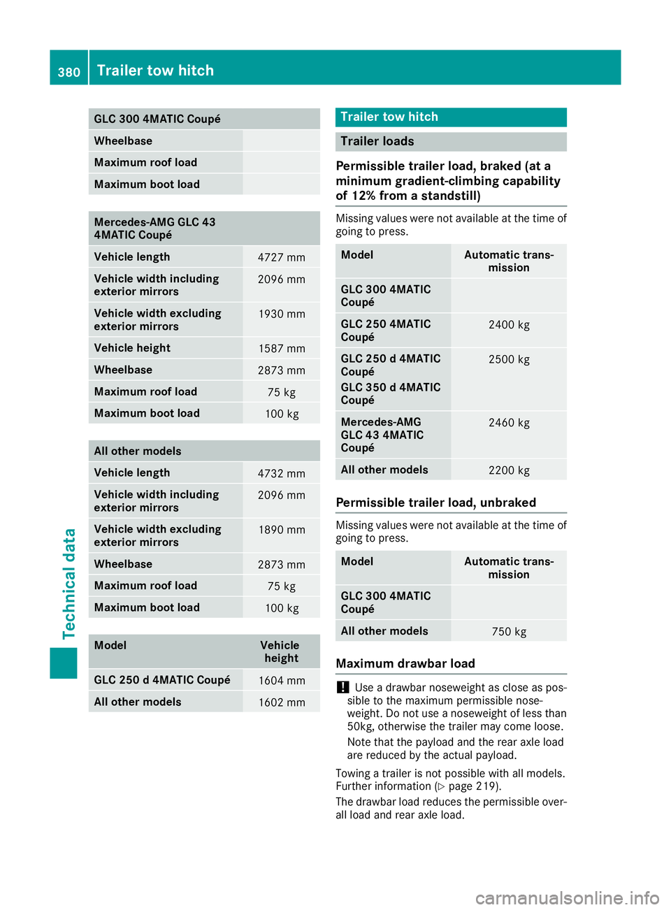
GLC 300 4MATIC Coupé
Wheelbase
Maximum roof load
Maximum boot load
Mercedes-AMG GLC 43
4MATIC Coupé
Vehicle length
4727 mm
Vehicle width including
exterior mirrors
2096 mm
Vehicle width excluding
exterior mirrors
1930 mm
Vehicle height
1587 mm
Wheelbase
2873 mm
Maximum roof load
75 kg
Maximum boot load
100 kg
All other models
Vehicle length
4732 mm
Vehicle width including
exterior mirrors
2096 mm
Vehicle width excluding
exterior mirrors
1890 mm
Wheelbase
2873 mm
Maximum roof load
75 kg
Maximum boot load
100 kg
Model Vehicle
height GLC 250 d 4MATIC Coupé
1604 mm
All other models
1602 mm Trailer tow hitch
Trailer loads
Permissible trailer load, braked (at a
minimum gradient-climbing capability
of 12% from a standstill) Missing values were not available at the time of
going to press. Model Automatic trans-
mission GLC 300 4MATIC
Coupé
GLC 250 4MATIC
Coupé
2400 kg
GLC 250 d 4MATIC
Coupé
GLC 350 d 4MATIC
Coupé
2500 kg
Mercedes-AMG
GLC 43 4MATIC
Coupé
2460 kg
All other models
2200 kg
Permissible trailer load, unbraked
Missing values were not available at the time of
going to press. Model Automatic trans-
mission GLC 300 4MATIC
Coupé
All other models
750 kg
Maximum drawbar load
!
Use a drawbar noseweight as close as pos-
sible to the maximum permissible nose-
weight. Do not use a noseweight of less than
50kg, otherwise the trailer may come loose.
Note that the payload and the rear axle load
are reduced by the actual payload.
Towing a trailer is not possible with all models.
Further information (Y page 219).
The drawbar load reduces the permissible over- all load and rear axle load. 380
Trailer tow hitchTechnical data
Page 384 of 389
The drawbar load acts from above onto the ball
head on the trailer tow hitch.
The drawbar load is not included in the trailer
load.
Missing values were not available at the time of
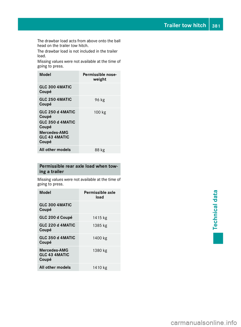
going to press. Model Permissible nose-
weight GLC 300 4MATIC
Coupé
GLC 250 4MATIC
Coupé
96 kg
GLC 250 d 4MATIC
Coupé
GLC 350 d 4MATIC
Coupé
Mercedes-AMG
GLC 43 4MATIC
Coupé
100 kg
All other models
88 kg
Permissible rear axle load when tow-
ing a trailer
Missing values were not available at the time of
going to press. Model Permissible axle
load GLC 300 4MATIC
Coupé
GLC 200 d Coupé
1415 kg
GLC 220 d 4MATIC
Coupé
1385 kg
GLC 350 d 4MATIC
Coupé
1400 kg
Mercedes-AMG
GLC 43 4MATIC
Coupé
1380 kg
All other models
1410 kg Trailer tow hitch
381Technical data Z