mirror MERCEDES-BENZ GLC COUPE 2016 Owner's Guide
[x] Cancel search | Manufacturer: MERCEDES-BENZ, Model Year: 2016, Model line: GLC COUPE, Model: MERCEDES-BENZ GLC COUPE 2016Pages: 389, PDF Size: 7.34 MB
Page 207 of 389
R
a split screen with top view and the image
from the front camera or
R a split screen with top view and the image
from the rear view camera
X To switch off: press button:again.
Switching on the 360° camera using
reverse gear You can show images from the 360° camera
automatically by engaging reverse gear.
X Make sure that the Activation by R gear
Activation by R gear
function is selected in the multimedia system (see Digital Owner's Manual).
X To show the 360° camera image: engage
reverse gear.
The multimedia system shows the area
behind the vehicle in split-screen mode. You
see the top view of the vehicle and the image
from the reversing camera.
You cannot stop the 360° camera display if
reverse gear is engaged.
Selecting the split-screen view or full-
screen mode Switching between split screen views:
X To switch to the line with the vehicle icons:
slide 5the controller.
X To select a vehicle icon: turn the controller.
Switching to full-screen mode:
X Turn and press 180° 180°view
viewwith the controller.
The full-screen option is available only in the fol- lowing views:
R top view with image from the reversing cam-
era
R top view with image from the front camera
Multimedia system display Important safety notes
The camera system may show a distorted view
of obstacles, show them incorrectly or not show them at all. Obstacles in the following locations
are not shown by the system:
R under the front and rear bumpers
R very close to the front and rear bumpers
R in the area immediately above the recessed
tailgate handle R
very close to the exterior mirrors
R in the transitional areas between the various
cameras in the virtual top view
! Objects not at ground level may appear to
be further away than they actually are, e.g.:
R the bumper of a parked vehicle
R the drawbar of a trailer
R the ball coupling of a trailer tow hitch
R the rear section of an HGV
R a slanted post
Use the guidelines only for orientation.
Approach objects no further than the bottom- most guideline.
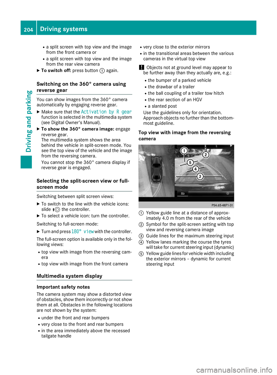
Top view with image from the reversing
camera :
Yellow guide line at a distance of approx-
imately 4.0 m from the rear of the vehicle
; Symbol for the split-screen setting with top
view and reversing camera image
= Guide lines for the maximum steering input
? Yellow lanes marking the course the tyres
will take for current steering input (dynamic)
A Yellow guide lines for vehicle width including
the exterior mirrors – dynamic for current
steering input 204
Driving systemsDriving and parking
Page 208 of 389
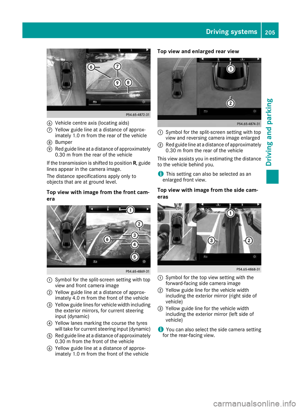
B
Vehicle centre axis (locating aids)
C Yellow guide line at a distance of approx-
imately 1.0 m from the rear of the vehicle
D Bumper
E Red guide line at a distance of approximately
0.30 m from the rear of the vehicle
If the transmission is shifted to position R, guide
lines appear in the camera image.
The distance specifications apply only to
objects that are at ground level.
Top view with image from the front cam-
era :
Symbol for the split-screen setting with top
view and front camera image
; Yellow guide line at a distance of approx-
imately 4.0 m from the front of the vehicle
= Yellow guide lines for vehicle width including
the exterior mirrors, for current steering
input (dynamic)
? Yellow lanes marking the course the tyres
will take for current steering input (dynamic)
A Red guide line at a distance of approximately
0.30 m from the front of the vehicle
B Yellow guide line at a distance of approx-
imately 1.0 m from the front of the vehicle Top view and enlarged rear view
:
Symbol for the split-screen setting with top
view and reversing camera image enlarged
; Red guide line at a distance of approximately
0.30 m from the rear of the vehicle
This view assists you in estimating the distance to the vehicle behind you.
i This setting can also be selected as an
enlarged front view.
Top view with image from the side cam-
eras :
Symbol for the top view setting with the
forward-facing side camera image
; Yellow guide line for the vehicle width
including the exterior mirror (right side of
vehicle)
= Yellow guide line for the vehicle width
including the exterior mirror (left side of
vehicle)
i You can also select the side camera setting
for the rear-facing view. Driving systems
205Driving and parking Z
Page 213 of 389
Lane Tracking package
General notes The Lane Tracking package consists of Blind
Spot Assist (Y page 210) and Lane Keeping
Assist (Y page 211).
Blind Spot Assist General notes
Blind Spot Assist monitors the areas on either
side of the vehicle that are not visible to the
driver with two lateral, rear-facing radar sen-
sors. A warning lamp lights up on the exterior
mirror and draws your attention to vehicles
detected in the monitored area. If you then
switch on the corresponding turn signal to
change lanes, you will also receive a visual and
audible warning.
Blind Spot Assist supports you from a speed of
approximately 30 km/h.
Important safety notes G
WARNING
Blind Spot Assist does not react to vehicles:
R overtaken too closely on the side, placing
them in the blind spot area
R when the difference in the speed of
approach and overtaking is too great
As a result, Blind Spot Assist cannot warn
drivers in these situations. There is a risk of an accident.
Always pay careful attention to the traffic sit- uation and maintain a safe distance at the side
of the vehicle.
Blind Spot Assist is only an aid. It may fail to
detect some vehicles and is not a substitute for
attentive driving. Always ensure that there is
sufficient distance to the side for other road
users and obstacles.
Radar sensors The radar sensors for Blind Spot Assist are inte-
grated into the rear bumper. Make sure that the
bumpers are free of dirt, ice and slush. The sen- sors must not be covered, e.g. by cycle racks oroverhanging loads. Following a severe impact or in the event of damage to the bumpers, have the
function of the radar sensors checked at a quali- fied specialist workshop. Blind Spot Assist may
no longer work properly in such cases.
Monitoring range In particular, the detection of obstacles can be
impaired in the case of:
R dirt on the sensors or obscured sensors
R poor visibility, e.g. due to fog, heavy rain,
snow or spray
R narrow vehicles, e.g. motorcycles or bicycles
R very wide lanes
R narrow lanes
R vehicles not driving in the middle of their lane
R crash barriers or other road boundaries
Vehicles in the monitoring range are then not
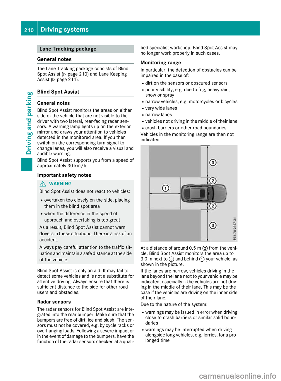
indicated. At a distance of around 0.5 m
;from the vehi-
cle, Blind Spot Assist monitors the area up to
3.0 mnext to =and behind :your vehicle, as
shown in the picture.
If the lanes are narrow, vehicles driving in the
lane beyond the lane next to your vehicle may be
indicated, especially if the vehicles are not driv-
ing in the middle of their lane. This may be the
case if the vehicles are driving on the inner side of their lane.
Due to the nature of the system:
R warnings may be issued in error when driving
close to crash barriers or similar solid boun-
daries
R warnings may be interrupted when driving
alongside long vehicles, e.g. lorries, for a pro-
longed time 210
Driving systemsDriving and parking
Page 214 of 389
Warning lamp
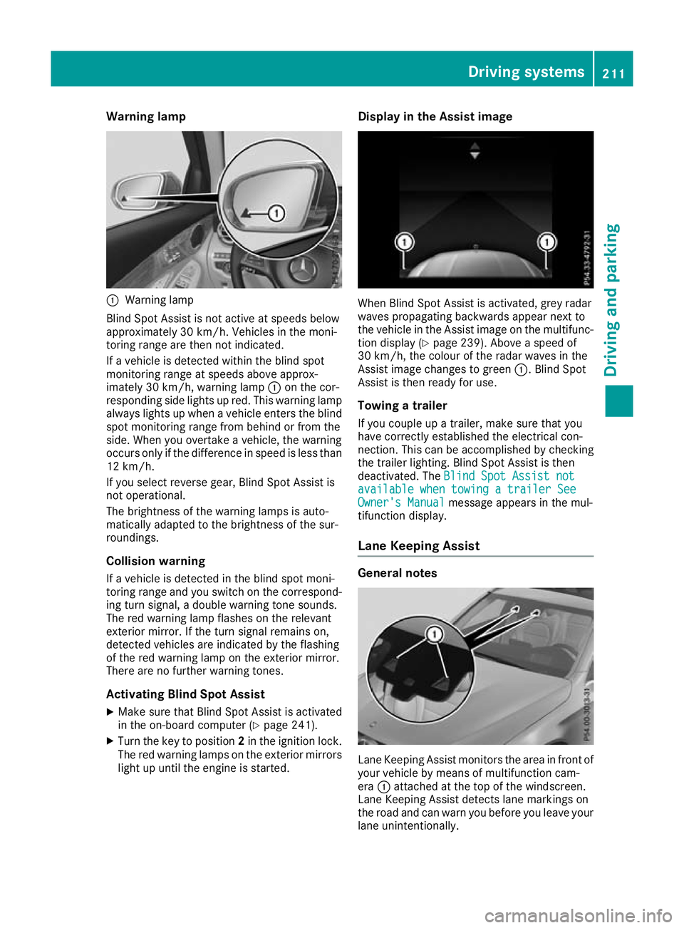
:
Warning lamp
Blind Spot Assist is not active at speeds below
approximately 30 km/h. Vehicles in the moni-
toring range are then not indicated.
If a vehicle is detected within the blind spot
monitoring range at speeds above approx-
imately 30 km/h, warning lamp :on the cor-
responding side lights up red. This warning lamp always lights up when a vehicle enters the blindspot monitoring range from behind or from the
side. When you overtake a vehicle, the warning
occurs only if the difference in speed is less than
12 km/h.
If you select reverse gear, Blind Spot Assist is
not operational.
The brightness of the warning lamps is auto-
matically adapted to the brightness of the sur-
roundings.
Collision warning
If a vehicle is detected in the blind spot moni-
toring range and you switch on the correspond-
ing turn signal, a double warning tone sounds.
The red warning lamp flashes on the relevant
exterior mirror. If the turn signal remains on,
detected vehicles are indicated by the flashing
of the red warning lamp on the exterior mirror.
There are no further warning tones.
Activating Blind Spot Assist
X Make sure that Blind Spot Assist is activated
in the on-board computer (Y page 241).
X Turn the key to position 2in the ignition lock.
The red warning lamps on the exterior mirrors
light up until the engine is started. Display in the Assist image
When Blind Spot Assist is activated, grey radar
waves propagating backwards appear next to
the vehicle in the Assist image on the multifunc-
tion display (Y page 239). Above a speed of
30 km/h, the colour of the radar waves in the
Assist image changes to green :. Blind Spot
Assist is then ready for use.
Towing a trailer
If you couple up a trailer, make sure that you
have correctly established the electrical con-
nection. This can be accomplished by checking
the trailer lighting. Blind Spot Assist is then
deactivated. The Blind Spot Assist not Blind Spot Assist not
available when towing a trailer See
available when towing a trailer See
Owner's Manual Owner's Manual message appears in the mul-
tifunction display.
Lane Keeping Assist General notes
Lane Keeping Assist monitors the area in front of
your vehicle by means of multifunction cam-
era :attached at the top of the windscreen.
Lane Keeping Assist detects lane markings on
the road and can warn you before you leave your lane unintentionally. Driving systems
211Driving and parking Z
Page 216 of 389
R
you have switched on the turn signal. In this
case, the warnings are suppressed for a cer-
tain period of time.
R a driving safety system such as ABS, BAS or
ESP ®
engages
Adaptive
When Adaptive Adaptive is selected, no warning vibra-
tion occurs if:
R you have switched on the turn signal. In this
case, the warnings are suppressed for a cer-
tain period of time.
R a driving safety system such as ABS, BAS or
ESP ®
engages
R you accelerate hard, e.g. kickdown
R you brake hard
R you steer actively, e.g. swerve to avoid an
obstacle or change lane quickly
R you cut the corner on a sharp bend
To ensure that you are warned only when nec-
essary and in good time if you cross the lane
marking, the system detects certain conditions
and warns you accordingly.
The warning vibration occurs earlier in the fol-
lowing situations:
R you approach the outer lane marking on a
bend
R the road has very wide lanes, e.g. a motorway
R the system detects solid lane markings
The warning vibration occurs later in the follow- ing situations:
R the road has narrow lanes
R you cut the corner on a bend Driving Assistance Plus package
General notes The Driving Assistance PLUS package consists
of DISTRONIC PLUS (Y page 178), Active Blind
Spot Assist (Y page 213) and Active Lane Keep-
ing Assist (Y page 216).
Active Blind Spot Assist General notes
Using two lateral, rear-facing radar sensors,
Active Blind Spot Assist monitors the areas on
either side of the vehicle that are not visible to
the driver. A warning lamp lights up on the exte- rior mirrors and draws your attention to vehicles
detected in the monitored area. If you then
switch on the corresponding turn signal to
change lanes, you will also receive a visual and
audible warning. If a risk of side impact is detec- ted, a course-corrective brake application may
help you avoid a collision. Active Blind Spot
Assist evaluates the free space in the direction
of travel and to the side before making a course-correcting brake application. For this, Active
Blind Spot Assist uses the forward-facing radar
sensors.
Active Blind Spot Assist supports you from a
speed of approximately 30 km/h.
Important safety notes Active Blind Spot Assist is only an aid and is not
a substitute for attentive driving. G
WARNING
Active Blind Spot Assist does not react to
vehicles:
R overtaking too closely on the side, placing
them in the blind spot area
R if the difference in the speed of approach
and overtaking is too great
As a result, Active Blind Spot Assist may nei-
ther give warnings nor intervene in such sit-
uations. There is a risk of an accident.
Always pay careful attention to the traffic sit-
uation and maintain a safe distance at the side of the vehicle.
Radar sensors
The Active Blind Spot Assist radar sensors are
integrated in the front and rear bumpers and
behind a cover in the radiator trim. Make sure
that the bumpers and the cover in the radiator
trim are free of dirt, ice or slush. The rear sen-
sors must not be covered, e.g. by bicycle racks
or overhanging loads. Following a severe impact or in the event of damage to the bumpers, have
the function of the radar sensors checked at a
qualified specialist workshop. Active Blind Spot
Assist might otherwise no longer function prop-
erly. Driving systems
213Driving and parking Z
Page 218 of 389
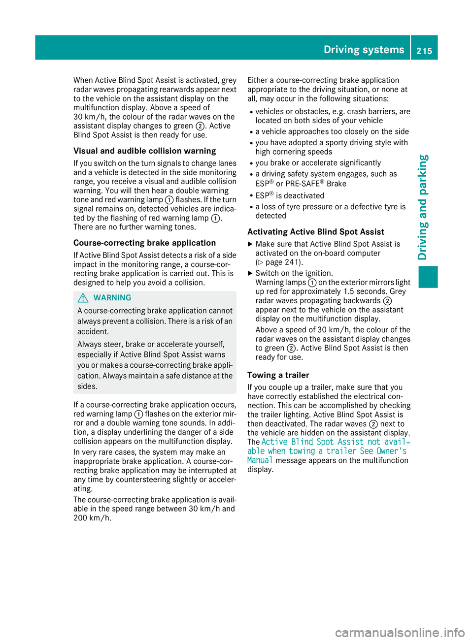
When Active Blind Spot Assist is activated, grey
radar waves propagating rearwards appear next
to the vehicle on the assistant display on the
multifunction display. Above a speed of
30 km/h, the colour of the radar waves on the
assistant display changes to green ;. Active
Blind Spot Assist is then ready for use.
Visual and audible collision warning If you switch on the turn signals to change lanes
and a vehicle is detected in the side monitoring range, you receive a visual and audible collision warning. You will then hear a double warning
tone and red warning lamp :flashes. If the turn
signal remains on, detected vehicles are indica-
ted by the flashing of red warning lamp :.
There are no further warning tones.
Course-correcting brake application
If Active Blind Spot Assist detects a risk of a side
impact in the monitoring range, a course-cor-
recting brake application is carried out. This is
designed to help you avoid a collision. G
WARNING
A course-correcting brake application cannot always prevent a collision. There is a risk of an
accident.
Always steer, brake or accelerate yourself,
especially if Active Blind Spot Assist warns
you or makes a course-correcting brake appli-
cation. Always maintain a safe distance at the sides.
If a course-correcting brake application occurs, red warning lamp :flashes on the exterior mir-
ror and a double warning tone sounds. In addi-
tion, a display underlining the danger of a side
collision appears on the multifunction display.
In very rare cases, the system may make an
inappropriate brake application. A course-cor-
recting brake application may be interrupted at
any time by countersteering slightly or acceler-
ating.
The course-correcting brake application is avail-
able in the speed range between 30 km/h and
200 km/h. Either a course-correcting brake application
appropriate to the driving situation, or none at
all, may occur in the following situations:
R vehicles or obstacles, e.g. crash barriers, are
located on both sides of your vehicle
R a vehicle approaches too closely on the side
R you have adopted a sporty driving style with
high cornering speeds
R you brake or accelerate significantly
R a driving safety system engages, such as
ESP ®
or PRE-SAFE ®
Brake
R ESP ®
is deactivated
R a loss of tyre pressure or a defective tyre is
detected
Activating Active Blind Spot Assist X Make sure that Active Blind Spot Assist is
activated on the on-board computer
(Y page 241).
X Switch on the ignition.
Warning lamps :on the exterior mirrors light
up red for approximately 1.5 second s. Grey
radar waves propagating backwards ;
appear next to the vehicle on the assistant
display on the multifunction display.
Above a speed of 30 km/h, the colour of the
radar waves on the assistant display changes to green ;. Active Blind Spot Assist is then
ready for use.
Towing a trailer
If you couple up a trailer, make sure that you
have correctly established the electrical con-
nection. This can be accomplished by checking
the trailer lighting. Active Blind Spot Assist is
then deactivated. The radar waves ;next to
the vehicle are hidden on the assistant display.
The Active Active Blind
BlindSpot
Spot Assist
Assist not
notavail‐
avail‐
able
able when
whentowing
towing a
atrailer
trailer See
SeeOwner's
Owner's
Manual
Manual message appears on the multifunction
display. Driving systems
215Driving and parking Z
Page 320 of 389
Sun visors
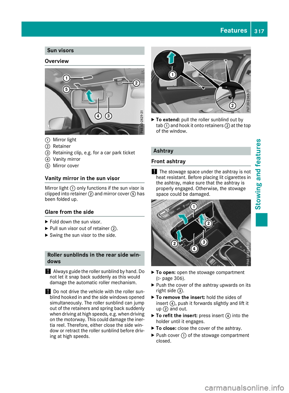
Overview :
Mirror light
; Retainer
= Retaining clip, e.g. for a car park ticket
? Vanity mirror
A Mirror cover
Vanity mirror in the sun visor Mirror light
:only functions if the sun visor is
clipped into retainer ;and mirror cover Ahas
been folded up.
Glare from the side X
Fold down the sun visor.
X Pull sun visor out of retainer ;.
X Swing the sun visor to the side. Roller sunblinds in the rear side win-
dows
! Always guide the roller sunblind by hand. Do
not let it snap back suddenly as this would
damage the automatic roller mechanism.
! Do not drive the vehicle with the roller sun-
blind hooked in and the side windows opened simultaneously. The roller sunblind can jump
out of the retainers and spring back suddenly
when driving at high speeds, e.g. when driving on the motorway. This could damage the iner-
tia reel. Therefore, either close the side win-
dow or retract the roller sunblind before driv- ing at high speeds. X
To extend: pull the roller sunblind out by
tab :and hook it onto retainers ;at the top
of the window. Ashtray
Front ashtray !
The stowage space under the ashtray is not
heat resistant. Before placing lit cigarettes in the ashtray, make sure that the ashtray is
properly engaged. Otherwise, the stowage
space could be damaged. X
To open: open the stowage compartment
(Y page 306).
X Push the cover of the ashtray upwards on its
right side =.
X To remove the insert: hold the sides of
insert ?, push it forwards slightly and lift it
up ; and out.
X To refit the insert: press insert?into the
holder until it engages.
X To close: close the cover of the ashtray.
X Push cover :of the stowage compartment
closed. Features
317Stowing and features Z
Page 338 of 389
Cleaning the mirror turn signal
!
Only use cleaning agents or cleaning cloths
that are suitable for plastic lenses. Unsuitable
cleaning agents or cleaning cloths could
scratch or damage the plastic lenses of the
mirror turn signals.
X Clean the plastic lenses of the mirror turn sig-
nals in the exterior mirror housing using a wet sponge and mild cleaning agent, e.g.
Mercedes-Benz car shampoo or cleaning
cloths.
Cleaning the side running board !
Do not clean the aluminium inserts of the
side running board with alkaline or acidic
cleaners, such as wheel cleaner. Do not use
acidic wheel cleaners to remove brake dust.
The aluminium inserts could otherwise be
damaged.
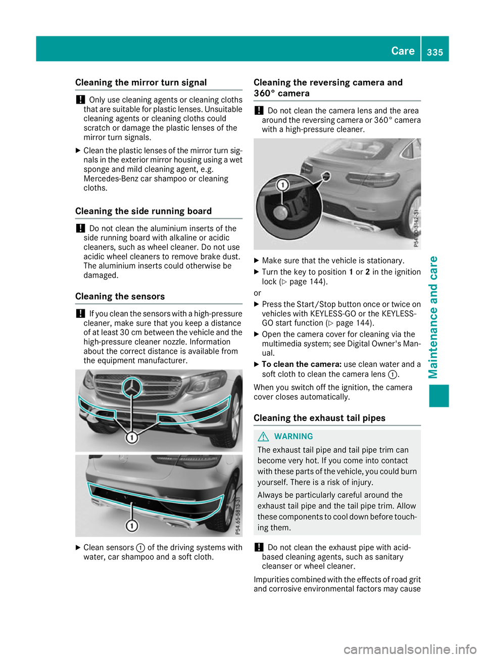
Cleaning the sensors !
If you clean the sensors with a high-pressure
cleaner, make sure that you keep a distance
of at least 30 cm between the vehicle and the
high-pressure cleaner nozzle. Information
about the correct distance is available from
the equipment manufacturer. X
Clean sensors :of the driving systems with
water, car shampoo and a soft cloth. Cleaning the reversing camera and
360° camera !
Do not clean the camera lens and the area
around the reversing camera or 360° camera
with a high-pressure cleaner. X
Make sure that the vehicle is stationary.
X Turn the key to position 1or 2in the ignition
lock (Y page 144).
or X Press the Start/Stop button once or twice on
vehicles with KEYLESS-GO or the KEYLESS-
GO start function (Y page 144).
X Open the camera cover for cleaning via the
multimedia system; see Digital Owner's Man-
ual.
X To clean the camera: use clean water and a
soft cloth to clean the camera lens :.
When you switch off the ignition, the camera
cover closes automatically.
Cleaning the exhaust tail pipes G
WARNING
The exhaust tail pipe and tail pipe trim can
become very hot. If you come into contact
with these parts of the vehicle, you could burn
yourself. There is a risk of injury.
Always be particularly careful around the
exhaust tail pipe and the tail pipe trim. Allow
these components to cool down before touch-
ing them.
! Do not clean the exhaust pipe with acid-
based cleaning agents, such as sanitary
cleanser or wheel cleaner.
Impurities combined with the effects of road grit and corrosive environmental factors may cause Care
335Maintenance and care Z
Page 382 of 389
Make sure the windscreen washer concen-
trate does not come into contact with the filler neck.
! Only use washer fluid that is suitable for
plastic lamp lenses, e.g. MB SummerFit or MB
WinterFit. Unsuitable washer fluid could dam-
age the plastic lenses of the headlamps.
! Only the washer fluids SummerFit and Win-
terFit can be mixed. Otherwise, the spraying
nozzles could become blocked.
Do not use distilled or de-ionised water, other-
wise the level sensor may give a false reading.
When handling washer fluid, observe the impor- tant safety notes on service products
(Y page 373).
At temperatures above freezing:
X Fill the washer fluid reservoir with a mixture of
water and washer fluid, e.g. MB SummerFit.
Mix 1 part MB SummerFit to 100 parts water.
At temperatures below freezing:
X Fill the washer fluid reservoir with a mixture of
water and washer fluid, e.g. MB WinterFit.
For the correct mixing ratio, refer to the infor- mation on the antifreeze reservoir.
i Add washer fluid concentrate, e.g. MB Sum-
merFit or MB WinterFit, to the washer fluid all
year round. Vehicle data
General notes
Please note that for the specified vehicle data:
R the heights specified may vary as a result of:
- tyres
- load
- condition of the suspension
- optional equipment
R items of optional equipment reduce the max-
imum payload
R vehicle-specific weight information can be
found on the vehicle identification plate
(Y page 372)
R for certain countries only: you can find vehi-
cle-specific vehicle data in the COC docu-
ments (CERTIFICATE OF CONFORMITY). These documents are delivered with your
vehicle
Observe the information relating to level con-
trol:
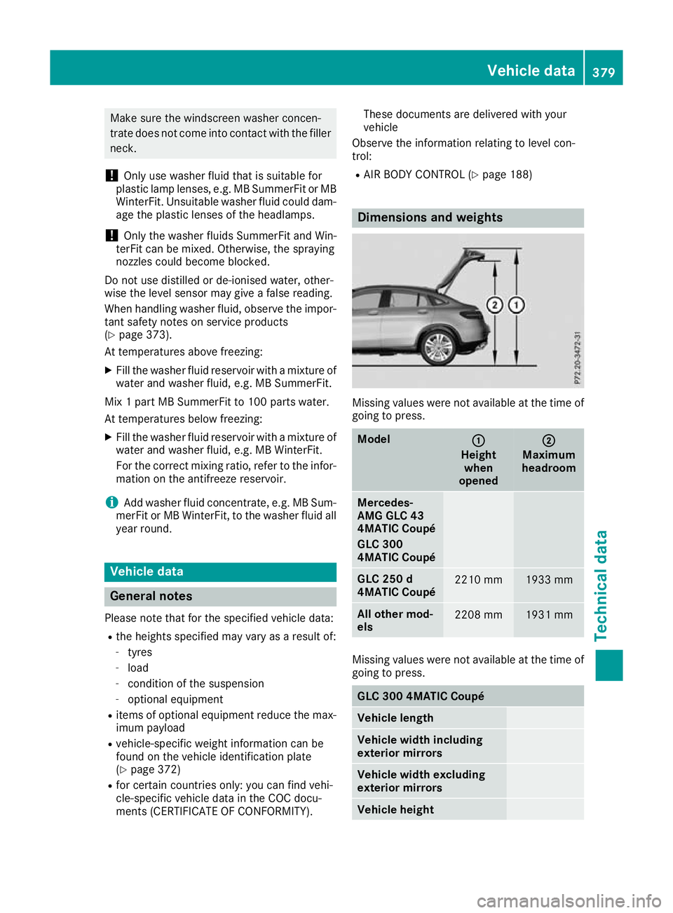
R AIR BODY CONTROL (Y page 188) Dimensions and weights
Missing values were not available at the time of
going to press. Model
: :
Height when
opened ;
;
Maximum
headroom Mercedes-
AMG GLC 43
4MATIC Coupé
GLC 300
4MATIC Coupé
GLC 250 d
4MATIC Coupé
2210 mm 1933 mm
All other mod-
els
2208 mm 1931 mm
Missing values were not available at the time of
going to press. GLC 300 4MATIC Coupé
Vehicle length
Vehicle width including
exterior mirrors
Vehicle width excluding
exterior mirrors
Vehicle height Vehicle data
379Technical data Z
Page 383 of 389
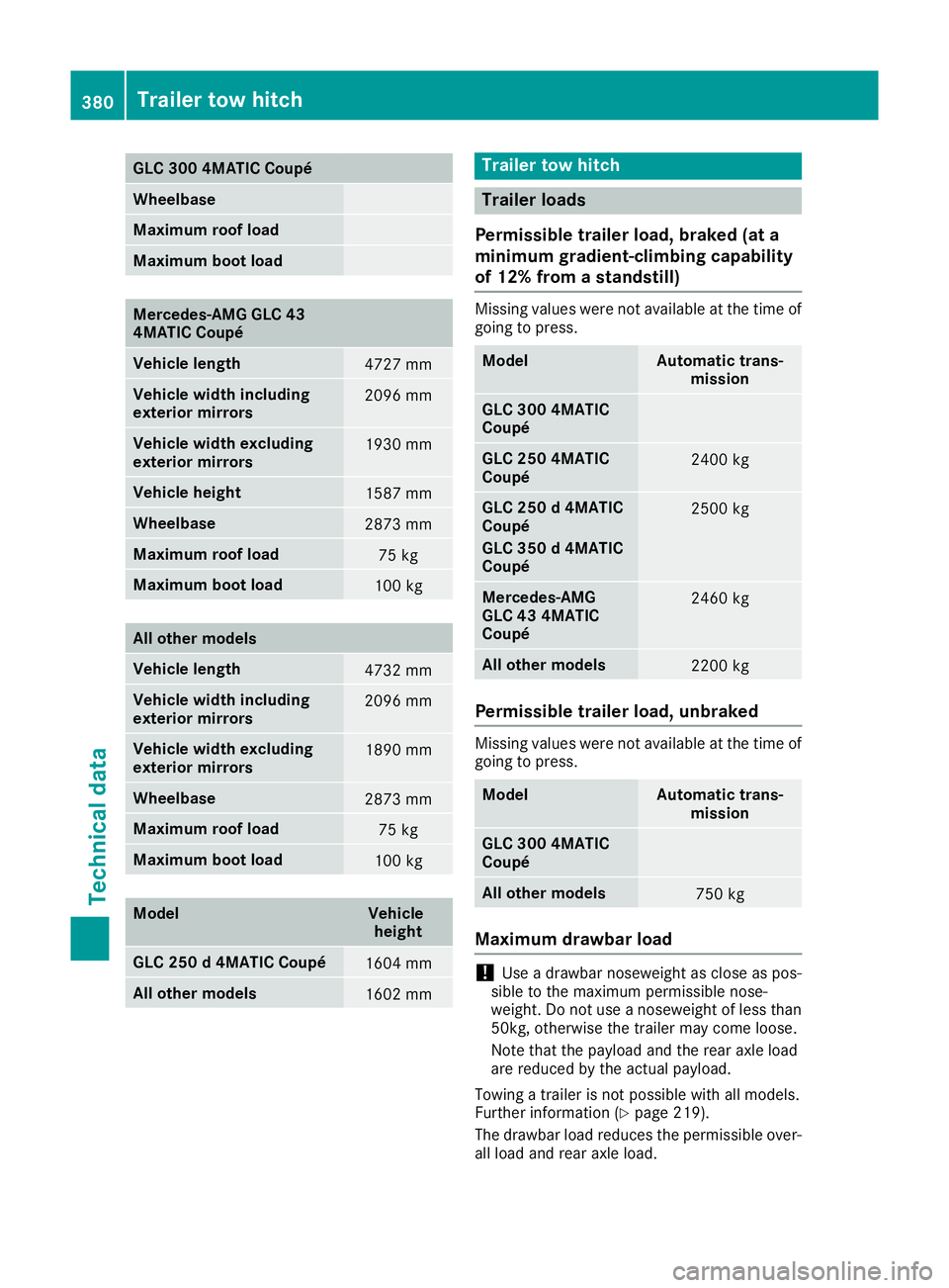
GLC 300 4MATIC Coupé
Wheelbase
Maximum roof load
Maximum boot load
Mercedes-AMG GLC 43
4MATIC Coupé
Vehicle length
4727 mm
Vehicle width including
exterior mirrors
2096 mm
Vehicle width excluding
exterior mirrors
1930 mm
Vehicle height
1587 mm
Wheelbase
2873 mm
Maximum roof load
75 kg
Maximum boot load
100 kg
All other models
Vehicle length
4732 mm
Vehicle width including
exterior mirrors
2096 mm
Vehicle width excluding
exterior mirrors
1890 mm
Wheelbase
2873 mm
Maximum roof load
75 kg
Maximum boot load
100 kg
Model Vehicle
height GLC 250 d 4MATIC Coupé
1604 mm
All other models
1602 mm Trailer tow hitch
Trailer loads
Permissible trailer load, braked (at a
minimum gradient-climbing capability
of 12% from a standstill) Missing values were not available at the time of
going to press. Model Automatic trans-
mission GLC 300 4MATIC
Coupé
GLC 250 4MATIC
Coupé
2400 kg
GLC 250 d 4MATIC
Coupé
GLC 350 d 4MATIC
Coupé
2500 kg
Mercedes-AMG
GLC 43 4MATIC
Coupé
2460 kg
All other models
2200 kg
Permissible trailer load, unbraked
Missing values were not available at the time of
going to press. Model Automatic trans-
mission GLC 300 4MATIC
Coupé
All other models
750 kg
Maximum drawbar load
!
Use a drawbar noseweight as close as pos-
sible to the maximum permissible nose-
weight. Do not use a noseweight of less than
50kg, otherwise the trailer may come loose.
Note that the payload and the rear axle load
are reduced by the actual payload.
Towing a trailer is not possible with all models.
Further information (Y page 219).
The drawbar load reduces the permissible over- all load and rear axle load. 380
Trailer tow hitchTechnical data