MERCEDES-BENZ GLC COUPE 2017 X253 Owner's Manual
Manufacturer: MERCEDES-BENZ, Model Year: 2017, Model line: GLC COUPE, Model: MERCEDES-BENZ GLC COUPE 2017 X253Pages: 370, PDF Size: 6.08 MB
Page 201 of 370
which the maximum permissible speed for vehi-
cle/trailer combinations is above 60 mph
(100 km/h).
When towing a trailer, your vehicle's handling
characteristics will be different in comparison towhen driving without a trailer and it will con-
sume more fuel.
Shift to a lower gear on long and steep downhill
gradients.
This also applies to:
Ractivated DISTRONIC PLUS
Ractivated cruise control
This will use the braking effect of the engine, so that less braking will be required to maintain the
speed. This relieves the load on the brake sys-
tem and prevents the brakes from overheating
and wearing too quickly. If you need additional
braking, depress the brake pedal repeatedly
rather than continuously.
Driving tips
If the trailer swings from side to side:
XDo not accelerate.
XDo not counter-steer.
XBrake if necessary.
RMaintain a greater distance from the vehicle
in front than when driving without a trailer.
RAvoid braking abruptly. If possible, brake gen-tly at first to allow the trailer to run on. Then,
increase the braking force rapidly.
RThe values given for gradient-climbing capa-
bilities from a standstill refer to sea level.
When driving in mountainous areas, note that
the power output of the engine and, conse-
quently, the vehicle's gradient-climbing capa-
bility, decreases with increasing altitude.
Installing the ball coupling
GWARNING
If the ball coupling is not correctly installed
and secured, it could come loose while driving and endanger other road users. There is a risk
of an accident and injury.
Install and secure the ball coupling as descri-
bed in the ball coupling manufacturer's instal- lation instructions. Make sure that the ball
coupling is correctly installed and secured
before every journey.
GWARNING
If the ball coupling is not installed and secured
correctly the trailer may come loose. There is
a risk of an accident.
Install and secure the ball coupling as descri-
bed in the ball coupling installation instruc-
tions. Make sure that the ball coupling is
installed and secured correctly before every
journey.
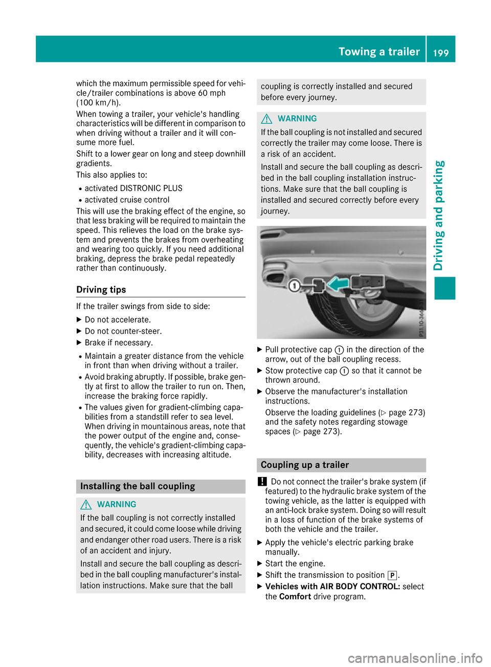
XPull protective cap :in the direction of the
arrow, out of the ball coupling recess.
XStow protective cap :so that it cannot be
thrown around.
XObserve the manufacturer's installation
instructions.
Observe the loading guidelines (
Ypage 273)
and the safety notes regarding stowage
spaces (
Ypage 273).
Coupling up a trailer
!
Do not connect the trailer's brake system (if
featured) to the hydraulic brake system of the
towing vehicle, as the latter is equipped with
an anti-lock brake system. Doing so will result
in a loss of function of the brake systems of
both the vehicle and the trailer.
XApply the vehicle's electric parking brake
manually.
XStart the engine.
XShift the transmission to position j.
XVehicles with AIR BODY CONTROL: select
the Comfort drive program.
Towing a trailer199
Driving and parking
Z
Page 202 of 370
XSwitch off the engine.
XClose the doors and tailgate.
XCouple up the trailer.
XEstablish the electrical connection between
the vehicle and the trailer.
XCheck that the trailer lighting system is work-
ing.
XPush the combination switch upwards/down-wards and check whether the corresponding
turn signal on the trailer flashes.
A trailer that is connected is recognized only
when the electrical connection is established
correctly and when the lighting system is work-
ing properly. The function of other systems also
depends on this, for example:
RESP®
RPARKTRONIC
RActive Parking Assist
RActive Blind Spot Assist
RActive Lane Keeping Assist
Vehicles with AIR BODY CONTROL: if you couple
up a trailer, the vehicle always remains at high-
way level. Observe the following note when cou-
pling up a trailer:
RUnless highway level has been set manually,
the vehicle is automatically lowered to high-
way level. If a speed of 5 mph (8 km/h) has
been reached, this may be the case.
These restrictions apply to accessories that are
supplied with power via the trailer socket in your
vehicle, e.g. a rear bicycle rack.
Observe the maximum permissible trailer
dimensions (width and length).
Most U.S. states and all Canadian provinces
require by law:
RSafety chains between the towing vehicle and
the trailer. The chains should be cross-wound
under the trailer drawbar. They must be fas-
tened to the vehicle's trailer coupling, not to
the bumper or the axle.
Leave enough play in the chains to make tight
cornering possible.
RA separate brake system for certain types of
trailer.
RSafety switch for braked trailers. Check the
specific legal requirements applicable to your state.
If the trailer becomes detached from the tow-
ing vehicle, the safety feature applies the
trailer brakes.
Towing a trailer
There are several legal requirements for towing
a trailer, e.g. the maximum permissible speed.
Make sure that your car/trailer combination
complies with the local regulations:
Rin your place of residence
Rat your destination
The police and local authorities can provide reli- able information.
To accumulate driving experience and accustom
yourself to the new handling characteristics,
practice the following at a location where there
is no traffic:
RCornering
RStopping
RBacking up
Check the following before the journey:
RTrailer tow hitch
RSafety switch for braked trailers
RSafety chains
RElectrical connections
RLighting system
RWheels and tires
RLoad securing
Adjust the exterior mirrors so that you have a
clear view of the rear section of the trailer.
If the trailer is equipped with electronically con-
trolled brakes, pull away carefully in the car/
trailer combination. Brake manually using the
brake controller and check whether the brakes
function correctly.
Regularly check that the load is secure.
When towing a trailer, your vehicle's handling
characteristics will be different in comparison
with when driving without a trailer.
The vehicle/trailer combination:
Ris heavier
Ris restricted in its acceleration and gradient-
climbing capability
Rhas an increased braking distance
Ris affected more by strong crosswinds
Rdemands more sensitive steering
Rhas a larger turning circle
Avoid sudden steering movements.
Avoid braking abruptly. If possible, brake gently
at first to allow the trailer to run on. Then,
increase the braking force rapidly.
200Towing a trailer
Driving and parking
Page 203 of 370
When overtaking, pay particular attention to the
extended length of your vehicle/trailer combi-
nation.
Due to the length of the vehicle/trailer combi-
nation, you require additional road space when
overtaking before you can change back to the
original lane.
If the automatic transmission repeatedly shifts
between gears on uphill or downhill gradients,
shift to a lower gear.
Driving in a lower gear and at a reduced speed
decreases the risk of engine damage.
If the coolant temperature increases signifi-
cantly when climate control is switched on,
switch climate control off.
Coolant heat can also be dissipated by opening
the windows and switching the ventilation
blower and the interior temperature to the high-
est level.
Decoupling a trailer
GWARNING
If you uncouple a trailer with the overrun
brake engaged, you could trap your hand
between the vehicle and the trailer drawbar.
There is a risk of injury.
Do not uncouple a trailer if the overrun brake
is engaged.
GWARNING
Vehicles with level control:
The vehicle is lowered as soon as you discon-
nect the trailer cable. This could result in your
limbs or those of other people that are
between the vehicle body and tires or under-
neath the vehicle being trapped. There is a
risk of injury.
Make sure that nobody is in the immediate
vicinity of the wheel housings or under the
vehicle when you disconnect the trailer cable.
!Do not disconnect a trailer with an engaged
overrun brake. Otherwise, your vehicle could
be damaged by the rebounding of the overrun
brake.
XApply the vehicle's parking brake manually.
XShift the transmission to position j.
XClose all doors and the tailgate.
XSwitch off the engine.
XSecure the vehicle and trailer against rolling
away.
XRemove the trailer cable.
XRemove the safety chains, if there are any.
XUncouple the trailer.
Removing the ball coupling
XObserve the manufacturer's installation
instructions.
XPress the protective cap into the ball coupling
recess.
XMake sure that the protective cap is firmly in
place.
Observe the loading guidelines (
Ypage 273)
and the safety notes regarding stowage spaces
(
Ypage 273).
Information on cleaning and care of the trailer
tow hitch (
Ypage 310).
Trailer power supply
!
Accessories with a maximum power con-
sumption of 180 W can be connected to the
permanent power supply.
You must not charge a trailer battery using the
power supply.
The trailer socket of your vehicle is equipped at
the factory with a permanent power supply.
The permanent power supply is supplied via
trailer socket pin 4.
The trailer's permanent power supply is
switched off in the event of low vehicle supply
voltage and after six hours at the latest.
A qualified specialist workshop can provide
more information about installing the trailer
electrics.
Permissible trailer loads and trailer
drawbar noseweights
Weight specifications
The gross trailer weight is calculated as the
weight of the trailer plus the weight of the load
and the trailer's equipment.
Towing a trailer201
Driving and parking
Z
Page 204 of 370
You will find permissible trailer loads under
"Technical data" (Ypage 365).
Loading a trailer
RWhen loading the trailer, make sure that nei-
ther the permissible gross trailer weight nor
the permissible gross vehicle weight are
exceeded. The permissible gross vehicle
weight is indicated on the identification plate
on the B-pillar on the driver's side of the vehi-
cle.
You can find the maximum permissible valueson the type plates of your vehicle and the
trailer. When calculating how much weight
the vehicle and trailer may carry, pay atten-
tion to the respective lowest values.
RThe trailer drawbar load on the ball coupling
must be added to the rear axle load to avoid
exceeding the permissible gross axle weight.
The permissible gross vehicle weight is indi-
cated on the identification plate on the B-pil-
lar on the driver's side of the vehicle.
Mercedes-Benz recommends a trailer load
where the trailer drawbar noseweight accounts
for 8% to 15% of the permissible gross trailer
weight.
Additional accessories, passengers and load
reduce the permissible trailer load and nose-
weight that your vehicle can tow.
Checking the vehicle and trailer weight
RHave the towing vehicle, including the driver,
passengers and load, and completely loaded
trailer weighed on a suitable weighing
machine. This will allow you to ensure that the
weights of the towing vehicle and trailer com-
ply with the maximum permissible values.
RCheck the gross axle weight rating of the front
and rear axles, the gross weight of the trailer
and trailer drawbar load.
202Towing a trailer
Driving and parking
Page 205 of 370
Important safety notes
GWARNING
If you operate information systems and com-
munication equipmen tintegrate din th evehi-
cle while driving ,you will be distracte dfrom
traffic conditions. You could also lose control
of th evehicle. Ther eis aris kof an accident.
Only operate th eequipmen twhen th etraffic
situation permits. If you are no tsur ethat this
is possible ,park th evehicl epayin gattention
to traffic condition sand operate th eequip-
men twhen th evehicl eis stationary.
You must observ eth elegal requirements for th e
country in whic hyou are currentl ydriving when
operating th eon-board computer.
GWARNIN G
If th einstrumen tcluste rhas faile dor mal-
functioned, you may no trecognize function
restriction sin systems relevan tto safety. The
operating safet yof your vehicl emay be
impaired .Ther eis aris kof an accident.
Drive on carefully. Hav eth evehicl echecke d
at aqualified specialist workshop immedi-
ately.
If th eoperating safet yof your vehicl eis
impaired ,pull ove ras soo nas it is saf eto do so.
Contac t aqualified specialist workshop.
The on-board computer only shows message sor
warning sfrom certain systems in th emultifunc-
tion display. You should therefor emak esur e
your vehicl eis operating safely at all times .
Fo ran overview, see th einstrumen tpanel illus-
tration (
Ypage 35).
Displays and operation
Instrument cluster lighting
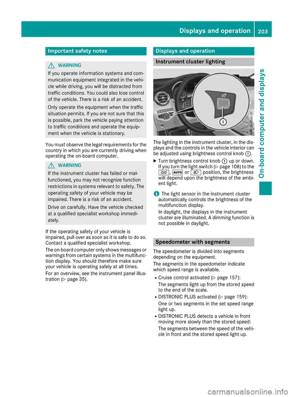
The lighting in th einstrumen tcluster, in th edis-
plays and th econtrol sin th evehicl einterior can
be adjusted usin gbrightness control knob :.
XTurn brightness control knob :up or down .
If you tur nth eligh tswitch (Ypage 108) to th e
T, ÃorL position ,th ebrightness
will depend upon th ebrightness of th eambi -
en tlight.
iThe ligh tsensor in th einstrumen tcluste r
automatically control sth ebrightness of th e
multifunction display.
In daylight, th edisplays in th einstrumen t
cluste rare illuminated. Adimming function is
no tpossibl ein daylight.
Speedometer with segments
The speedometer is divided int osegments
depending on th eequipment.
The segments in th espeedometer indicat e
whic hspee drange is available.
RCruis econtrol activated (Ypage 157):
The segments ligh tup from th estore dspee d
to th een dof th escale.
RDISTRONI CPLU Sactivated (Ypage 159):
On eor two segments in th eset spee drange
ligh tup.
RDISTRONI CPLU Sdetects avehicl ein fron t
moving mor eslowly than th estore dspeed:
The segments between th espee dof th evehi-
cle in fron tand th estore dspee dligh tup.
Displays and operation203
On-board computer and displays
Z
Page 206 of 370
Tachometer
!
Do not drive in the overrevving range, as this
could damage the engine.
The red band in the tachometer indicates the
engine's overrevving range.
The fuel supply is interrupted to protect the
engine when the red band is reached.
Outside temperature display
You should pay special attention to road condi-
tions when temperatures are around freezing
point.
Bear in mind that the outside temperature dis-
play indicates the temperature measured and
does not record the road temperature.
The outside temperature display is in the multi-
function display (
Ypage 205).
Changes in the outside temperature are dis-
played after a short delay.
Coolant temperature gauge
GWARNING
Opening the hood when the engine is over-
heated or when there is a fire in the engine
compartment could expose you to hot gases
or other service products. There is a risk of
injury.
Let an overheated engine cool down before
opening the hood. If there is a fire in the
engine compartment, keep the hood closed
and contact the fire department.
!A display message is shown if the coolant
temperature is too high.
If the coolant temperature is over 248 ‡
(120 †), do not continue driving. The engine
will otherwise be damaged.
The coolant temperature gauge is in the lower
section of the tachometer (
Ypage 35).
Under normal operating conditions and with the
specified coolant level, the coolant temperature
may rise to 248 ‡ (120 †).
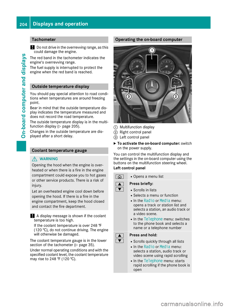
Operating the on-board computer
:Multifunction display
;Right control panel
=Left control panel
XTo activate the on-board computer: switch
on the power supply.
You can control the multifunction display and
the settings in the on-board computer using the
buttons on the multifunction steering wheel.
Left control panel
òROpens a menu list
9
:Press briefly:
RScrolls in lists
RSelects a menu or function
RIn the RadioorMediamenu:
opens a track or station list and
selects a station, an audio track or
a video scene.
RIn the Telephonemenu: switches
to the phone book and selects a
name or a telephone number
9
:Press and hold:
RScrolls quickly through all lists
RIn the RadioorMediamenu:
selects a station, audio track or
video scene using rapid scrolling
RIn the Telephonemenu: starts
rapid scrolling if the phone book is
open
204Displays an doperation
On-boa rd computer and displays
Page 207 of 370
aRIn all menus: confirms the selected
entry in the list
RIn theRadioorMediamenu:
opens the list of available radio
sources or media
RIn the Telephonemenu: switches
to the phone book and starts dial-
ing the selected number
ñRVehicles with multimedia system
Audio 20:
Switches off voice-operated con-
trol for navigation (see the manu-
facturer's operating instructions)
RVehicles with multimedia system
COMAND:
Switches off the Voice Control
System (see the separate operat-
ing instructions)
%Press briefly:
RBack
RIn the RadioorMediamenu: exits
the track or station list or list of
available radio sources or media
RHides display messages
RExits the phone book/redial mem-
ory
%Press and hold:
RCalls up the standard display in the
Tripmenu
Right control panel
~RRejects or ends a call
RExits the phone book/redial mem-
ory
6RMakes or accepts a call
RSwitches to the redial memory
W
XRAdjusts the volume
8RMute
óRVehicles with multimedia system
Audio 20:
Switches on voice-operated con-
trol for navigation (see the manu-
facturer's operating instructions)
RVehicles with multimedia system
COMAND:
Switches on the Voice Control Sys-
tem (see the separate operating
instructions)
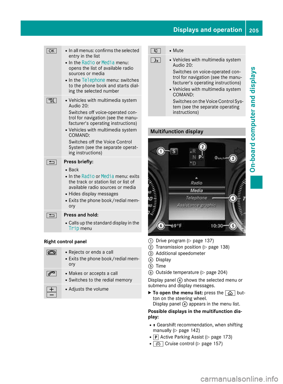
Multifunction display
:Drive program (Ypage 137)
;Transmission position (Ypage 138)
=Additional speedometer
?Display
ATime
BOutside temperature (Ypage 204)
Display panel ?shows the selected menu or
submenu and display messages.
XTo open the menu list: press theòbut-
ton on the steering wheel.
Display panel ?appears in the menu list.
Possible displays in the multifunction dis-
play:
RZ Gearshift recommendation, when shifting
manually (Ypage 142)
Rj Active Parking Assist (Ypage 173)
R¯ Cruise control (Ypage 157)
Displays and operation205
On-board computer and displays
Z
Page 208 of 370
RaDISTRONIC PLUS Steering Assist and
Stop&Go Pilot (Ypage 164)
R_ Adaptive Highbeam Assist
(Ypage 110)
Rè ECO start/stop function (Ypage 131)
RëHOLD function (Ypage 166)
Head-up display
General notes
The head-up display projects information from
the navigation system and the driver assistance
system above the dashboard into the driver's
field of vision. The head-up display allows the
driver to see all of the information without hav-
ing to take their eyes off the road.
A requirement for the display of the contents is that the following functions are available in the
vehicle and are switched on:
RCruise control
RDISTRONIC PLUS
RTraffic Sign Assist
RNavigation
Important safety notes
The head-up display is only an aid and is not a
substitute for attentive driving.
The visibility of the head-up display is influencedby the following conditions:
Rthe driver's seat position
Rthe positioning of the display image
Rthe general ambient light
Rsunglasses with polarization filters
Rwet roads
Rblocking of sunlight by objects on the display
cover
In the event of extreme sunlight, sections of the
display may fade. This can be reversed by
switching the head-up display off and on again.
iVehicles with the head-up display are equip-
ped with a special windshield. Should repairs
be necessary, have the windshield replaced at
a qualified specialist workshop.
Displays and operation
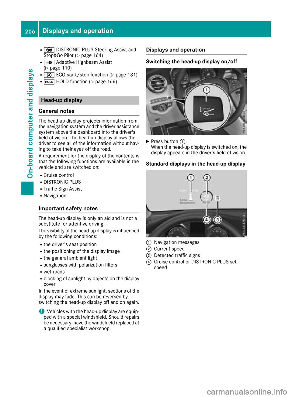
Switching the head-up display on/off
XPress button :.
When the head-up display is switched on, the display appears in the driver's field of vision.
Standard displays in the head-up display
:Navigation messages
;Current speed
=Detected traffic signs
?Cruise control or DISTRONIC PLUS set
speed
206Displays an doperation
On-boa rd computer and displays
Page 209 of 370
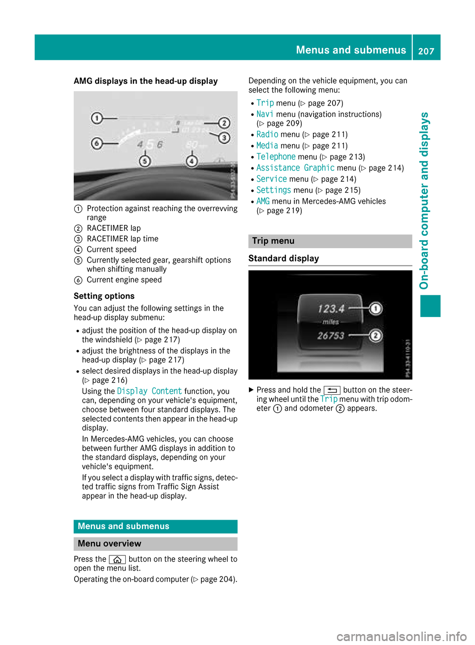
AMG displays inthe head-up display
:Protection against reachin gth eoverrevving
range
;RACETIMER lap
=RACETIMER lap tim e
?Currentspee d
ACurrently selected gear ,gearshif toption s
when shiftin gmanually
BCurren tengin espee d
Setting options
You can adjust th efollowin gsettings in th e
head-up display submenu:
Radjust th epositio nof th ehead-up display on
th ewindshield (Ypage 217)
Radjust thebrightness of th edisplays in th e
head-up display (Ypage 217)
Rselect desired displays in th ehead-up display
(Ypage 216)
Usin gth eDispla yConten t
function ,you
can ,depending on your vehicle's equipment,
choos ebetween four standard displays. The
selected contents then appear in th ehead-up
display.
In Mercedes-AM Gvehicles, you can choos e
between further AM Gdisplays in addition to
th estandard displays, depending on your
vehicle's equipment.
If you select adisplay wit htraffic signs, detec-
te dtraffic sign sfrom Traffic Sig nAssist
appear in th ehead-up display.
Menus and submenus
Menu overview
Press th eò buttonon th esteering whee lto
open th emen ulist .
Operating th eon-board computer (
Ypage 204).Dependin
gon th evehicl eequipment, you can
select th efollowin gmenu:
RTri pmen u (Ypage 207)
RNavimen u(navigation instructions)
(Ypage 209)
RRadiomen u (Ypage 211)
RMediamenu (Ypage 211)
RTelephonemenu (Ypage 213)
RAssistanc eGraphi cmenu (Ypage 214)
RServic emenu (Ypage 214)
RSettingsmenu (Ypage 215)
RAMGmenuin Mercedes-AM Gvehicles
(Ypage 219)
Trip menu
Standard display
XPress and hold th e% buttonon th esteer -
ing whee luntil th eTri pmen uwit htrip odom -
eter :and odometer ;appears.
Menus and submenus207
On-board computer and displays
Z
Page 210 of 370
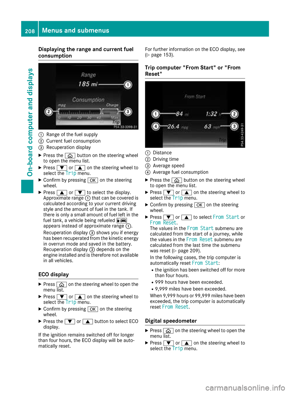
Displaying therange an dcurrent fuel
consumption
:Range of th efue lsupply
;Curren tfue lconsumption
=Recuperation display
XPress th eò buttonon th esteerin gwhee l
to ope nth emen ulist .
XPress :or9 on thesteerin gwhee lto
selec tth eTri pmenu.
XConfir mby pressing aon thesteerin g
wheel.
XPress 9or: to selec tth edisplay.
Approximat erange :that can be covered is
calculated accordin gto your curren tdrivin g
style and th eamount of fue lin th etank .If
there is only asmall amount of fue llef tin th e
fue ltank , avehicle bein grefuele dC
appears instead of approximat erange :.
Recuperation display =shows you if energ y
has bee nrecuperated from th ekineti cenerg y
in overrun mode and saved in th ebattery.
Recuperation display =depend son th e
engin einstalled and is therefore no tavailable
in all vehicles .
ECO display
XPressòon thesteerin gwhee lto ope nth e
men ulist .
XPress :or9 on thesteerin gwhee lto
selec tth eTri pmenu.
XConfir mby pressing aon thesteerin g
wheel.
XPress th e: or9 buttonto selec tEC O
display.
If th eignition remain sswitched of ffo rlonger
than four hours, th eEC Odisplay will be auto-
matically reset . Fo
rfurther information on th eEC Odisplay, see
(
Ypage 153).
Trip compute r"From Start" or "From
Reset "
:Distanc e
;Driving time
=Average speed
?Average fue lconsumption
XPress th eò buttonon th esteerin gwhee l
to ope nth emen ulist .
XPress :or9 on thesteerin gwhee lto
selec tth eTri pmenu.
XConfir mby pressing aon thesteerin g
wheel.
XPress :or9 to selec tFro mStartor
Fro mReset.
The values in th eFro mStartsubmen uare
calculated from th estart of ajourney, whil e
th evalues in th eFro mReset
submen uare
calculated from th elast time th esubmen u
was reset (
Ypage 209).
In th efollowin gcases, th etrip compute ris
automatically reset FromStart
:
Rtheignition has bee nswitched of ffo rmore
than four hours.
R99 9hour shav ebee nexceeded.
R9,999 miles hav ebee nexceeded.
Whe n9,999 hour sor 99,99 9miles hav ebee n
exceeded, th etrip compute ris automatically
reset FromReset
.
Digital speedometer
XPress òon thesteerin gwhee lto ope nth e
men ulist .
XPress :or9 on thesteerin gwhee lto
selec tth eTri pmenu.
208Menus and submenus
On-board computer and displays