battery location MERCEDES-BENZ GLC SUV 2015 Owners Manual
[x] Cancel search | Manufacturer: MERCEDES-BENZ, Model Year: 2015, Model line: GLC SUV, Model: MERCEDES-BENZ GLC SUV 2015Pages: 497, PDF Size: 15.27 MB
Page 15 of 497

Front-passenger front airbag deac-
tivation
Display message ............................ 349
Front-passenger front airbag deac-
tivation system
Operation ........................................ .57
Problems ......................................... 61
System self-test ...............................59
Fuel
Additives ........................................ 483
Consumption information .............. 484
Consumption statistics .................. 319
Displaying the current consump-
tion ................................................ 318
Displaying the range ...................... 318
Driving tips .................................... 222
E10 ................................................ 482
Fuel gauge ...................................... .34
Grade (petrol) ................................ 482
Important safety notes .................. 481
Low outside temperatures ............ .483
Problem (malfunction) ................... 206
Quality (diesel )............................... 483
Refuelling ....................................... 203
Tank content/reserve fue l............. 482
Fuel filler flap
Opening ......................................... 205
Fuel filter (white display message) .. 356
Fuel level
Calling up the range (on-board
computer) ...................................... 318
Gaug e.............................................. 34
Fuel tank
Capacity ........................................ 482
Problem (malfunction) ................... 206
Fuses
Allocation chart ............................. 451
Before changing ............................. 449
Dashboard fuse box ....................... 449
Fuse box in the engine compart-
ment .............................................. 450
Fuse box in the front-passenger
footwell .......................................... 449
Fuse box in the luggage compart-
ment .............................................. 451
Important safety notes .................. 448 G
Gearshift paddles see Steering wheel gearshift paddles
Genuine Mercedes-Benz parts ........... 25
Glove compartment .......................... 391 H
HANDS-FREE ACCESS ....................... 106
Hazard warning lamps ...................... 141
Head restraint
General notes ................................ 124
Head restraints
Adjusting (electrically) ................... 124
Adjusting (manually) ...................... 124
Adjusting (rear) .............................. 125
Adjusting the fore-and-aft posi-
tion manually ................................. 124
Fitting/removing (rear) .................. 125
Important safety notes .................. 123
Head-up display
Adjusting the brightness ................ 331
Displays and operating .................. 316
Function/note s............................. 315
Important safety notes .................. 316
Selecting displays .......................... 330
Setting the position ....................... 331
Storing settings (memory func-
tion) ............................................... 135
Headlamp
Cleaning system (notes) ................ 487
Headlamp flasher .............................. 141
Headlamps
Misting up ...................................... 144
see Automatic headlamp mode
Heating
see Climate control
High-pressure cleaners .................... 422
High-voltage battery
Battery car e................................... 212
Charging (charging station) ............ 217
Charging (mains socket) ................ 213
Charging (wallbox) ......................... 216
Charging cable heating up ............. 212
Energy consumption ...................... 212
General notes .................................. 45
Method of operation ...................... 211 12
Index
Page 16 of 497

Outside temperatures .................... 211
Problems during charging .............. 218
Protective device ........................... 212
Range ............................................ 212
Terms of use ..................................2 12
Vehicle fire ....................................... 45
Hill start assist .................................. 191
HOLD function
Activating ....................................... 248
Activation conditions ..................... 247
Deactivating ................................... 248
Display message ............................ 363
Function/notes ............................ .247
General notes ................................ 247
Horn ...................................................... 32
HUD
see Head-up display
Hybrid drive system
Automatic switch off ........................ 44
Danger of electric shock .................. 44
Display message ............................ 357
General notes .................................. 44
High-voltage battery ........................ 45
Important safety notes .................... 44
Manual switch off ............................ 44
Opening the bonnet ......................... 46
Warning lamp ................................. 377
Hybrid vehicles
Important safety notes .................... 44 I
Ignition lock see Key positions
Immobiliser .......................................... 90
Indicator and warning lamp
Restraint system ............................ 383
Indicator and warning lamps
COLLISION PREVENTION ASSIST
PLUS .............................................. 386
Coolant .......................................... 384
Engine diagnostics ......................... 384
Indicator lamps
Display message ............................ 351
see Warning and indicator lamps
Insect protection on the radiator .... 416
Instrument cluster
Overview .......................................... 34 Warning and indicator lamps ........... 36
Instrument cluster lighting .............. 312
Intelligent Light System
Activating/deactivating ................. 331
Display message ............................ 352
Overview ........................................ 141
Setting the dipped-beam head-
lamps for driving on the right/left .. 332
Interior lighting
Control .......................................... .145
Emergency lighting ........................ 146
Overview ........................................ 145
Reading lamp ................................. 145
Interior motion sensor
Deactivating ..................................... 92
Function .......................................... .91
Priming ............................................ 91
Switching off .................................... 92
ISOFIX child seat securing system ....67 J
Jack Storage location ............................4 32
Using ............................................. 465
Jump starting (engine) ......................443 K
Key Changing the battery ....................... 98
Checking the battery ....................... 98
Convenience closing feature .......... 112
Convenience opening feature ....... .111
Display message ............................ 374
Door central locking/unlocking ....... 95
Emergency key element ................... 97
Important safety notes .................... 94
KEYLESS-GO start function .............. 96
Loss ................................................. 99
Modifying the programming ............. 96
Overview .......................................... 94
Positions (ignition lock) ................. 187
Problem (malfunction) ..................... 99
Starting the engine ........................ 189
Key positions
Key ................................................ 187
Start/Stop button .......................... 187 Index
13
Page 184 of 497

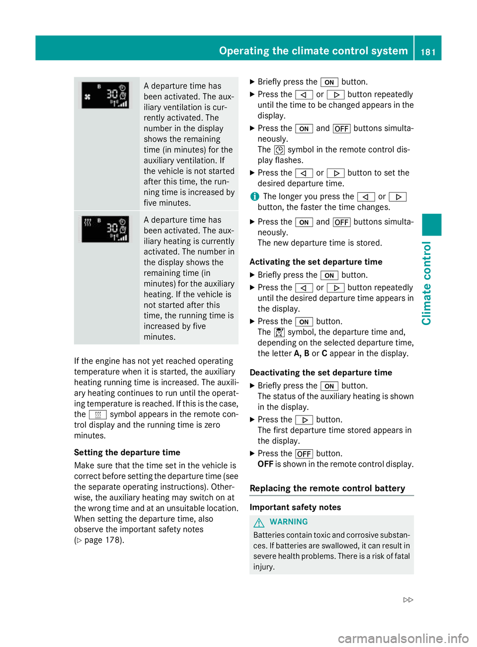
A departure time has
been activated. The aux-
iliary ventilation is cur-
rently activated. The
number in the display
shows the remaining
time (in minutes) for the
auxiliary ventilation. If
the vehicle is not started
after this time, the run-
ning time is increased by
five minutes. A departure time has
been activated. The aux-
iliary heating is currently
activated. The number in
the display shows the
remaining time (in
minutes) for the auxiliary heating. If the vehicle is
not started after this
time, the running time is
increased by five
minutes. If the engine has not yet reached operating
temperature when it is started, the auxiliary
heating running time is increased. The auxili-
ary heating continues to run until the operat- ing temperature is reached. If this is the case,
the y symbol appears in the remote con-
trol display and the running time is zero
minutes.
Setting the departure time
Make sure that the time set in the vehicle is
correct before setting the departure time (see the separate operating instructions). Other-
wise, the auxiliary heating may switch on at
the wrong time and at an unsuitable location.
When setting the departure time, also
observe the important safety notes
(Y page 178). X
Briefly press the ubutton.
X Press the ,or. button repeatedly
until the time to be changed appears in the display.
X Press the uand^ buttons simulta-
neously.
The Îsymbol in the remote control dis-
play flashes.
X Press the ,or. button to set the
desired departure time.
i The longer you press the
,or.
button, the faster the time changes.
X Press the uand^ buttons simulta-
neously.
The new departure time is stored.
Activating the set departure time X Briefly press the ubutton.
X Press the ,or. button repeatedly
until the desired departure time appears in the display.
X Press the ubutton.
The Ísymbol, the departure time and,
depending on the selected departure time, the letter A, BorCappear in the display.
Deactivating the set departure time
X Briefly press the ubutton.
The status of the auxiliary heating is shown in the display.
X Press the .button.
The first departure time stored appears in
the display.
X Press the ^button.
OFF is shown in the remote control display.
Replacing the remote control battery Important safety notes
G
WARNING
Batteries contain toxic and corrosive substan- ces. If batteries are swallowed, it can result in
severe health problems. There is a risk of fatal injury. Operating the climate control system
181Climate control
Z
Page 217 of 497

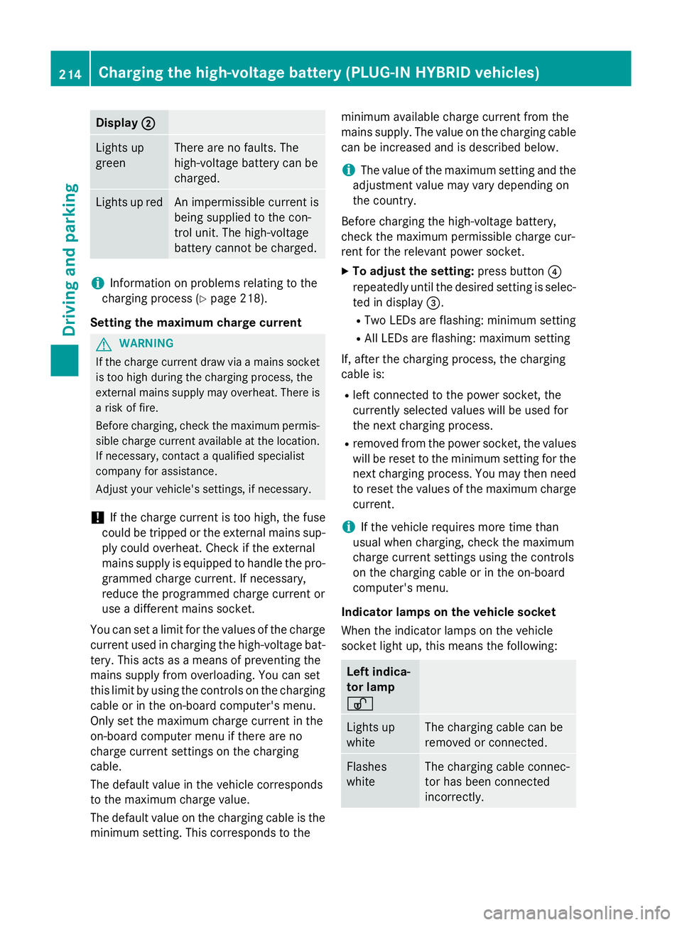
Display
;
; Lights up
green There are no faults. The
high-voltage battery can be
charged.
Lights up red An impermissible current is
being supplied to the con-
trol unit. The high-voltage
battery cannot be charged.
i
Information on problems relating to the
charging process (Y page 218).
Setting the maximum charge current G
WARNING
If the charge current draw via a mains socket is too high during the charging process, the
external mains supply may overheat. There is a risk of fire.
Before charging, check the maximum permis-
sible charge current available at the location.
If necessary, contact a qualified specialist
company for assistance.
Adjust your vehicle's settings, if necessary.
! If the charge current is too high, the fuse
could be tripped or the external mains sup-
ply could overheat. Check if the external
mains supply is equipped to handle the pro- grammed charge current. If necessary,
reduce the programmed charge current or
use a different mains socket.
You can set a limit for the values of the charge
current used in charging the high-voltage bat- tery. This acts as a means of preventing the
mains supply from overloading. You can set
this limit by using the controls on the charging
cable or in the on-board computer's menu.
Only set the maximum charge current in the
on-board computer menu if there are no
charge current settings on the charging
cable.
The default value in the vehicle corresponds
to the maximum charge value.
The default value on the charging cable is the
minimum setting. This corresponds to the minimum available charge current from the
mains supply. The value on the charging cable
can be increased and is described below.
i The value of the maximum setting and the
adjustment value may vary depending on
the country.
Before charging the high-voltage battery,
check the maximum permissible charge cur-
rent for the relevant power socket.
X To adjust the setting: press button?
repeatedly until the desired setting is selec- ted in display =.
R Two LEDs are flashing: minimum setting
R All LEDs are flashing: maximum setting
If, after the charging process, the charging
cable is:
R left connected to the power socket, the
currently selected values will be used for
the next charging process.
R removed from the power socket, the values
will be reset to the minimum setting for the next charging process. You may then need
to reset the values of the maximum charge current.
i If the vehicle requires more time than
usual when charging, check the maximum
charge current settings using the controls
on the charging cable or in the on-board
computer's menu.
Indicator lamps on the vehicle socket
When the indicator lamps on the vehicle
socket light up, this means the following: Left indica-
tor lamp
Ì Ì
Lights up
white The charging cable can be
removed or connected.
Flashes
white The charging cable connec-
tor has been connected
incorrectly. 214
Cha
rging the high-voltage battery (PLUG-IN HYBRI D vehicles)Driving and parking