jump start MERCEDES-BENZ GLE COUPE 2021 Owners Manual
[x] Cancel search | Manufacturer: MERCEDES-BENZ, Model Year: 2021, Model line: GLE COUPE, Model: MERCEDES-BENZ GLE COUPE 2021Pages: 525, PDF Size: 8.83 MB
Page 362 of 525
Obser
vethis Owner's Manual.
Obser vethefo llowing if you do not intend touse
th eve hicle over an extended pe riod of time:
R Activate standby mode.
R Alternatively: connect the battery toa bat‐
te ry charge r appro vedby Mercedes-Benz or
consult a qualified specialist workshop to
disconnect the batter y. Note
s onstarting assi stance and charging
th e12 V battery Ve
hicles with a lithium-ion battery
When charging the battery and during starting
assis tance, al ways use the jump-s tart connec‐
tion point in the engine compartment. *
NO
TEDama getothe battery from over‐
vo ltage When
charging using a bat tery charge r with‐
out a restriction of the maximum charging
vo ltage, the battery or the on-board electron‐
ics can be damaged. #
Only use battery charge rs with a maxi‐
mum charging voltage of 14.8 V. All
other vehicles
When charging the battery and during starting
assis tance, al ways use the jump-s tart connec‐
tion point in the engine compartment.
* NO
TEDama getothe battery from over‐
vo ltage When
charging using a bat tery charge r with‐
out a restriction of the maximum charging
vo ltage, the battery or the on-board electron‐
ics can be damaged. #
Only use battery charge rs with a maxi‐
mum charging voltage of 14.8 V. &
WARNING Risk ofexplosion from hydro‐
ge nga s igniting
There is a danger of hydrogen gas igniting
when charging the battery if there is a short
circuit or spar ksstart toform. #
Make sure that the positive term inal of
th e connected battery does not come
into conta ct withvehicle parts. #
Never place me tal objects or tools on a
batter y. #
The described order of the battery
clamps must be obser ved when con‐
necting and disconnecting the batter y. #
When giving starting assis tance, al ways
make sure that you on lyconnect bat‐
te ry term inals with identical polarity. #
During starting assis tance, you must
obse rveth e described order for con‐
necting and disconnecting the jump
lead. #
Do not connect or disconnect the bat‐
te ry cla mp s while the engine is running. Breakdown assist
ance359
Page 363 of 525
&
WARNING Risk ofexplosion during
ch arging process and starting assis tance
During thech arging process and starting
assis tance, the battery may release an explo‐
sive gas mixture. #
Avoid fire , naked flames, creating
spar ksand smoking. #
Make sure there is suf ficient ventila‐
tion. #
Do not lean over a batter y. &
WARNING Risk ofexplosion from a fro‐
zen battery
A dischar ged battery may freeze at temp era‐
tures slightly abo veor below freezing point.
During starting assis tance or battery charg‐
ing, bat tery gas can be released. #
Alw ays allow a battery tothaw before
ch arging it or per form ing starting assis‐
ta nce. If
th e indicator/warning lamps in the instrument
clus ter do not light up at low temp eratures, it is
ve ry likely that the dischar ged battery has fro‐
zen. In this case you may neither jump-s tart the
ve hicle nor charge the batter y.
The service life of a battery that has been
th awe d may be dramatically shor tened. The
st arting characteristics may be impaired, espe‐
cially at low temp eratures.
It is recommended that you ha veathaw ed bat‐
te ry checked at a qualified specialist workshop.
Plug-in hybrid: be sure toobser vethe no tes in
th e Supplement. You could otherwise failto rec‐
ognise dangers.
All vehicles
* NO
TEDama gecaused bynumerous or
ex tended attempt sto start the engine Nume
rous or extended attempt sto start the
engine may damage the catalytic con verter
due tonon-combu sted fuel. #
Avoid numerous and extended attem pts
to start the engine. Obser
vethefo llowing points during starting
assis tance and when charging the battery:
R Only use undamaged jump lead/charging
cables with a suf ficient cross-section and
insula tedte rm inal clamps.
R Non- insulated parts of thete rm inal clamps
must not come into con tact with other me tal
parts while the jump lead/charging cable is
connected tothe battery/jump-s tart connec‐
tion point.
R The jump lead/charging cable must not
come into contact wi thany parts which may
mo vewhen the engine is running.
R Alw ays make sure that nei ther you nor the
battery is elect rostatically charge d.
R Keep away from fire and naked flames.
R Do not lean overth e batter y.
Obser vethe additional following points when
ch arging the battery:
R Only use battery charge rs tested and
appr oved for Mercedes-Benz.
R Read the battery charge r's operating instruc‐
tions before charging the batter y. 360
Breakdown assis tance
Page 364 of 525
Obser
vethe additional following points during
st arting assistance:
R Starting assis tance may only be pr ovided
using vehicles, batteries or other jump start
devices with a nominal voltage of 12V.
R The vehicles must not touch.
R Vehicles with a petrol engine: jump-start
th eve hicle only when the engine and exhaust
sy stem are cold. St
arting assi stance and charging the12 V
battery Requ
irements:
R The vehicle is secured with the electric park‐
ing brake.
R Vehicles with automatic transmission: the
transmission is in position 005D.
R The ignition and all electrical consumers are
switched off.
R The bonnet is open. Example: engine compartment
#
Slide co ver1 of positive clamp 2onthe
jump-s tarting connection point in the direc‐
tion of the ar row. #
Connect positive clamp 2onyour vehicle to
th e positive pole of the donor battery using
th e jump lead/charging cable. Alw ays begin with positive clamp
2onyour ow nve hicle
fi rs t. #
During starting assi stance: start the
engine of the donor vehicle and run at idle
speed. #
Connect the negative pole of the donor bat‐
te ry and ear thpoint 3ofyour ow nve hicle
by using the jump lead/charging cable. Begin
with the donor battery firs t. #
During starting assi stance: start the
engine of your ow nve hicle. #
During thech arging process: start the
ch arging process. #
During starting assi stance: letthe engines
ru nfo r se veral minutes. #
During starting assi stance: before discon‐
necting the jump lead, switch on an electrical
consumer in your ow nve hicle, e.g. there ar
wind owheater or lighting.
When thest arting assis tance/charging process
is compl ete, per form thefo llowing steps: Breakdown assis
tance 361
Page 365 of 525
#
First,re mo vethe jump lead/charging cable
from ear thpoint 3and the negative pole of
th e donor batter y,then from positive clamp
2 and the positive pole of the donor bat‐
te ry. Begin ea chtime wi th the conta cts on
yo ur ow nve hicle firs t. #
Afterre moving the jump lead/charging
cable, close co ver1 of positive clamp 2.
Fu rther information can be obtained at a quali‐
fi ed specialist workshop. Re
placing the 12V battery #
Obser vethe no tes on the12 V battery
(/ page 357).
Mercedes-Benz recommends that you ha vethe
12 V battery replaced at a qualified specialist
wo rkshop, e.g. at a Mercedes-Benz Service
Centre. Obser
vethefo llowing no tes if youwa ntto
re place the battery yourself:
R Alw aysre place a faulty bat tery with a battery
which meets the specific vehicle require‐
ments.
The vehicle is equipped with an AGMtech nol‐
ogy battery (Absorbent Glass Mat) or a li th‐
ium-ion batter y.Fu llve hicle functionality is
only guaranteed with an AGM battery or lith‐
ium-ion batter y.Fo r saf etyre asons,
Mercedes-Benz recommends that you on ly
use bat teries which ha vebeen tested and
appr ovedfo ryo ur vehicle byMercedes-Benz.
R Carryove r de tach able parts, such as vent
hoses, elbow fittings or term inal co vers from
th e battery being replaced.
R Make sure that theve nt hose is al ways con‐
nected tothe original opening on the side of
th e batter y.
Fit any existing or supplied cell caps.
Otherwise, gases or battery acid could
escape.
R Make sure that de tach able parts are recon‐
nected in the same way. To
w- starting or towing away Overview of
the permit tedto wing me thods Plug-in
hybrid: be sure toobser vethe no tes in
th e Supplement. You could otherwise failto rec‐
ognise dangers.
* NO
TEDama gefrom auto matic braking If one of
thefo llowing functions is switched
on, theve hicle brakes automatically in cer‐
ta in situations:
R Active Brake Assi st
R Active Dis tance Assi stDISTRONIC
R HOLD function
R Active Parking Assist
To avo id damage totheve hicle, deactivate
th ese sy stems in thefo llowing or similar sit‐
uations: #
During towing #
In a car wash 362
Breakdown assis tance
Page 421 of 525
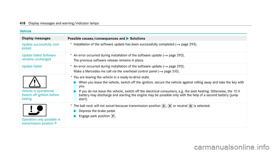
Ve
hicle Display messages
Possible causes/consequences and 0050 0050Solutions
Update successfully com-
pleted *I
nstallation of the software update has been successfully comple ted (/ page 293).
Update failed Software
remains unchanged *A
n er ror occur red during ins tallation of the software update (/ page 293).
The pr evious software release remains in place.
Update failed *A
n er ror occur red during ins tallation of the software update (/ page 293).
Make a Mercedes me call via theove rhead control panel (/ page310).
0072
Vehi cle is operational
Switch off ignition before
exiting *Y
ou are leaving theve hicle in a ready-to-drive state. #
When you lea vetheve hicle, switch off the ignition, secure theve hicle against rolling away and take theke y with
yo u. #
Ifyo u do not lea vetheve hicle, switch off the electrical consumers, e.g. the seat heating. Otherwise, the12 ‑V
battery may discharge and starting the engine may be possible only with the help of a second battery (jump
st art).
ï
Operation only possible in
transmission position P *
The ball neck will not swivel because transmission position 005B,005Eor neut ral005C is selec ted. #
Depress the brake pedal. #
Enga gepark position 005D.41 8
Displaymessa ges and warning/indicator lamps
Page 461 of 525
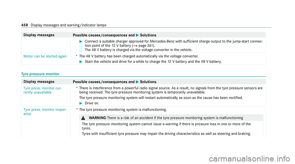
Display messages
Possible causes/consequences and 0050 0050Solutions #
Connect a suitable charge r appro vedfo r Mercedes-Benz with suf ficient charge output tothe jump-s tart connec‐
tion point of the12 V battery (/ page 361).
The 48 V battery is charge d via thevo ltage con verter in theve hicle.
Motor can be started again *T
he 48 V battery has been charge d automatically via thevo ltage con verter. #
Start theve hicle and drive for a while tocharge the12 V battery and the 48 V batter y. Ty
re pressure moni torDisplay messages
Possible causes/consequences and 0050 0050Solutions
Tyre press. monitor cur-
rently unavailable *T
here is inter fere nce from a po werful radio signal source. As a result, no signals from the tyre pressure sensors are
being recei ved. The tyre pressure monitoring sy stem is temp orarily una vailable.
The tyre pressure monitoring sy stem will restart automatically as soon as the cause has been rectified. #
Drive on.
Tyre press. monitor inoper-
ative *T
he tyre pressure monitoring sy stem is malfunctioning. &
WARNING Thereis a risk of an accident if the tyre pressure monitoring sy stem is malfunctioning
The tyre pressure monitoring sy stem cann otissue a warning if there is pressure loss in one or more of the
tyres.
Ty res with insuf ficient tyre pressure may impair the driving characteristics as well as steering and braking. 458
Display messages and warning/indicator lamps
Page 502 of 525
Ad
aptive Highbeam Assist Plus............ .138
Cornering light....................................... 13 6
Fo g light (enhanced)..............................1 37
Mo torw ay mode..................................... 137
Overview............................................... 13 6
Interior lighting Adjusting............................................... 14 0
Ambient lighting..................................... 141
Re ading lam p......................................... 14 0
Switch-off del aytime............................. 14 2
Interior pr otection
Fu nction.................................................. 97
Priming/deactivating.............................. 98
Internet radio
see TuneIn
Ionisation Activating/deactivating (MBUX mul‐
timedia sy stem).....................................1 54
iPhone ®
see Smartphone integ ration
ISOFIX child seat anchor
Seats suitable for attaching..................... 61ISOFIX
child seat securing sy stem
Fitting..................................................... .63 J
Jack Declaration of conformity........................ 30
Storage location.................................... 378
Jump-start connection General no tes........................................ 359 K
Key Acoustic locking verification signal.......... 76
Battery.................................................... 77
Deactivating a function........................... .76
Emergency key........................................ 77
Energy consumption................................ 76
Fu nction overview.................................. .75
Ke yring attachment................................ 77
Problem................................................... 78
Un locking setting.................................... .76
KEYLESS-GO Deactivating a function............................76
Locking/unlocking theve hicle................80 Problem................................................... 80
Un
locking setting.................................... .76
Kickd own
Using.....................................................1 84
Knee airbag .................................................. 45 L
Lamp see In terior lighting
Lamp (instrument display) see Warning/indicator lamp
Lane de tection (au tomatic)
see Active Lane Keeping Assist
Lane Keeping Assist
see Active Lane Keeping Assist
Language Notes....................................................2 96
Setting................................................... 296
LED light see Intelligent Light Sy stem
Le vel control sy stem
see AIRMATIC
see E- ACTIVE BODY CONTROL Index
499
Page 513 of 525
St
arting assi stance
see Jump -star t connection
St arting-o ffaid
see Hill Start Assist
St ationary heater/ventilation
Displ ays (remo tecontrol)...................... 15 8
Problems (remo tecontrol)..................... 15 9
Re placing the battery (remo tecon‐
trol)....................................................... 15 8
Setting (MBUX multimedia sy stem)....... 15 6
Setting (remo tecontrol)........................ 157
Switching on/off (control panel )........... 15 5
ST EER CONT ROL
Fu nction/no tes..................................... 204
Ste ering wheel
Ad justing (electrically)........................... 11 0
Ad justing (manually). ............................. 11 0
Buttons.................................................. 278
Car e...................................................... 347
St eering wheel heater............................ 111
Ste ering wheel gearshift paddles............ 183
Ste ering wheel heater
Swit ching on/of f.................................... 111St
ow age areas
see Loading
see Stow age space
St ow age comp artments
see Loading
see Stow age space
St ow age space
Armrest.................................................. 11 7
Centre console....................................... 11 7
Door....................................................... 11 7
Glo vecompa rtment............................... 11 7
Stre etnames and house numbers
Displaying..............................................3 00
Suggestions Configuri ng........................................... 292
Sulphur content........................................ 395
Sur round lighting
Switching on/of f................................... 14 0
Sur round View
see 360° Camera
Suspension Individual wheel contro l (E-ACTIVE
BO DY CONTROL)...................................2 45Ro
cking free mode (E- ACTIVE BODY
CO NTROL)............................................. 24 4
Setting the suspension le vel (AIR‐
MATIC)................................................. .239
Setting the suspension le vel (E-
AC TIVE BODY CONTROL)....................... 24 5
Suspension see AIRMATIC
see E- ACTIVE BODY CONTROL
Suspension le vel (AIRMATIC)
Setting................................................... 239
Suspension le vel (E- ACTIVE BODY
CONT ROL)
Setting.................................................. .245
SV HC (substances of very high con‐
cern) ............................................................. 34
Switch-off del aytime
Exterio r.................................................. 14 0
Interior..................................................1 42
Synchronisation function Activating/deactivating (control
panel).................................................... 15 2
Ac tivating/deactivating (MBUX mul‐
timedia sy stem).....................................1 5351 0
Index