length MERCEDES-BENZ GLE SUV 2019 Owners Manual
[x] Cancel search | Manufacturer: MERCEDES-BENZ, Model Year: 2019, Model line: GLE SUV, Model: MERCEDES-BENZ GLE SUV 2019Pages: 681, PDF Size: 11.7 MB
Page 46 of 681
When
fitting a child restra int sy stem tothe front
passenger seat, alw ays make sure of thefo llow‐
ing:
R Ensure that thech ild restra int sy stem is posi‐
tioned cor rectly (→ page 55).
R Alw ays obser vethech ild restra int sy stem
manufacturer's ins tallation instructions.
R Never place objects, e.g. cushions, under or
behind thech ild restra int sy stem.
R Fully retract the seat cushion length adjust‐
ment.
R The entire base of thech ild restra int sy stem
must alw aysre st on the sitting sur face of the
front passenger seat.
R The backrest of thefo rw ard-facing child
re stra int sy stem must, as far as possible, be
re sting on the seat backrest of the front
passenger seat.
R The child restra int sy stem must not touch the
ro of or be put under stra in by the head
re stra ints. Adjust the seat backrest inclina‐
tion and the head restra int setting accord‐
ing ly. &
WARNING Risk of inju ryor death due to
objects between the seat sur face and
th ech ild restra int sy stem
Objects between the seat sur face and the
ch ild restra int sy stem could af fect the func‐
tion of the automatic front passenger front
airbag shutoff.
This could result in the front passenger front
airbag not functioning as intended during an
accident. #
Do not place any objects between the
sitting sur face and thech ild restra int
sy stem. #
The entire base of thech ild restra int
sy stem must alw aysre st on the sitting
sur face of the front passenger seat. #
The backrest of thefo rw ard-facing child
re stra int sy stem must, as far as possi‐
ble, be resting on the seat backrest of
th e front passenger seat. #
Alw ays comply with thech ild restra int
sy stem manufacturer's ins tallation
instructions. A person on
the front passenger seat must
obser vethefo llowing information:
R Fasten seat belts cor rectly (→ page 35).
R Sit in an almost upright seat position with
th eir back against the seat backrest.
R Sit with their feet resting on thefloor, if pos‐
sible.
The front passenger front airbag may otherwise
be disabled bymis take ,fo rex ample in thefo l‐
lowing situations:
R The front passen ger transfers their weight by
supporting themselves on a vehicle armrest.
R The front passenger sits in such a wayth at
th eir weight is raised from the sitting sur‐
fa ce. &
WARNING Risk of inju ryor death due to
deactivated front passenger airbag
If th ePA SSENGER AIRB AGOFF indicator
lamp is lit, the front passenger airbag is disa‐
bled. It will not be deplo yed in theev ent of
an accident and cann otper form its intended
pr otective function. Occupant saf
ety43
Page 49 of 681
#
Alw ays mo vethe front passenger seat
as far back as possible and fully retract
th e seat cushion length adjustment.
Alw ays make sure that the shoulder belt
st ra p is cor rectly routed from the seat
belt outlet on theve hicle tothe shoul‐
der belt guide on thech ild restra int sys‐
te m. The shoulder belt stra p must be
ro uted forw ards and down wards from
th e seat belt outlet. If necessar y,adjust
th e seat belt outlet and the front
passenger seat accordingly. #
Alw ays obser vethech ild restra int sys‐
te m manufacturer's ins tallation instruc‐
tions. When
fitting a child restra int sy stem tothe front
passenger seat, obser vetheve hicle-specific
information (→ page72).
If a person is sitting on the front passenger
seat: PASSENGER AIR BAG OFF may be lit con‐
tinuously or be off, depending on the person's
st ature. A person on
the front passenger seat must
alw ays obser vethefo llowing information:
R Ifth e front passenger seat is occupied byan
adult or a person with a stature cor respond‐
ing tothat of an adult, thePA SSENGER AIR
BA G OFF indicator lamp must be off. This
indicates that the front passenger front air‐
bag is enabled.
If th ePA SSENGER AIR BAG OFF indicator
lamp is lit continuousl y,an adult or person
with a build cor responding tothat of an adult
should not use the front passenger seat.
Ins tead, they should use a rear seat.
R Ifth e front passenger seat is occupied by a
person of smaller stature (e.g. a teenager or
small adult), thePA SSENGER AIR BAG OFF
indicator lamp either lights up continuously
or remains off, depending on there sult of the
classi fication.
- Ifth ePA SSENGER AIR BAG OFF indicator
lamp is off: mo vethe front passenger
seat as far back as possible, or the per‐
son of smaller stature should use a rear
seat. -
Ifth ePA SSENGER AIR BAG OFF indicator
lamp is lit continuously: the person of
smaller stature should not use the front
passenger seat. &
WARNING Risk of inju ryor death when
th ePA SSENGER AIR BAG OFF indicator
lamp is lit
If th ePA SSENGER AIR BAG OFF indicator
lamp remains lit af terth e sy stem self-test,
th e front passenger airbag is disabled. It will
not be deplo yed in theeve nt of an accident.
In this case, the front passenger airbag can‐
not per form its intended pr otective function,
e.g. when a person is seated in the front
passenger seat.
That person could, forex ample, come into
con tact wi th theve hicle interior, especially if
th e person is sitting too close tothe cockpit.
If th e front passenger seat is occupied,
alw ays ensure that:
R The classification of the person in the
front passenger seat is cor rect and the 46
Occupant saf ety
Page 76 of 681
R
When using a rear wa rd-facing child restra int
sy stem on the front passenger seat, the front
passenger front airbag must alw ays be disa‐
bled. This is only the case if thePA SSENGER
AIR BAG OFF indicator lamp is lit continu‐
ously (→ page44).
R Ifth ePA SSENGER AIR BAG OFF indicator
lamp is out, the front passenger front airbag
is enabled. The front passenger front airbag
may deploy during an accident.
Securing thech ild restra int sy stem with the
seat belt on the front passenger seat
When fitting a belt-secu redch ild restra int sys‐
te m on the front passenger seat, alw ays obser ve
th efo llowing:
O Obser
vethech ild restra int sy stem manufac‐
turer's ins tallation and operating instruc‐
tions.
O Fo
r a child restra int sy stem in the "Univer‐
sal" or "Semi-Universal" categor y,make
sure that the sy stem has been appr ovedfor
th eve hicle seat. Obser
vethe no tes under "Suitability of
seats for attaching belt-secu redch ild
re stra int sy stems" (→ page67).
O When using a
forw ard-facing child restra int
sy stem in Group I: remo vethe head
re stra int from there spective seat, if possi‐
ble.
When youre mo vethech ild restra int sys‐
te m, ins tallth e head restra int again immedi‐
ately and adjust all the head restra ints cor‐
re ctl y.
O The backrest of
thefo rw ard-facing child
re stra int sy stem must, as far as possible, be
re sting on the seat backrest of the front
passenger seat.
O Fo
r cer tain child restra int sy stems in weight
group II or III, there may be restrictions in
th e maximum size setting, e.g. due topossi‐
ble con tact wi th thero of.
O The
child restra int sy stem must not be put
under stra in between thero of and the seat
cushion and/or be fitted facing the wrong
direction. Adjust the seat backrest inclina‐
tion according ly. O
The
child restra int sy stem must not be put
under stra in by the head restra ints. Adjust
th e head restra ints according ly.
O Ne
ver place objects under or behind the
ch ild restra int sy stem, e.g. cushions. #
Set the front passenger seat as far back as
possible and mo vethe seat into the highest
position. #
Fully retract the seat cushion length adjust‐
ment. #
Adjust the seat cushion inclination so that
th e front edge of the seat cushion is in the
highest position and there ar edge of the
seat cushion is in the lo west position. #
Set the seat backrest toan almost vertical
position. #
Fitthech ild restra int sy stem.
The entire base of thech ild restra int sy stem
must alw aysre st on the sitting sur face of the
front passenger seat. #
Alw ays make sure that the shoulder belt
st ra p is cor rectly routed from the seat belt Occupant saf
ety73
Page 110 of 681
Children in particular could acciden
tally
press the electrical seat adjustment buttons
and become trapped. #
While moving the seats, make sure that
hands or other body parts do not get
under the le ver assembly of the seat
adjustment sy stem. &
WARNING Risk of inju rydue tohead
re stra ints which are not fitted or are
adjus ted inco rrectly
If head restra ints are not fitted or are adjus‐
te d incor rectl y,they cannot pr ovide pr otec‐
tion as intended.
There is an increased risk of injury in the
head and neck area, e.g. in theeve nt of an
accident or when braking. #
Alw ays drive with the head restra ints
fi tted. #
Before driving off, ma kesure forev ery
ve hicle occupant that the cent reofthe
head restra int supports the back of the
head at about eye le vel. Do not inter
change the head restra ints of the
front and rear seats. Otherwise, you will not be
able toadjust the height and angle of the head
re stra ints cor rectl y.
Ad just the head restra int fore -and-aft position so
th at it is as close as possible tothe back of your
head. &
WARNING Risk of inju ryor death due to
incor rect seat position
The seat belt does not of ferth e intended
le ve l of pr otection if you ha venot mo vedthe
seat backrest toan almost vertical position.
When braking or in theeve nt of an accident,
yo u could slide underneath the seat belt and
sus tain abdominal or neck injuries, forex am‐
ple. #
Adjust the seat proper lybefore begin‐
ning your journe y. #
Alw ays ensure that the seat backrest is
in an almost vertical position and that
th e shoulder section of your seat belt is
ro uted across the cent reofyour shoul‐
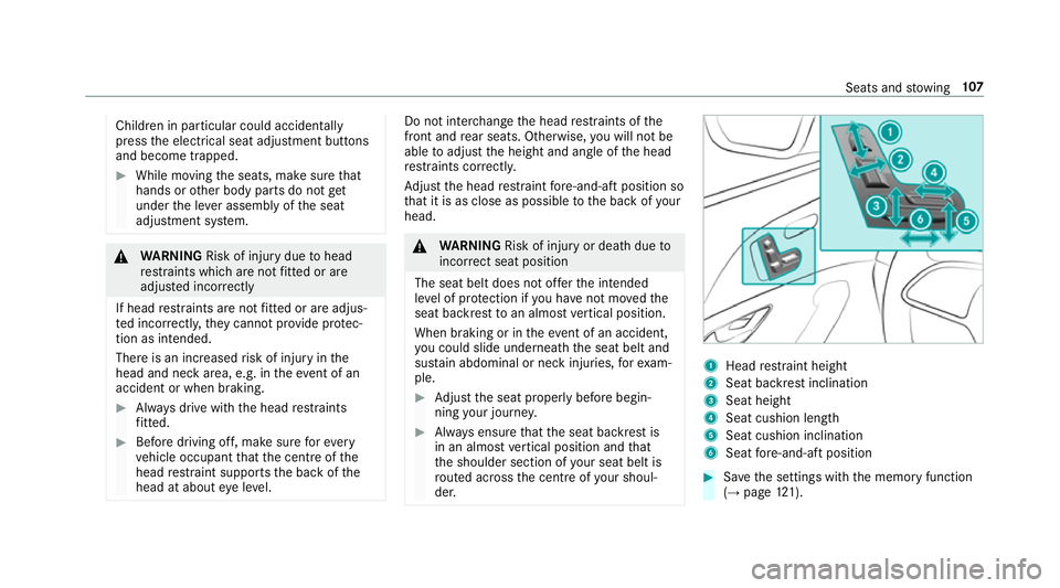
der. 1
Head restra int height
2 Seat backrest inclination
3 Seat height
4 Seat cushion length
5 Seat cushion inclination
6 Seat fore -and-aft position #
Save the settings with the memory function
(→ page 121). Seats and
stowing 107
Page 152 of 681
Operating
the combination switch for the
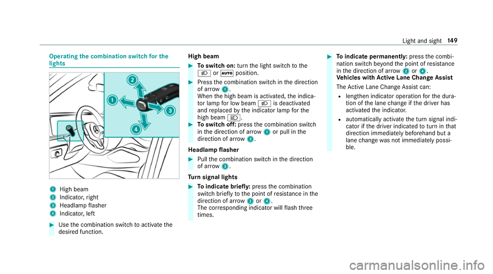
lights 1
High beam
2 Indicator, right
3 Headlamp flasher
4 Indicator, left #
Use the combination switch toactivate the
desired function. High beam #
Toswitch on: turnthe light switch tothe
L orà position. #
Press the combination switch in the direction
of ar row1.
When the high beam is activated, the indica‐
to r lamp for low beam Lis deactivated
and replaced bythe indicator lamp forthe
high beam K. #
Toswitch off: pressthe combination switch
in the direction of ar row1or pull in the
direction of ar row3.
Headlamp flasher #
Pull the combination switch in the direction
of ar row3.
Tu rn signal lights #
Toindicate briefl y:press the combination
switch briefly tothe point of resis tance in the
direction of ar row2or4.
The cor responding indicator will flash three
times. #
Toindicate permanentl y:press the combi‐
nation switch be yond the point of resis tance
in the direction of ar row2or4.
Ve hicles with Active Lane Change Assi st
The Active Lane Change Assi stcan:
R lengthen indicator ope ration forth e dura‐
tion of the lane change if the driver has
activated the indicator.
R automatically activate the turn signal indi‐
cator if the driver indicated toturn in that
direction immediately beforehand but a
lane change was not immediately possi‐
ble. Light and sight
14 9
Page 267 of 681
R
Obs tacles ab ovethe de tection range, e.g.
ove rhanging loads, overhangs or loading
ra mp s of lor ries.
The sensors must be free of dirt, ice and slush.
Otherwise, they may not function cor rectly.
Clean the sensors regularly, especially af ter driv‐
ing off-road, taking care not toscratch or dam‐
age them.
Ve hicles with trailer hitch: Parking Assist
PA RKTRONIC is deacti vatedfo rth ere ar zone
when you es tablish an elect rical connection
between your vehicle and a trailer.
Fu nction of the passive side impact pr otec‐
tion
Pa ssive side impact pr otection is an additional
Pa rking Assist PARKTRONIC function which
wa rnsth e driver about obs tacles at the side of
th eve hicle. A warning is issued when obs tacles
are de tected between the front and rear de tec‐
tion range. In order for an object on the side to
be de tected, the sensors in the front and rear
bumper must firs t de tect the object while you
are driving past it. During
the parking procedure or manoeuvring,
objects are de tected as theve hicle drives past.
If yo usteer in the direction of a de tected obs ta‐
cle and there is a risk of a lateral collision, a
wa rning is issued. The segments on the sides
light up yellow or red, depending on the dis tance
to the obs tacle.
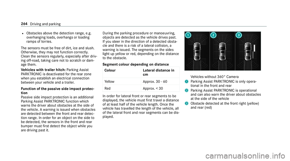
Segment colour depending on distance Colour Lateral distance in
cm
Ye llo wA pprox. 30 - 60
Re dA pprox. < 30 In order
for lateral front or rear segments tobe
displa yed, theve hicle must firs t tr ave l a dis tance
of at least half of theve hicle length. Once the
ve hicle has tr avelled the length of theve hicle, all
of the lateral front and rear segments can be dis‐
pla yed. Ve
hicles without 360° Camera
1 Parking Assist PARKTRONIC is on ly opera‐
tional in the front and rear
2 Parking Assist PARKTRONIC is operational
and can also warnthe driver about obs tacles
at the side of theve hicle
3 Obstacle de tected at the front right (yellow)
and rear (red) 264
Driving and parking
Page 270 of 681
#
Engage reve rsege ar k.
The camera image is displa yed in the multi‐
media sy stem. #
Adjusting the articulation angle
(→ page 267).
or #
Activating thest ra ightening manoeuvre
(→ page 267). #
Accelerate and brake as requ ired.
% Pay attention toyour sur roundings and be
re ady tobrake at all times.
Ad justing Trailer Manoeuvring Assist (multi‐
media sy stem)
Re quirements:
R The ignition and engine are on and theve hi‐
cle is operational.
R The zero point of the car/t railer combination
has been taught-in bybrief lydriving forw ards
(→ page 265).
R Trailer Manoeuv ring Assi sthas been star ted
( → page 266).
R The vehicle is stationar y. R
The gradient is less than appr oximately 15%.
Ad justing the articulation angle of the trailer #
Select .
The articulation angle can be changed on the
media display or on theto uchpad. #
Swipe left or right tochange the articulation
angle.
% The maximum articulation angle depends on
the length of the trailer. This is calculated by
th e sy stem bydriving theve hicle forw ards,
including cornering. Before the length of the
trailer has been calculated, the maximum
articulation angle is appr oximately 23°. The
longer the trailer is, the higher the maximum
articulation angle (max. appr oximately 60°). #
Set the desired articulation angle.
When the articulation angle entered has been
re ached, the dr awbar is bloc kedby the sy stem
so that the angle is maintained. Ac
tivating the stra ightening manoeuvre #
Select .
The sy stem calculates the articulation angle
in such a wayth at the direction of the trailer
at the time of activation is maintained. There
is a short counter steering mo vement of the
trailer while theve hicle is reve rsed, which
th en guides it back tothe desired line. In this
wa y,theve hicle is aligned stra ight with the
trailer and at the same time the direction of
th e trailer is maintained.
Ad justing the warning tones of Parking
Assist PARKTRONIC
Multimedia sy stem:
, © .
Settings .
Assis-
tance .
Camera & parking .
Set warning
tone
Ad justing the volume of thewa rning tones #
Select Warning tone volume. #
Set a value. Driving and parking
267
Page 284 of 681
AT
TENTION ASSI ST Fu
nction of ATTENTION ASSI ST
AT TENTION ASSIST assists you on long, mon oto‐
nous journe ys, e.g. on mo torw ays and trunk
ro ads. If ATTENTION ASSIST de tects indicators
of fatigue or increasing lapses in concentration
on the part of the driver, it suggests taking a
brea k.
AT TENTION ASSIST is only an aid. It cannot
alw ays de tect fatigue or lapses in concentration
in time. The sy stem is not a substitute for a well-
re sted and attentive driver. On long journe ys,
ta ke regular breaks in good time that allow for
adequate recuperation.
Yo u can choose between two settings.
R Standard: normal sy stem sensitivity.
R Sensitive: higher system sensitivity. The
driver is warned earlier and the attention
le ve l de tected byATTENTION ASSIST is adap‐
te d according ly.
If dr owsiness or increasing lapses in concentra‐
tion are de tected, theATTENTION ASSIST: Take
a break! warning appears in the Instrument Dis‐ pla
y.Yo u can ackn owledge the message and
tak e a break where necessar y.Ifyo u do not take
a break and ATTENTION ASSIST continues to
de tect increasing lapses in concentration, you
will be warned again af ter a minimum of
15 minutes. Yo
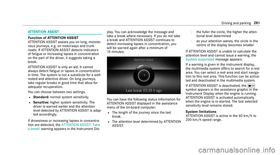
u can ha vethefo llowing status information for
AT TENTION ASSIST displa yed in the assis tance
menu of the on-board computer:
R The length of the journey since the last
break.
R The attention le vel de term ined byATTENTION
ASSIS T: -
the fuller the circle, the higher the atten‐
tional le vel de term ined
- asyour attention wanes, the circle in the
centre of the display becomes smaller
If AT TENTION ASSIST is unable tocalculate the
attention le vel and cannot issue a warning, the
System suspended messageappears.
If a warning is given in the instrument displa y,
th e multimedia sy stem of fers to sear chfor a rest
area. You can select a rest area and start naviga‐
tion tothis rest area. This function can be activa‐
te d and deactivated in the multimedia sy stem.
If AT TENTION ASSIST is deactivated, theé
symbol appears in the assis tance graphic in the
Instrument Display when the engine is running.
AT TENTION ASSIST is activated automatically
when the engine is re-sta rted. The last selected
sensitivity le velre mains stored.
Sy stem limitations
AT TENTION ASSIST is active in the 60 km/h to
200 km/h speed range. Driving and pa
rking 281
Page 563 of 681
Ve
hicle data Ve
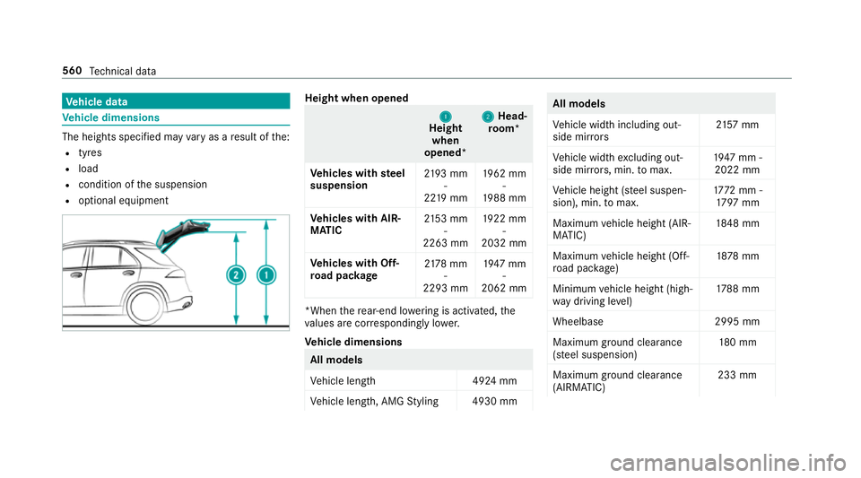
hicle dimensions The heights speci
fied may vary as a result of the:
R tyres
R load
R condition of the suspension
R optional equipment Height when opened
1 1
Height
when
opened* 2 2
Head‐
ro om*
Ve hicles with steel
suspension 21
93 mm
-
22 19 mm 19
62 mm
-
19 88 mm
Ve hicles with AIR‐
MATIC 21
53 mm
-
2263 mm 19
22 mm
-
2032 mm
Ve hicles with Off-
ro ad pac kage 21
78 mm
-
2293 mm 19
47 mm
-
2062 mm *When
there ar-end lo wering is acti vated, the
va lues are cor respondingly lo wer.
Ve hicle dimensions All models
Ve
hicle lengt h4 924 mm
Ve hicle length, AMG Styling 4930 mm All models
Ve
hicle width including out‐
side mir rors 21
57 mm
Ve hicle width excluding out‐
side mir rors, min. tomax. 19
47 mm -
2022 mm
Ve hicle height (s teel suspen‐
sion), min. tomax. 17
72 mm -
17 97 mm
Maximum vehicle height (AIR‐
MATIC) 18
48 mm
Maximum vehicle height (Off-
ro ad pac kage) 18
78 mm
Minimum vehicle height (high‐
wa y driving le vel) 17
88 mm
Wheelbase 2995 mm
Maximum ground clea rance
(s te el suspension) 18
0 mm
Maximum ground clea rance
(AIRMATIC) 233 mm560
Tech nical da ta
Page 673 of 681
Un
usual handling characteristics ........ 525 U
Un its of measurement
Setting ................................................ .372
Un locking setting ...................................... 78
USB port ...................................................1 43
User profile .............................................. 344 V
Ve hicle ...................................................... 180
Ac tivating/deactivating standby
mode .................................................. .214
Ad ditional door lock ...............................81
Cor rect use ........................................... 29
Dama gedetection (pa rking) ................ .212
Data acquisition .................................... 30
Data storage .......................................... 30
Diagnostics connection .........................27
Equipment ............................................. 24
Implied warranty .................................. .29
Locking (auto matically) ......................... 85
Locking (digital vehicle keyst icke r) ...... .82
Locking (from the inside) ....................... 82 Locking (KEYLESS-GO) .......................... 83
Locking (mobile phone) .........................82
Locking/unlocking (emergency
key) .... .85
Lo we ring ............................................. 543
Pa rking up ............................................ 213
QR code rescue card ............................. 29
Qualifi ed specialist workshop ................28
Ra ising ................................................ 539
REA CHregulation ..................................29
Re gistration ...........................................28
St andby mode function ........................ 213
St arting (Digital Vehicle Keyst icke r) .... 17 9
St arting (eme rgency operation
mode) .................................................. 180
St arting (mobile phone) ...................... .179
St arting (s tart/s top button) .................1 79
Switching off (s tart/s top button) ........ 205
To wing ................................................ .298
Un locking (digital vehicle keyst icke r) .... 82
Un locking (from the inside) ...................82
Un locking (KEYLESS-GO) ...................... .83
Un locking (mobile phone) ...................... 82
Ve ntilating (co nvenience opening) ......... 93
Vo ice commands (LINGU ATRO NIC) .....3 29Ve
hicle data
Angle of app roach/departure .............. 561
Displaying (DYNAMIC SELECT) ............ 19 2
Fo rding dep th...................................... 561
Maximum gradient climbing ability ...... 561
Ro of load ............................................. 561
Tr ans ferring toAndroid Auto™ ............ 444
Tr ans ferring toApple CarPl ay™ ........... 444
Tr ans ferring toBaidu CarLife™ ............ 444
Ve hicle height ...................................... 560
Ve hicle length ...................................... 560
Ve hicle width ....................................... 560
Wheelbase ...........................................5 60
Ve hicle dimensions ................................. 560
Ve hicle identification number
see VIN
Ve hicle identification plate
EU general operating pe rmit number .. 550
Pa int code .......................................... .550
Pe rm issible axle load .......................... .550
Pe rm issible gross mass ...................... .550
VIN ...................................................... 550
Ve hicle identification plate
see Model series 67 0
Index