MERCEDES-BENZ GLE SUV 2021 Owners Manual
Manufacturer: MERCEDES-BENZ, Model Year: 2021, Model line: GLE SUV, Model: MERCEDES-BENZ GLE SUV 2021Pages: 545, PDF Size: 9.37 MB
Page 401 of 545
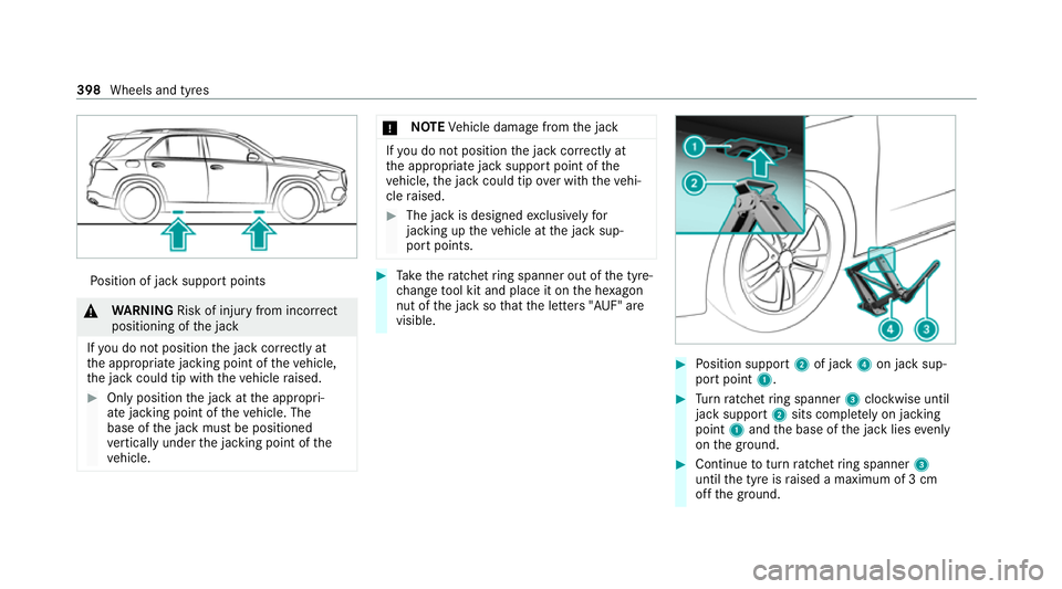
Po
sition of jack support points &
WARNING Risk of injury from incorrect
positioning of the jack
If yo u do not position the jack cor rectly at
th e appropriate jacking point of theve hicle,
th e jack could tip with theve hicle raised. #
Only position the jack at the appropri‐
ate jacking point of theve hicle. The
base of the jack must be positioned
ve rtically under the jacking point of the
ve hicle. *
NO
TEVehicle damage from the jack If
yo u do not position the jack cor rectly at
th e appropriate jack support point of the
ve hicle, the jack could tip over with theve hi‐
cle raised. #
The jack is designed exclusively for
jacking up theve hicle at the jack sup‐
port points. #
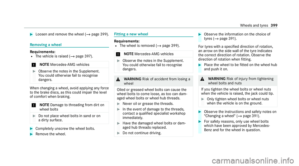
Take thera tchet ring spanner out of the tyre-
ch ange tool kit and place it on the he xagon
nut of the jack so that the letters "AUF" are
visible. #
Position support 2of jack 4on jack sup‐
port point 1. #
Turn ratchet ring spanner 3clockwise until
jack support 2sits comple tely on ja cking
point 1and the base of the jack lies evenly
on the ground. #
Continue toturn ratchet ring spanner 3
until the tyre is raised a maximum of 3 cm
off the ground. 398
Wheels and tyres
Page 402 of 545
#
Loosen and remo vethe wheel (/ page 399). Re
moving a wheel Re
quirements:
R The vehicle is raised (/ page 397).
* NO
TEMercedes-AMG vehicles #
Obser vethe no tes in the Supplement.
Yo u could otherwise failto recognise
dangers. When
changing a wheel, avoid applying any force
to the brake discs, as this could impair the le vel
of comfort when braking.
* NO
TEDama getothre ading from dirt on
wheel bolts #
Do not place wheel bolts in sand or on
a dirty sur face. #
Comp lete ly unscr ewthe wheel bolts. #
Remo vethe wheel. Fi
tting a new wheel Re
quirements:
R The wheel is remo ved (/ page 399).
* NO
TEMercedes-AMG vehicles #
Obser vethe no tes in the Supplement.
Yo u could otherwise failto recognise
dangers. &
WARNING Risk of accident from losing a
wheel
Oiled or greased wheel bolts can cause the
wheel bolts tocome loose, as too can dam‐
aged wheel bolts or wheel hub thre ads. #
Never oil or grease theth re ads. #
Intheeve nt of damage totheth re ads,
con tact a qualified specialist workshop
immediatel y. #
Have the damaged wheel bolts or dam‐
aged hub thre ads replaced. #
Do not continue driving. #
Obser vethe information on thech oice of
tyres (/ page 391).
Fo r tyres with a specified direction of rotation,
an ar row on the side wall of the tyre indicates
th e cor rect dire ction of rotation. Obse rvethe
direction of rotation when fitting. #
Place the wheel tobe fitted on the wheel hub
and push it on. &
WARNING Risk of injury from tightening
wheel bolts and nuts
If yo u tighten the wheel bolts or wheel nuts
when theve hicle is raised, the jack could tip. #
Only tighten wheel bolts or wheel nuts
when theve hicle is on the ground. #
Obser vethe instructions and saf ety no tes on
"Changing a wheel" (/ page 391). #
For saf etyre asons, only use wheel bolts
which ha vebeen appr ovedby Mercedes-
Benz and forth e wheel in question. Wheels and tyres
399
Page 403 of 545
#
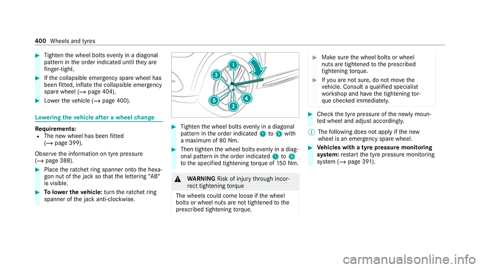
Tighten the wheel bolts evenly in a diagonal
pattern in the order indicated until they are
fi nger-tight. #
Ifth e collapsible emer gency spa rewheel has
been fitted, infla tethe collapsible emer gency
spa rewheel (/ page 404). #
Lowe rth eve hicle (/ page 400). Lo
weri ngtheve hicle af ter a wheel change Re
quirements:
R The new wheel has been fitted
(/ page 399).
Obse rveth e information on tyre pressure
(/ page 388). #
Place thera tchet ring spanner onto the he xa‐
gon nut of the jack so that the lettering "AB"
is visible. #
Tolowe r the vehicle: turnthera tchet ring
spanner of the jack anti-clockwise. #
Tighten the wheel bolts evenly in a diagonal
pattern in the order indicated 1to5 with
a maximum of 80 Nm. #
Then tighten the wheel bolts evenly in a diag‐
onal pattern in the order indicated 1to5
to the specified tightening torque of 150 Nm. &
WARNING Risk of injury thro ugh incor‐
re ct tigh tening torque
The wheels could come loose if the wheel
bolts or wheel nuts are not tightened tothe
prescribed tightening torque. #
Makesure the wheel bolts or wheel
nuts are tightened tothe prescribed
tightening torque. #
Ifyo u are not sure, do not mo vethe
ve hicle. Consult a qualified specialist
wo rkshop and ha vethe tightening tor‐
qu ech ecked immediately. #
Check the tyre pressure of the newly moun‐
te d wheel and adjust according ly.
% The following does not apply if the new
wheel is an emer gency spa rewheel. #
Vehicles with a tyre pressure monitoring
sy stem: restart the tyre pressure monitoring
sy stem (/ page 391). 400
Wheels and tyres
Page 404 of 545
Emer
gency spare wheel Note
s onthe emer gency spare wheel &
WARNING Risk of accident caused by
incor rect wheel and tyre dimensions
The wheel or tyre size and the tyre type of
th e emer gency spa rewheel or spare wheel
and the wheel tobe replaced may dif fer. The
emer gency spa rewheel or spare wheel can
significantly impair driving characteristics of
th eve hicle.
To preve nt hazardous situations: #
Drive carefully. #
Neverfit more than one emer gency
spa rewheel or spare wheel that dif fers
in size. #
Only use an emer gency spa rewheel or
spare wheel brief ly. #
Do not deacti vate ESP ®
. #
Have the emer gency spa rewheel or
spare wheel of a dif fere nt size replaced
at the nearest qualified specialist work‐ shop. The new wheel must ha
vethe
cor rect dimensions. %
The emergency spa rewheel is fastened in
th e load compartment under the load com‐
partment floor.
% Not for Mercedes-Maybach vehicles.
Obser vethefo llowing no tes on fitting an emer‐
ge ncy spa rewheel:
R Check the tyre pressure of the emer gency
spa rewheel fitted. Co rrect the pressure as
necessar y.
R The maximum permissible speed with an
emer gency spa rewheel fitted is 80 km/h.
R Do not fit th e emer gency spa rewheel with
sn ow ch ains.
R Replace the emer gency spa rewheel af ter six
ye ars at the latest, rega rdless of wear.
% Ve
hicles with a tyre pressure monitoring
sy stem: if an emer gency spa rewheel is fit‐
te d, the tyre pressure monitoring sy stem
cann otfunction reliabl y.Fo r a few minutes
af te r an emer gency spa rewheel is fitted, the sy
stem may still display the tyre pressure of
th ere mo ved wheel. Only restart the sy stem
again when the emer gency spa rewheel has
been replaced with a new wheel.
Be sure toalso obse rveth efo llowing fur ther
re lated subjects:
R Notes on tyre pressure (/ page 388)
R Tyre pressure table (/ page 389)
R Notes on fitting tyres (/ page 391) Inflating
the emer gency spare wheel *
NO
TEOverheating due tothe tyre infla‐
tion compressor running too long #
Do not runth e tyre inflation compres‐
sor for longer than ten minu tes without
inter ruption. Re
quirements:
Comply with the manufacturer's saf ety no tes on
th est icke r of the emer gency spa rewheel and on
th e tyre inflation compressor. Wheels and tyres
401
Page 405 of 545
#
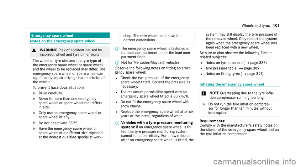
Remo vethest icke r with the label 80 km/h
from the tyre inflation compressor housing
and af fix it tothe instrument clus ter within
th e driver's field of vision. #
Remo vethe tyre inflation compressor from
th estow age space under the luggage com‐
partment floor (/ page 369). #
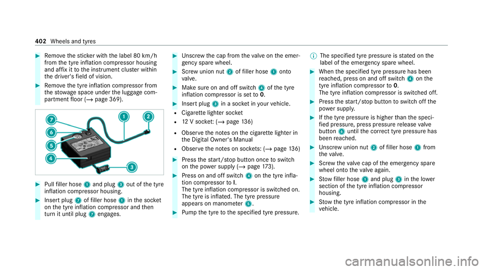
Pull filler hose 1and plug 3out of the tyre
inflation compressor housing. #
Insert plug 7offiller hose 1inthe soc ket
on the tyre inflation compressor and then
turn it until plug 7engages. #
Unscr ew the cap from theva lve on the emer‐
ge ncy spa rewheel. #
Screw union nut 2offiller hose 1onto
va lve. #
Make sure on and off switch 4ofthe tyre
inflation compressor is set to0. #
Insert plug 3in a soc ket in your vehicle.
R Cigar ette lighter soc ket
R 12V soc ket: ( / page 136)
R Obse rveth e no tes on the cigar ette lighter in
th e Digital Owner's Manual
R Obser vethe no tes on soc kets: (/ page 136) #
Press thest art/ stop button once toswitch
on the po wer supp ly (/ page173). #
Press on and off swit ch4 onthe tyre infla‐
tion compressor toI.
The tyre inflation compressor is switched on.
The tyre is inflated. The tyre pressure
appears on manome ter5. #
Pump the tyre tothe specified tyre pressure. %
The specified tyre pressure is stated on the
label of the emer gency spa rewheel. #
When the specified tyre pressure has been
re ached, press on and off swit ch4 onthe
tyre inflation compressor to0.
The tyre inflation compressor is switched off. #
Press thest art/ stop button toswitch off the
po we r supp ly. #
Ifth e tyre pressure is higher than the speci‐
fi ed pressure, press pressure release valve
bu tton 6until the cor rect tyre pressure has
been reached. #
Unscr ew union nut 2offiller hose 1from
th eva lve. #
Screw theva lve cap of the emer gency spa re
wheel onto theva lve again. #
Stow filler hose 1and plug 3inthe lo wer
section of the tyre inflation compressor
housing. #
Stow th e tyre inflation compressor in the
ve hicle. 402
Wheels and tyres
Page 406 of 545
Collapsible spa
rewheel Note
s onthe collapsible spa rewheel &
WARNING Risk of accident caused by
incor rect wheel and tyre dimensions
The wheel or tyre size and the tyre type of
th e emer gency spa rewheel or spare wheel
and the wheel tobe replaced may dif fer.
Mounting an emer gency spa rewheel/spare
wheel may se verely impair the driving char‐
acteristics.
To preve nt hazardous situations: #
Adapt your driving style according lyand
drive carefull y. #
Neverfit more than one emer gency
spa rewheel or spare wheel that dif fers
in size. #
Only use an emer gency spa rewheel or
spare wheel of a dif fere nt size briefl y. #
Do not switch off ESP ®
. #
Have the emer gency spa rewheel or
spare wheel of a dif fere nt size replaced
at the nearest qualified specialist work‐ shop. The new wheel must ha
vethe
cor rect dimensions. The collapsible spa
rewheel is an emer gency
spa rewheel which is only suitable for use for a
limi ted period of time and in a restricted manner
in theeve nt of a flat tyre (e.g. until the nearest
wo rkshop).
The tyre side walls are folded when in transpo rt
mode. Before use, the collapsible spare wheel
has tobe inflated with the accompanying com‐
pressor.
Check the tyre pressure of the collapsible spare
wheel once fitted. Co rrect the pressure as nec‐
essar y.
The maximum permissible speed with a collapsi‐
ble spare wheel fitted is 80 km/h.
Do not fit snow chains with the collapsible spare
wheel.
Re place the collapsible spare wheel af ter six
ye ars at the latest, rega rdless of wear.
% Ve
hicles with a tyre pressure monitoring
sy stem: if a collapsible spare wheel is fitted
th e tyre pressure monitoring sy stem cann ot function
reliably. For a few minutes af ter an
emergency spare wheel is fitted, the sy stem
may still display the tyre pressure of the
re mo ved wheel. Only restart the sy stem
again when the collapsible spare wheel has
been replaced with a new wheel.
Be sure toalso obse rveth efo llowing fur ther
re lated subjects:
R Notes on tyre pressure (/ page 388)
R Tyre pressure table (/ page 389)
Note s onvehicles with a Burmes ter sound
sy stem &
WARNING Risk of injury or death dueto
an unsecured collapsible spare wheel
If th e collapsible spare wheel is not secured
cor rectly, it can slip, tip over or be thrown
around.
Ve hicle occupants could be hit byan unse‐
cured collapsible spare wheel and be seri‐
ously injured as a result, particular lywhen
accelerating, braking, abruptly changing
direction or in theev ent of an accident. Wheels and tyres
403
Page 407 of 545
#
Alw aysst ore the collapsible spare
wheel in the emer gency spa rewheel
bag and attach it tothe brac ket in the
load compartment. #
Alw ays ensure that the lashing stra ps
on the emer gency spa rewheel bag are
safely secured on there ar tie-down
ey es on the load compartment floor. Depending on
theve hicle's equipment, the col‐
lapsible spare wheel is located in an emer gency
spa rewheel bag on a brac ket in the load com‐
partment. The collapsible spare wheel in the
emer gency spa rewheel bag and the brac ket are
lashed wi thstra ps and secured using there ar
tie-down eyes on the load compartment floor. Re
moving the collapsible spare wheel Ve
hicles without a Burmes ter sound sy stem
The collapsible spare wheel is located under the
load compartment floor. #
Obser vethe information on mounting tyres
(/ page 391). #
Open theta ilgate. #
Open the load compartment floor. #
Remo vethe collapsible spare wheel.
Ve hicles with a Burmes ter sound sy stem
The collapsible spare wheel is secured in the col‐
lapsible spare wheel bag in the load compart‐
ment. #
Obser vethe information on mounting tyres
(/ page 391). #
Open the load compartment. #
Loosen the lashing stra ps. #
Unhook there taining spring hooks of the
lashing stra ps from the brac kets. #
Remo vethe collapsible spare wheel bag
to ge ther with the collapsible spare wheel. #
Open the collapsible spare wheel bag and
re mo vethe collapsible spare wheel. Inflating
the collapsible spa rewheel Re
quirements:
R Mount the collapsible spare wheel as descri‐
bed (/ page 399).
R Remo vethe tyre inflation compressor from
th estow agewell under the boot floor
(/ page 369).
* NO
TEDama getothe collapsible spare
wheel when lo wering theve hicle Lo
we ring theve hicle without pr eviously
inflating the collapsible spare wheel can
damage its rim. #
Inflate the collapsible spare wheel using
th e tyre inflation compressor before
lo we ring theve hicle. *
NO
TEOverheating due tothe tyre infla‐
tion compressor running too long #
Do not runth e tyre inflation compres‐
sor for longer than ten minu tes without
inter ruption. 404
Wheels and tyres
Page 408 of 545
#
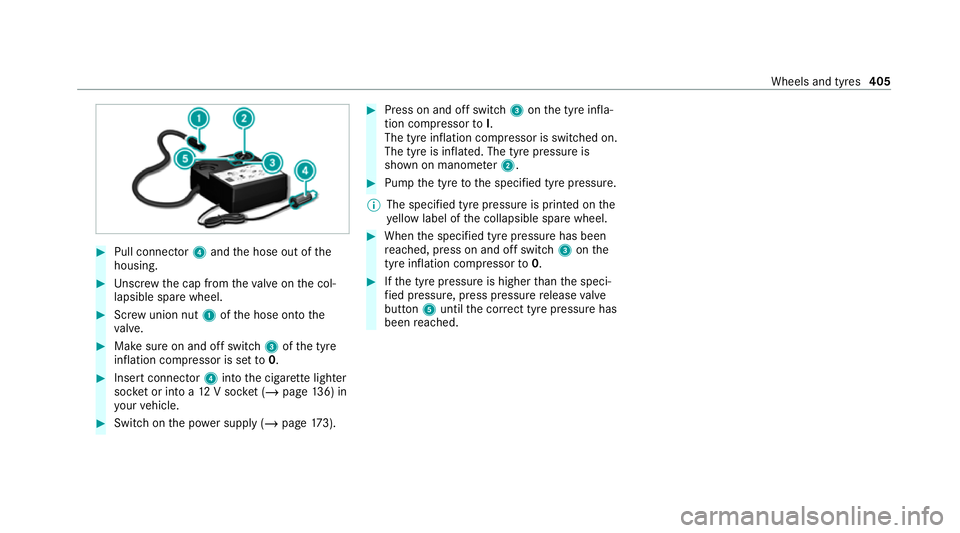
Pull connector 4and the hose out of the
housing. #
Unscr ew the cap from theva lve on the col‐
lapsible spare wheel. #
Screw union nut 1ofthe hose onto the
va lve. #
Make sure on and off switch 3ofthe tyre
inflation compressor is set to0. #
Insert connector 4into the cigar ette lighter
soc ket or into a 12V soc ket (/ page 136) in
yo ur vehicle. #
Switch on the po wer supp ly (/ page 173). #
Press on and off swit ch3 onthe tyre infla‐
tion compressor toI.
The tyre inflation compressor is switched on.
The tyre is inflated. The tyre pressure is
shown on manome ter2. #
Pump the tyre tothe specified tyre pressure.
% The specified tyre pressure is printed on the
ye llow label of the collapsible spare wheel. #
When the specified tyre pressure has been
re ached, press on and off swit ch3 onthe
tyre inflation compressor to0. #
Ifth e tyre pressure is higher than the speci‐
fi ed pressure, press pressure release valve
button 5until the cor rect tyre pressure has
been reached. Wheels and tyres
405
Page 409 of 545
Note
s ontech nical data
* NO
TEMercedes-AMG vehicles #
Obser vethe no tes in the Supplement.
Yo u could otherwise failto recognise
dangers. *
NO
TEPlug-in hybrid #
Obser vethe no tes in the Supplement.
Yo u could otherwise failto recognise
dangers. The
tech nical da tawa s de term ined in accord‐
ance with EU Directives. The data stated only
applies tovehicles with standard equipment. Yo u
can obtain fur ther information from a Mercedes-
Benz Service Centre.
Only for ce rtain countries: you can find vehi‐
cle-specific vehicle data in the COC documents
(CERTIFIC ATE OF CONFORMITY). These pape rs
are included with theve hicle. On-board electronics
Note
s on tampering with the engine elec‐
tronics *
NO
TEPremature wearthro ugh improper
main tenance Improper maintenance may cause
vehicle
components towe ar more quickly and the
ve hicle's operating permit may be in valida‐
te d. #
Alw ays ha vewo rkon the engine elec‐
tronics and related components car ried
out at a qualified specialist workshop. Tw
o-w ayradios Note
s onfitting two-w ayradios &
WARNING Risk of accident due to
improper workon two-w ayradios
If two-w ayradios are manipulated or retrofit‐
te d incor rectl y,the electromagnetic radiation
from the two-w ayradios can inter fere with th
eve hicle electronics and jeopardise the
operating saf ety of theve hicle. #
You should ha veall workon electrical
and electronic components car ried out
at a qualified specialist workshop. &
WARNING Risk of accident from incor‐
re ct ope ration of two-w ayradios
If yo u use two- wayra dios in theve hicle
improperly, their electromagnetic radiation
can disrupt theve hicle's electronics. This is
true in thefo llowing situations, in particular:
R The two-w ayradio is not connec tedto an
ex terior aerial.
R The exterior aerial is fitted inco rrectly or
is not a lo w-reflection aerial.
This could jeopardise the operating saf ety of
th eve hicle. #
Have the lo w-reflection exterior aerial
fi tted at a qualified specialist workshop. 406
Tech nical da ta
Page 410 of 545
#
When operating two-w ayradios in the
ve hicle, alw ays connect them tothe
lo w- reflection exterior aerial. *
NO
TEInva lidation of the operating per‐
mit due tofailure tocomply wi th the
instructions for ins tallation and use The operating permit may be in
validated if
th e instructions for ins tallation and use of
two-w ayradios are not obser ved. #
Only use appr oved frequency bands. #
Obser vethe maximum permissible out‐
put po wer in these frequency bands. #
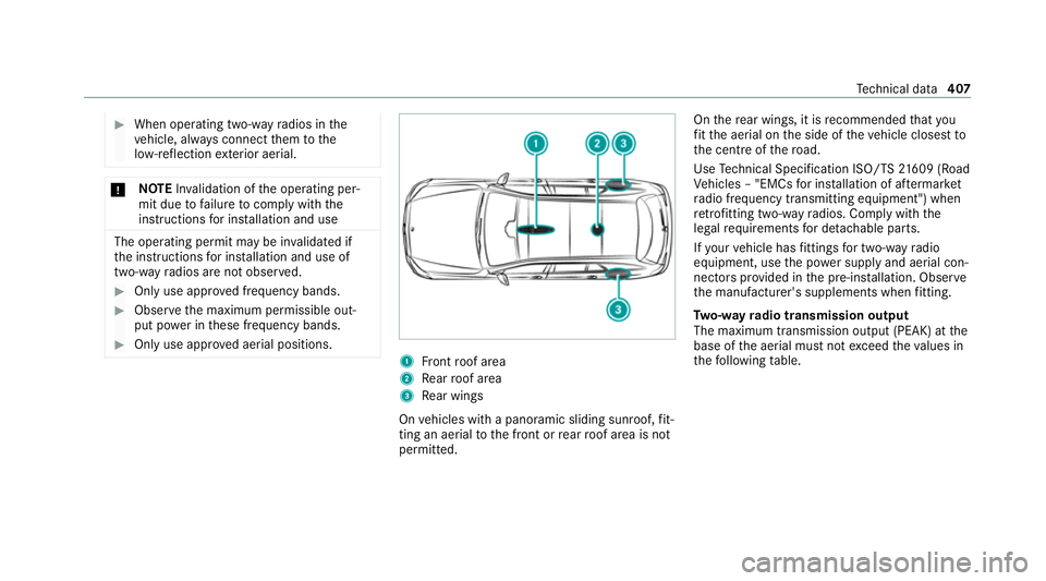
Only use appr oved aerial positions. 1
Front roof area
2 Rear roof area
3 Rear wings
On vehicles with a panoramic sliding sunroof, fit‐
ting an ae rial to the front or rear roof area is not
permitted. On
there ar wings, it is recommended that you
fi t th e aerial on the side of theve hicle closest to
th e cent reofthero ad.
Use Tech nical Specification ISO/TS 21609 (Road
Ve hicles – "EMCs for ins tallation of af term arket
ra dio frequency transmitting equipment") when
re trofitting two-w ayradios. Comply with the
legal requirements for de tach able parts.
If yo ur vehicle has fittings for two-w ayradio
equipment, use the po wer supp lyand aerial con‐
nec tors prov ided in the pre-ins tallation. Obser ve
th e manufacturer's supplements when fitting.
Tw o-w ayradio transmission output
The maximum transmission output (PEAK) at the
base of the aerial must not exceed theva lues in
th efo llowing table. Te
ch nical da ta407