rear view mirror MERCEDES-BENZ GLK-Class 2015 X204 User Guide
[x] Cancel search | Manufacturer: MERCEDES-BENZ, Model Year: 2015, Model line: GLK-Class, Model: MERCEDES-BENZ GLK-Class 2015 X204Pages: 386, PDF Size: 7.16 MB
Page 195 of 386
then have to steer and merge into traffic on
your own. PARKTRONIC is still available.
Canceling Active Parking Assist You can cancel Active Parking Assist at any
time.
X Stop the movement of the multifunction
steering wheel or steer yourself.
Active Parking Assist will be canceled at
once. The Park Assist Canceled Park Assist Canceled mes-
sage appears in the multifunction display.
or
X Press the PARKTRONIC button on the cen-
ter console (Y page 188).
PARKTRONIC is switched off and Active
Parking Assist is immediately canceled.
The Park Assist Canceled Park Assist Canceled message
appears in the multifunction display.
Active Parking Assist is canceled automati-
cally if: R the electric parking brake is engaged
R transmission position Pis selected
R parking using Active Parking Assist is no
longer possible
R you are driving faster than 6 mph (10 km/h)
R a wheel spins, ESP ®
intervenes or fails. The
00E5 warning lamp lights up in the instru-
ment cluster.
A warning tone sounds. The parking symbol
disappears and the multifunction display
shows the Park Assist Canceled
Park Assist Canceled mes-
sage.
If Active Parking Assist is canceled, you must
steer again yourself.
If a system malfunction occurs, the vehicle is braked to a standstill. To drive on, depress the
accelerator again.
Towing a trailer For vehicles with a trailer tow hitch, the min-
imum length for parking spaces is slightly
increased. If you have attached a trailer to your vehicle,
you should not use Active Parking Assist.
Once the electrical connection is established
between your vehicle and the trailer, Active
Parking Assist is no longer available. PARK-
TRONIC is deactivated for the rear area. Rear view camera
General notes 0043
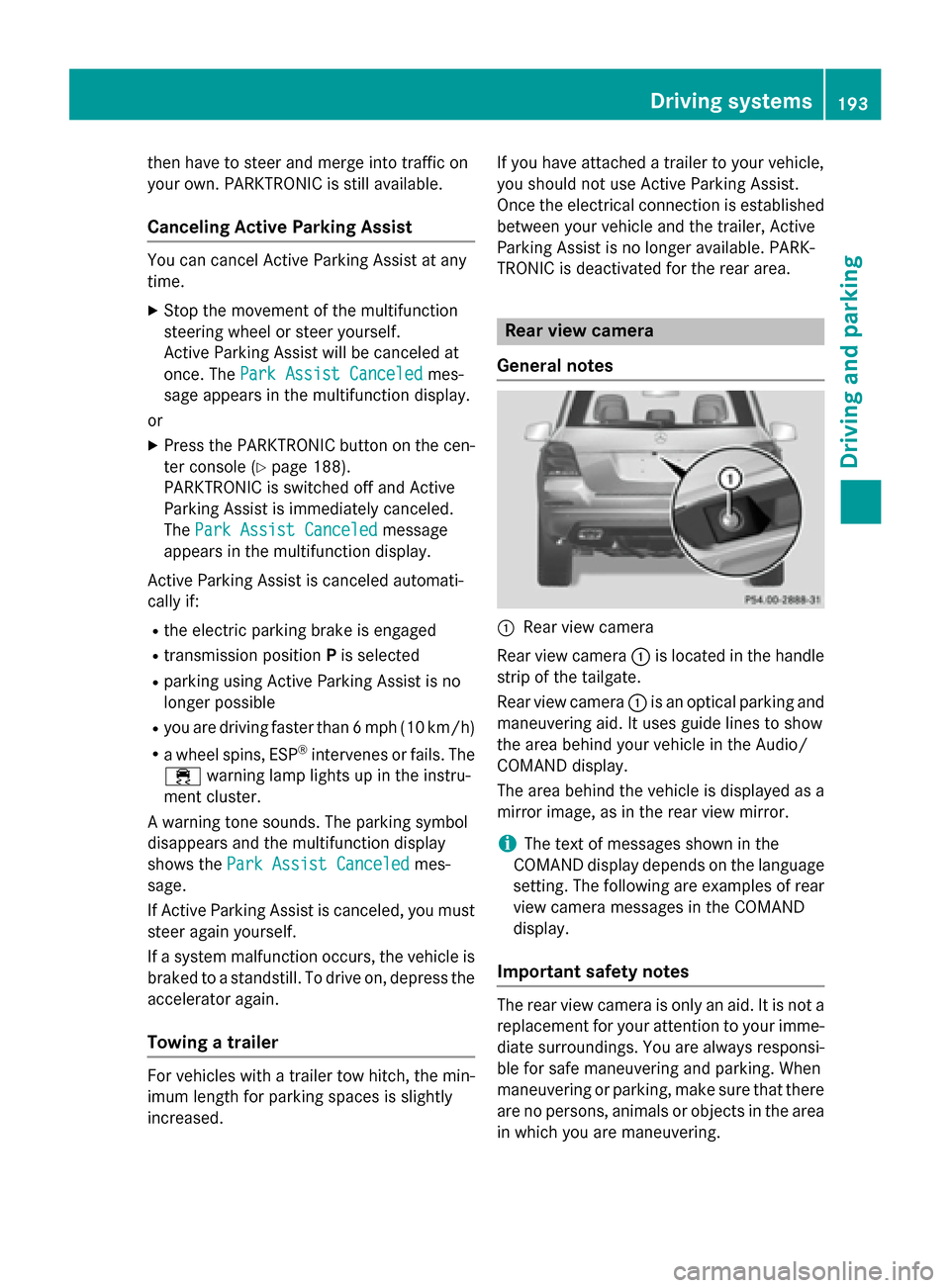
Rear view camera
Rear view camera 0043is located in the handle
strip of the tailgate.
Rear view camera 0043is an optical parking and
maneuvering aid. It uses guide lines to show
the area behind your vehicle in the Audio/
COMAND display.
The area behind the vehicle is displayed as a
mirror image, as in the rear view mirror.
i The text of messages shown in the
COMAND display depends on the language
setting. The following are examples of rear view camera messages in the COMAND
display.
Important safety notes The rear view camera is only an aid. It is not a
replacement for your attention to your imme- diate surroundings. You are always responsi-
ble for safe maneuvering and parking. When
maneuvering or parking, make sure that there are no persons, animals or objects in the area
in which you are maneuvering. Driving systems
193Driving and parking Z
Page 197 of 386
0043
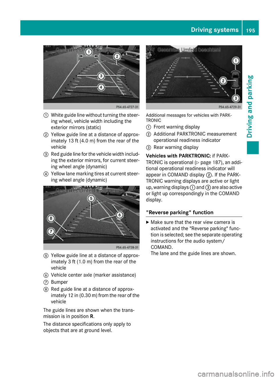
White guide line without turning the steer-
ing wheel, vehicle width including the
exterior mirrors (static)
0044 Yellow guide line at a distance of approx-
imately 13 ft (4.0 m) from the rear of the
vehicle
0087 Red guide line for the vehicle width includ-
ing the exterior mirrors, for current steer-
ing wheel angle (dynamic)
0085 Yellow lane marking tires at current steer-
ing wheel angle (dynamic) 0083
Yellow guide line at a distance of approx-
imately 3 ft (1.0 m) from the rear of the
vehicle
0084 Vehicle center axle (marker assistance)
006B Bumper
006C Red guide line at a distance of approx-
imately 12 in (0.30 m) from the rear of the
vehicle
The guide lines are shown when the trans-
mission is in position R.
The distance specifications only apply to
objects that are at ground level. Additional messages for vehicles with PARK-
TRONIC
0043
Front warning display
0044 Additional PARKTRONIC measurement
operational readiness indicator
0087 Rear warning display
Vehicles with PARKTRONIC: if PARK-
TRONIC is operational (Y page 187), an addi-
tional operational readiness indicator will
appear in COMAND display 0044. If the PARK-
TRONIC warning displays are active or light
up, warning displays 0043and 0087are also active
or light up correspondingly in the COMAND
display.
"Reverse parking" function X
Make sure that the rear view camera is
activated and the "Reverse parking" func-
tion is selected; see the separate operating
instructions for the audio system/
COMAND.
The lane and the guide lines are shown. Driving systems
195Driving and parking Z
Page 198 of 386
Backing up straight into a parking space
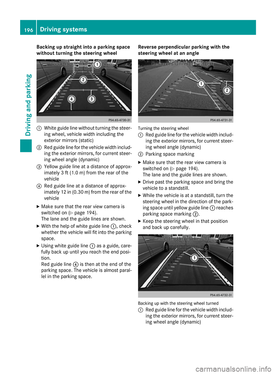
without turning the steering wheel 0043
White guide line without turning the steer-
ing wheel, vehicle width including the
exterior mirrors (static)
0044 Red guide line for the vehicle width includ-
ing the exterior mirrors, for current steer-
ing wheel angle (dynamic)
0087 Yellow guide line at a distance of approx-
imately 3 ft (1.0 m) fromthe rear of the
vehicle
0085 Red guide line at a distance of approx-
imately 12 in (0.30 m) fromthe rear of the
vehicle
X Make sure that the rear view camera is
switched on (Y page 194).
The lane and the guide lines are shown.
X With the help of white guide line 0043, check
whether the vehicle will fit into the parking space.
X Using white guide line 0043as a guide, care-
fully back up until you reach the end posi-
tion.
Red guide line 0085is then at the end of the
parking space. The vehicle is almost paral-
lel in the parking space. Reverse perpendicular parking with the
steering wheel at an angle Turning the steering wheel
0043
Red guide line for the vehicle width includ-
ing the exterior mirrors, for current steer-
ing wheel angle (dynamic)
0044 Parking space marking
X Make sure that the rear view camera is
switched on (Y page 194).
The lane and the guide lines are shown.
X Drive past the parking space and bring the
vehicle to a standstill.
X While the vehicle is at a standstill, turn the
steering wheel in the direction of the park- ing space until yellow guide line 0043reaches
parking space marking 0044.
X Keep the steering wheel in that position
and back up carefully. Backing up with the steering wheel turned
0043 Red guide line for the vehicle width includ-
ing the exterior mirrors, for current steer-
ing wheel angle (dynamic) 196
Driving systemsDriving an
d parking
Page 200 of 386
0043
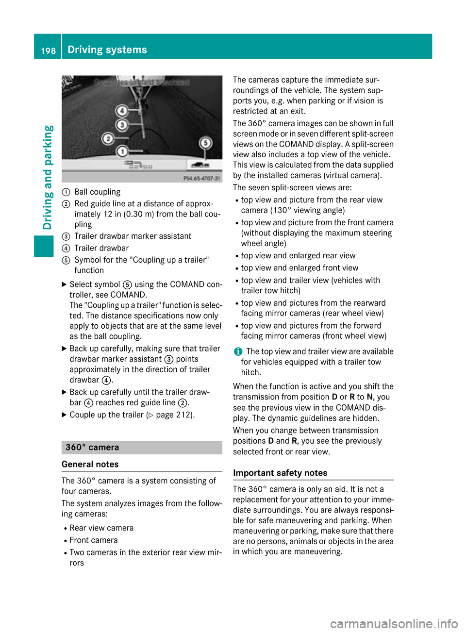
Ball coupling
0044 Red guide line at a distance of approx-
imately 12 in (0.30 m)from the ball cou-
pling
0087 Trailer drawbar marker assistant
0085 Trailer drawbar
0083 Symbol for the "Coupling up a trailer"
function
X Select symbol 0083using the COMAND con-
troller, see COMAND.
The "Coupling up a trailer" function is selec-
ted. The distance specifications now only
apply to objects that are at the same level
as the ball coupling.
X Back up carefully, making sure that trailer
drawbar marker assistant 0087points
approximately in the direction of trailer
drawbar 0085.
X Back up carefully until the trailer draw-
bar 0085reaches red guide line 0044.
X Couple up the trailer (Y page 212).360° camera
General notes The 360° camera is a system consisting of
four cameras.
The system analyzes images from the follow- ing cameras:
R Rear view camera
R Front camera
R Two cameras in the exterior rear view mir-
rors The cameras capture the immediate sur-
roundings of the vehicle. The system sup-
ports you, e.g. when parking or if vision is
restricted at an exit.
The 360° camera images can be shown in full
screen mode or in seven different split-screen views on the COMAND display. A split-screenview also includes a top view of the vehicle.
This view is calculated from the data supplied
by the installed cameras (virtual camera).
The seven split-screen views are: R top view and picture from the rear view
camera (130° viewing angle)
R top view and picture from the front camera
(without displaying the maximum steering
wheel angle)
R top view and enlarged rear view
R top view and enlarged front view
R top view and trailer view (vehicles with
trailer tow hitch)
R top view and pictures from the rearward
facing mirror cameras (rear wheel view)
R top view and pictures from the forward
facing mirror cameras (front wheel view)
i The top view and trailer view are available
for vehicles equipped with a trailer tow
hitch.
When the function is active and you shift the
transmission from position Dor Rto N, you
see the previous view in the COMAND dis-
play. The dynamic guidelines are hidden.
When you change between transmission
positions Dand R, you see the previously
selected front or rear view.
Important safety notes The 360° camera is only an aid. It is not a
replacement for your attention to your imme-
diate surroundings. You are always responsi-
ble for safe maneuvering and parking. When
maneuvering or parking, make sure that there are no persons, animals or objects in the area
in which you are maneuvering. 198
Driving systemsDriving and parking
Page 201 of 386
The 360° camera may show a distorted view
of obstacles, show them incorrectly or not at
all. It cannot show objects in the following
areas:
R under the front bumper
R very close to the front bumper
R very close to the rear bumper
R under the rear bumper
R in close range above the handle on the
trunk lid
R very close to the exterior mirrors
You are always responsible for safety, and
must always pay attention to your surround-
ings when parking and maneuvering. This
applies to the areas behind, in front of and
beside the vehicle. You could otherwise
endanger yourself and others.
The 360° camera will not function or will
function in a limited manner:
R if the doors are open
R if the exterior mirrors are folded in
R the tailgate is open
R in heavy rain, snow or fog
R at night or in very dark places
R if the cameras are exposed to very bright
light
R if the area is lit by fluorescent light or LED
lighting (the display may flicker)
R if you exit a heated garage in winter, result-
ing in a rapid change in temperature
R if the camera lenses are dirty or covered
R if the vehicle components in which the
cameras are installed are damaged. In this
event, have the camera position and setting checked at a qualified specialist workshop.
Do not use the 360° camera in this case. You can otherwise injure others or cause damage
to objects or the vehicle. Activation conditions The 360° camera image can be displayed if:
R your vehicle is equipped with a 360° cam-
era
R COMAND is switched on, see the separate
COMAND operating instructions
R the 360° Camera 360° Camera function is activated
Activating the 360° camera using the
SYS button X
Press and hold the 0066button for longer
than 2 seconds, see the separate COMAND operating instructions.
Depending on whether position Dor Ris
engaged, the following is shown:
R full screen display with the image from
the front camera
R full screen display with the image from
the rear camera
Activating the 360° camera with
COMAND X
Press the 0066button, see the separate
COMAND operating instructions.
X Select System System by turning 00790052007Athe
COMAND controller and press 0098to con-
firm.
X Select 360° Camera 360° Camera and press0098to con-
firm.
Depending on whether position Dor Ris
engaged, the following is shown:
R a split screen with top view and the
image from the front camera or
R a split screen with top view and the
image from the rear view camera
For further information about the COMAND
controller, see the separate COMAND oper-
ating instructions.
Activating the 360° camera using
reverse gear The 360° camera images can be automati-
cally displayed by engaging reverse gear. Driving systems
199Driving and parking Z
Page 202 of 386
X
Make sure that the SmartKey is in position
2 in the ignition lock.
X Make sure that the Activation by R
Activation by R
gear
gear setting is active in COMAND, see the
separate COMAND operating instructions.
X To show the 360° camera image: engage
reverse gear.
The COMAND display shows the area
behind the vehicle in split screen:
R vehicle with guide lines
R top view of the vehicle
Selecting the split-screen and full
screen displays X
To switch between split screen views:
switch to the line with the vehicle icons by
sliding 00970052the COMAND controller.
X Turn 00790052007A the COMAND controller and
select one of the vehicle symbols.
X To switch to full screen mode: select
Full Screen Full Screen by turning00790052007Athe
COMAND controller and press 0098to con-
firm.
Displays in the COMAND display Important safety notes
! Objects not at ground level may appear to
be further away than they actually are, e.g.:
R the bumper of a parked vehicle
R the drawbar of a trailer
R the ball coupling of a trailer tow hitch
R the rear section of an HGV
R a slanted post
Use the guidelines only for orientation.
Approach objects no further than the bot-
tom-most guideline. Top view with picture from the rear view
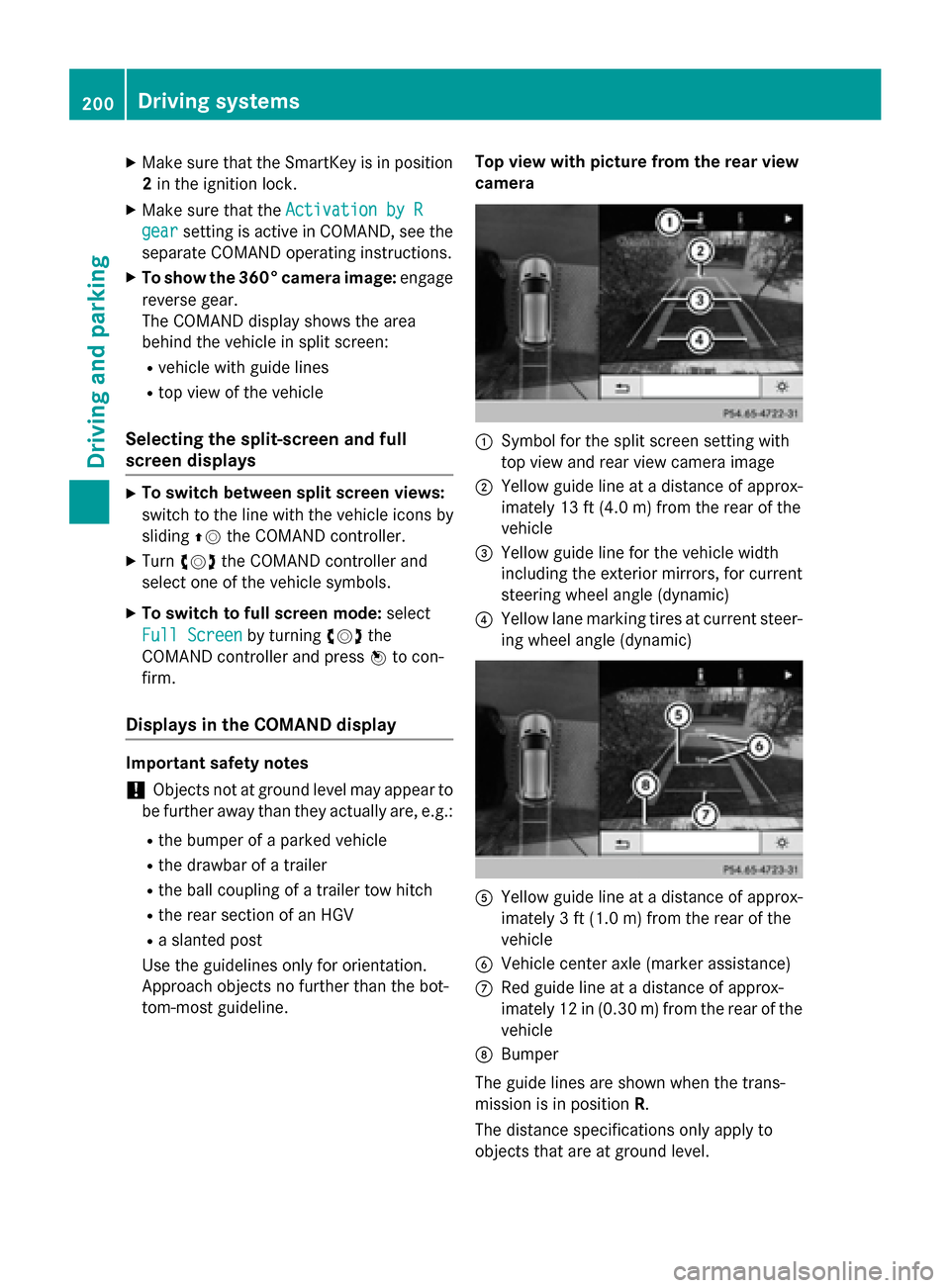
camera 0043
Symbol for the split screen setting with
top view and rear view camera image
0044 Yellow guide line at a distance of approx-
imately 13 ft (4.0 m) from the rear of the
vehicle
0087 Yellow guide line for the vehicle width
including the exterior mirrors, for current
steering wheel angle (dynamic)
0085 Yellow lane marking tires at current steer-
ing wheel angle (dynamic) 0083
Yellow guide line at a distance of approx-
imately 3 ft (1.0 m) from the rear of the
vehicle
0084 Vehicle center axle (marker assistance)
006B Red guide line at a distance of approx-
imately 12 in (0.30 m) from the rear of the
vehicle
006C Bumper
The guide lines are shown when the trans-
mission is in position R.
The distance specifications only apply to
objects that are at ground level. 200
Driving systemsDriving and parking
Page 203 of 386
Top view with picture from the front cam-
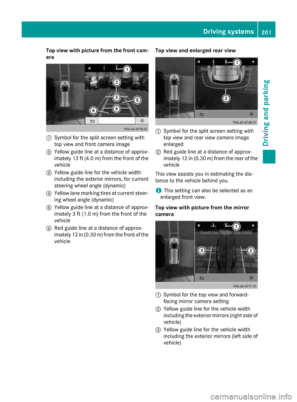
era 0043
Symbol for the split screen setting with
top view and front camera image
0044 Yellow guide line at a distance of approx-
imately 13 ft (4.0 m)from the front of the
vehicle
0087 Yellow guide line for the vehicle width
including the exterior mirrors, for current
steering wheel angle (dynamic)
0085 Yellow lane marking tires at current steer-
ing wheel angle (dynamic)
0083 Yellow guide line at a distance of approx-
imately 3 ft (1.0 m) from the front of the
vehicle
0084 Red guide line at a distance of approx-
imately 12 in (0.30 m) from the front of the
vehicle Top view and enlarged rear view 0043
Symbol for the split screen setting with
top view and rear view camera image
enlarged
0044 Red guide line at a distance of approx-
imately 12 in (0.30 m) from the rear of the
vehicle
This view assists you in estimating the dis-
tance to the vehicle behind you.
i This setting can also be selected as an
enlarged front view.
Top view with picture from the mirror
camera 0043
Symbol for the top view and forward-
facing mirror camera setting
0044 Yellow guide line for the vehicle width
including the exterior mirrors (right side of
vehicle)
0087 Yellow guide line for the vehicle width
including the exterior mirrors (left side of
vehicle) Driving systems
201Driving and parking Z
Page 217 of 386
G
WARNING
If the ball coupling is not correctly installed
and secured, it could come loose while driving and endanger other road users. There is a risk
of an accident and injury.
Install and secure the ball coupling as descri-
bed in the ball coupling manufacturer's instal- lation instructions. Make sure that the ball
coupling is correctly installed and secured
before every journey. Coupling up a trailer
Observe the maximum permissible trailer
dimensions (width and length).
Most U.S. states and all Canadian provinces
require by law: R safety chains between the towing vehicle
and the trailer. The chains should be cross-
wound under the trailer drawbar. They must be fastened to the vehicle's trailer cou-
pling, not to the bumper or the axle.
Leave enough play in the chains to make
tight cornering possible.
R a separate brake system for certain types
of trailer.
R a safety switch for braked trailers. Check
the specific legal requirements applicable
to your state.
If the trailer detaches from the towing vehi-
cle, the safety switch applies the trailer's
brakes.
! Do not connect the trailer's brake system
(if featured) to the hydraulic brake system
of the towing vehicle, as the latter is equip-
ped with an anti-lock brake system. Doing
so will result in a loss of function of the
brake systems of both the vehicle and the
trailer.
i The vehicle's wiring harness features a
connection to the brake indicator lamp. X
Make sure that the automatic transmission
is set to position P.
X Apply the vehicle's parking brake.
X Close all doors and the tailgate.
X Couple up the trailer.
X Establish all electrical connections. Towing a trailer
There are numerous legal requirements con-
cerning the towing of a trailer, e.g. speed
restrictions. Make sure that your car/trailer
combination complies with the local regula-
tions:
R in your place of residence
R in the location to which you are driving
The police and local authorities can provide
reliable information.
Observe the following when towing a trailer:
R To gain driving experience and to become
accustomed to the new handling charac-
teristics, you should practice the following
in a traffic-free location:
- cornering
- stopping
- backing up
R Before driving, check:
- the trailer tow hitch
- the safety switch for braked trailers
- the safety chains
- electrical connections
- the lights
- the wheels
R Adjust the exterior mirrors to provide an
unobstructed view of the rear section of the
trailer.
R If the trailer has electronically controlled
brakes, pull away carefully. Brake manually
using the brake controller and check
whether the brakes function correctly.
R Secure any objects on the trailer to prevent
the cargo from slipping when the vehicle is
in motion. Towing a trailer
215Driving and parking Z
Page 285 of 386
X
Swing the rear seat armrest cover back
down, if necessary.
X To close: raise the rear seat armrest cover.
Swing cup holder 0044back until it engages. Sun visors
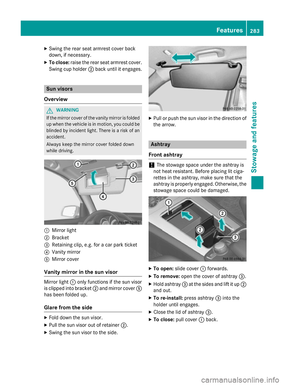
Overview G
WARNING
If the mirror cover of the vanity mirror is folded up when the vehicle is in motion, you could be
blinded by incident light. There is a risk of an
accident.
Always keep the mirror cover folded down
while driving. 0043
Mirror light
0044 Bracket
0087 Retaining clip, e.g. for a car park ticket
0085 Vanity mirror
0083 Mirror cover
Vanity mirror in the sun visor Mirror light
0043only functions if the sun visor
is clipped into bracket 0044and mirror cover 0083
has been folded up.
Glare from the side X
Fold down the sun visor.
X Pull the sun visor out of retainer 0044.
X Swing the sun visor to the side. X
Pull or push the sun visor in the direction of
the arrow. Ashtray
Front ashtray !
The stowage space under the ashtray is
not heat resistant. Before placing lit ciga-
rettes in the ashtray, make sure that the
ashtray is properly engaged. Otherwise, the
stowage space could be damaged. X
To open: slide cover 0043forwards.
X To remove: open the cover of ashtray 0087.
X Hold ashtray 0087at the sides and lift it up 0044
and out.
X To re-install: press ashtray 0087into the
holder until engages.
X Close the lid of ashtray 0087.
X To close: pull cover 0043back. Features
283Stowage and features Z
Page 297 of 386
Triggering the vehicle alarm
With this function, you can trigger the vehi-
cle's panic alarm via text message. An alarm
sounds and the exterior lighting flashes.
Depending on the setting, the panic alarm
lasts five or ten seconds. Afterwards, the
alarm switches off. Garage door opener
General notes The HomeLink
®
garage door opener integra-
ted in the rear-view mirror allows you to oper-
ate up to three different door and gate sys-
tems.
Use the integrated garage door opener only
on garage doors that:
R have safety stop and reverse features and
R meet current U.S. federal safety standards
Once programed, the integrated garage door opener in the rear-view mirror will assume the
function of the garage door system's remote
control. Please also read the operating
instructions for the garage door system.
When programing a garage door opener, park the vehicle outside the garage. Do not run the
engine while programing.
Certain garage door drives are incompatible
with the integrated garage door opener. If you
have difficulty programing the integrated
garage door opener, contact an authorized
Mercedes-Benz Center.
Alternatively, you can call the following tele-
phone assistance services:
R USA: Mercedes-Benz Customer Assistance
Center at 1-800-FOR-MERCedes
R Canada: Customer Service at
1-800-387-0100
R HomeLink ®
hotline 1-800-355-3515 (free
of charge)
More information on HomeLink ®
and/or
compatible products is also available online
at http://www.homelink.com. Notes on the declaration of conformity
(Y
page 26).
USA: FCC ID: CB2HMIHL4
Canada: IC: 279B-HMIHL4
Important safety notes G
WARNING
When you operate or program the garage door with the integrated garage door opener, per-
sons in the range of movement of the garage
door can become trapped or struck by the
garage door. There is a risk of injury.
When using the integrated garage door
opener, always make sure that nobody is
within the range of movement of the garage
door. G
WARNING
Combustion engines emit poisonous exhaust
gases such as carbon monoxide. Inhaling
these exhaust gases leads to poisoning. There is a risk of fatal injury. Therefore never leave
the engine running in enclosed spaces with-
out sufficient ventilation.
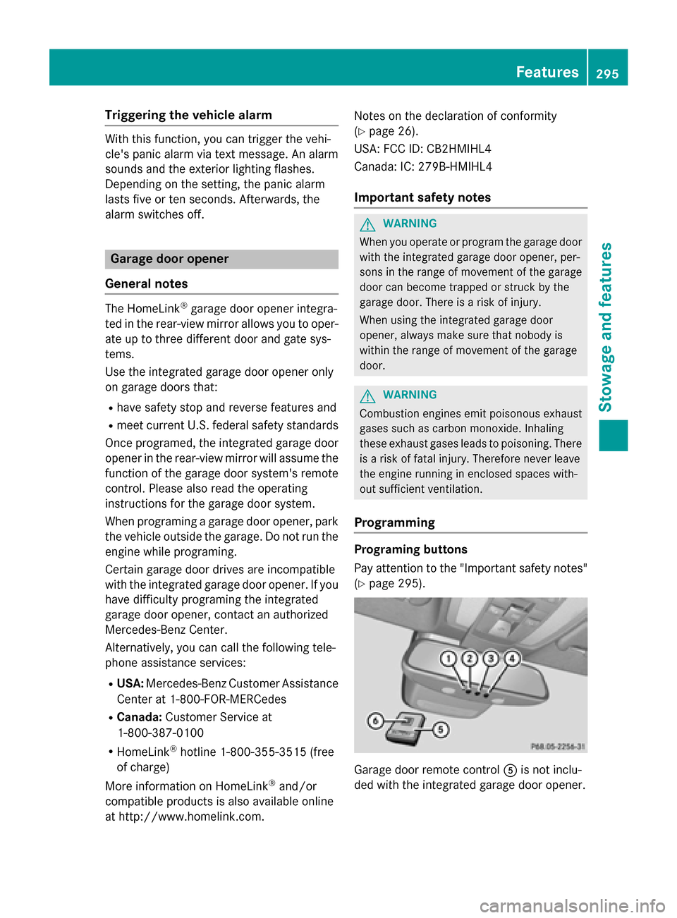
Programming Programing buttons
Pay attention to the "Important safety notes"
(Y page 295). Garage door remote control
0083is not inclu-
ded with the integrated garage door opener. Features
295Stowage an d features Z