MERCEDES-BENZ GLK SUV 2012 Owners Manual
Manufacturer: MERCEDES-BENZ, Model Year: 2012, Model line: GLK SUV, Model: MERCEDES-BENZ GLK SUV 2012Pages: 381, PDF Size: 12.68 MB
Page 221 of 381
G
WARNING
If the ball coupling is not correctly engaged, it
could detach while driving and fall on the road.
There is a risk of an accident and injury.
Engage the ball coupling as described. G
WARNING
If the ball coupling is not correctly engaged,
the trailer can detach. There is a risk of an
accident.
Always engage the ball coupling as described. G
WARNING
If you release the ball coupling or it does not
engage correctly when folding in, it will swing
out. Within pivoting range of the ball coupling,
there is an increased risk of an accident and
injury.
Only release the ball coupling if the pivoting
range is unobstructed. Always make sure that
the ball coupling engages when folding in.
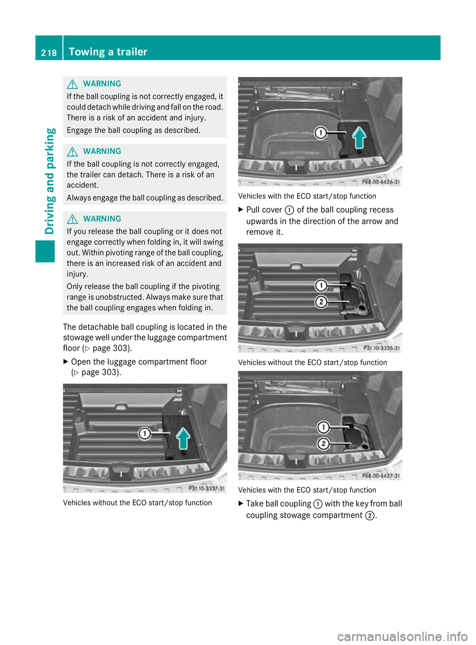
The detachable ball coupling is located in the
stowage well under the luggage compartment
floor (Y page 303).
X Open the luggage compartment floor
(Y page 303). Vehicles without the ECO start/stop function Vehicles with the ECO start/stop function
X
Pull cover :of the ball coupling recess
upwards in the direction of the arrow and
remove it. Vehicles without the ECO start/stop function
Vehicles with the ECO start/stop function
X
Take ball coupling :with the key from ball
coupling stowage compartment ;.218
Towing a trailerDriving and parking
Page 222 of 381
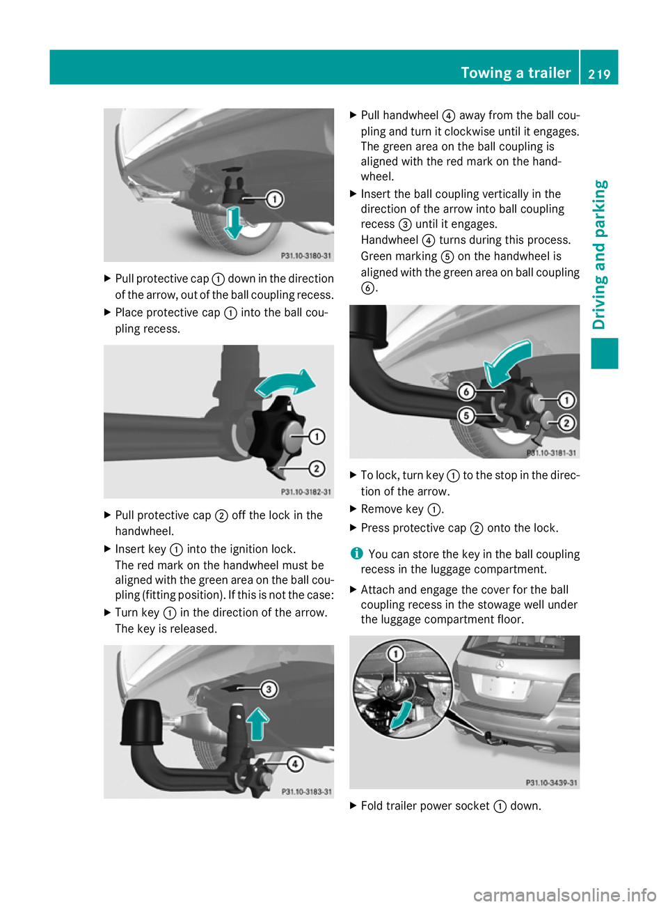
X
Pull protective cap :down in the direction
of the arrow, out of the ball coupling recess.
X Place protective cap :into the ball cou-
pling recess. X
Pull protective cap ;off the lock in the
handwheel.
X Insert key :into the ignition lock.
The red mark on the handwheel must be
aligned with the green area on the ball cou-
pling (fitting position). If this is not the case:
X Turn key :in the direction of the arrow.
The key is released. X
Pull handwheel ?away from the ball cou-
pling and turn it clockwise until it engages.
The green area on the ball coupling is
aligned with the red mark on the hand-
wheel.
X Insert the ball coupling vertically in the
direction of the arrow into ball coupling
recess =until it engages.
Handwheel ?turns during this process.
Green marking Aon the handwheel is
aligned with the green area on ball coupling
B. X
To lock, turn key :to the stop in the direc-
tion of the arrow.
X Remove key :.
X Press protective cap ;onto the lock.
i You can store the key in the ball coupling
recess in the luggage compartment.
X Attach and engage the cover for the ball
coupling recess in the stowage well under
the luggage compartment floor. X
Fold trailer power socket :down. Towing a trailer
219Driving and parking Z
Page 223 of 381
Coupling up a trailer
G
WARNING
If you uncouple a trailer with an engaged over-
run brake, you could trap your hand between
the vehicle and the trailer drawbar. This poses
a risk of injury.
Do not uncouple a trailer with an engaged
overrun brake.
X Make sure that the transmission is in posi-
tion P.
X Engage the parking brake.
X Position the trailer level behind the vehicle.
X Couple up the trailer.
X Establish the electric connection between
the vehicle and the trailer.
X Check that the trailer lighting system is
working. Uncoupling a trailer
G
WARNING
Vehicles with level control:
If you disconnect the trailer cable, the vehicle
is lowered. This can cause you or others to
become trapped between the vehicle body
and tyres, or underneath the vehicle. This
poses a risk of injury.
Make sure that no-one is in the immediate
vicinity of the wheel arch or underneath the
vehicle when disconnecting the trailer cable.
! Do not disconnect a trailer with an
engaged overrun brake. Otherwise, your
vehicle could be damaged by the rebound-
ing of the overrun brake.
X Make sure that the transmission is in posi-
tion P.
X Engage the parking brake.
X Secure the trailer against rolling away.
X Remove the trailer cable and decouple the
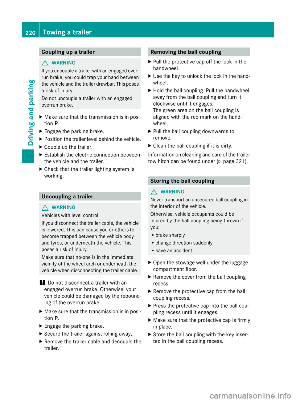
trailer. Removing the ball coupling
X Pull the protective cap off the lock in the
handwheel.
X Use the key to unlock the lock in the hand-
wheel.
X Hold the ball coupling. Pull the handwheel
away from the ball coupling and turn it
clockwise until it engages.
The green area on the ball coupling is
aligned with the red mark on the hand-
wheel.
X Pull the ball coupling downwards to
remove.
X Clean the ball coupling if it is dirty.
Information on cleaning and care of the trailer
tow hitch can be found under (Y page 321). Storing the ball coupling
G
WARNING
Never transport an unsecured ball coupling in
the interior of the vehicle.
Otherwise, vehicle occupants could be
injured by the ball coupling being thrown if
you:
R brake sharply
R change direction suddenly
R have an accident
X Open the stowage well under the luggage
compartment floor.
X Remove the cover from the ball coupling
recess.
X Remove the protective cap from the ball
coupling recess.
X Press the protective cap into the ball cou-
pling recess until it engages.
X Make sure that the protective cap is firmly
in place.
X Store the ball coupling with the key inser-
ted in the ball coupling recess. 220
Towing a trailerDriving and parking
Page 224 of 381
X
Replace the cover of the ball coupling
recess and engage it.
X Fold the trailer power socket upwards. Trailer power supply
When it leaves the factory, your vehicle's
trailer socket is equipped with a permanent
power supply and a power supply that is
switched on via the ignition lock.
The permanent power supply is supplied via
trailer socket pin 9.
The power supply that is switched on via the
ignition lock is supplied via trailer socket pin
10.
! You can connect accessories with a
power rating of up to 240 W to the perma-
nent power supply and with a power rating
of up to 180 W to the power supply that is
switched on via the ignition lock.
The trailer battery may not be charged from
the power supply.
The trailer's permanent power supply is
switched off in the event of low vehicle supply
voltage and after six hours at the latest.
You can find more information about fitting
the trailer electrics at a qualified specialist
workshop.
X To switch the connected power supply
on or off: turn the key in the ignition lock
to position 2or 0respectively. Trailer with 7-pin connector
General notes Trailer with 7-pin connector:
you can con-
nect to the 13-pin socket on the ball coupling
using an adapter or, if necessary, an adapter
cable. Both can be obtained at a qualified
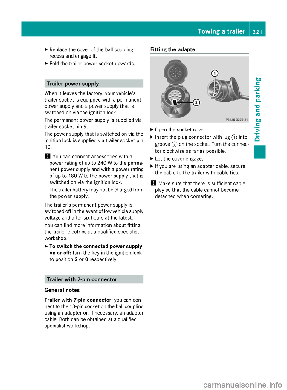
specialist workshop. Fitting the adapter
X
Open the socket cover.
X Insert the plug connector with lug :into
groove ;on the socket. Turn the connec-
tor clockwise as far as possible.
X Let the cover engage.
X If you are using an adapter cable, secure
the cable to the trailer with cable ties.
! Make sure that there is sufficient cable
play so that the cable cannot become
detached when cornering. Towing a trailer
221Driving and parking Z
Page 225 of 381

222
Page 226 of 381
Useful information
............................224
Important safety notes ....................224
Displays and operation (4-button
multifunction steering wheel) .........224
Displays and operation (12-button
multifunction steering wheel) .........227
Display messages ............................. 245
Warning and indicator lamps in the
instrument cluster ............................284 223On-board computer and displays
Page 227 of 381
Useful information
i This Owner's Manual describes all mod-
els, series and optional equipment for your
vehicle that were available at the time of
going to press. National variations are pos-
sible. Note that your vehicle may not be
equipped with all of the functions descri-
bed. This is also the case for systems and
functions relevant to safety.
i Read the information on qualified special-
ist workshops: (Y page 27). Important safety notes
G
WARNING
Only use the on-board computer when road
and traffic conditions permit. You would oth-
erwise be distracted and unable to concen-
trate properly on driving, and could cause an
accident. G
WARNING
No messages will be displayed if either the
instrument cluster or the multifunction dis-
play is inoperative.
As a result, you will not be able to see infor-
mation about your driving conditions, such as
speed, outside temperature, warning and indi-
cator lamps, display messages or system fail-
ures. Driving characteristics may be impaired.
Adjust your driving style and vehicle speed
accordingly.
Contact a qualified specialist workshop
immediately. G
WARNING
The on-board computer only records and dis-
plays malfunctions and warnings from certain
systems. For this reason, you should always
make sure that your vehicle is safe to use. You
could otherwise cause an accident by driving
an unsafe vehicle. G
WARNING
The operating safety of your vehicle could be
impaired if maintenance work is carried out
incorrectly. This could cause you to lose con-
trol of your vehicle and cause an accident.
Moreover, the safety systems may no longer
be able to protect you or others as they are
designed to do.
Always have service work carried out at a
qualified specialist workshop.
Illustration of the instrument cluster
R 4-button multifunction steering wheel, see
(Y page 31)
R 12-button multifunction steering wheel,
see (Y page 33) Displays and operation (4-button mul-
tifunction steering wheel)
Instrument cluster lighting
The lighting in the instrument cluster, in the
displays and the controls in the vehicle inte-
rior can be adjusted using the brightness con-
trol knob.
The brightness control knob is located on the
bottom left of the instrument cluster
(Y page 33).
X Turn the brightness control knob clockwise
or anti-clockwise.
If the light switch is set to Ã,Tor
L, the brightness is dependent upon
the brightness of the ambient light.
i The light sensor in the instrument cluster
automatically controls the brightness of
the multifunction display.
In daylight, the displays in the instrument
cluster are not illuminated. Coolant temperature gauge
The coolant temperature gauge is in the
instrument cluster on the left-hand side. 224
Displays and operation (4-button multifunction steering wheel)On-board computer and displays
Page 228 of 381
Under normal operating conditions and with
the specified coolant level, the coolant tem-
perature may rise to 120 †.
At high outside temperatures and when driv-
ing uphill, the coolant temperature may rise
to the end of the scale. Rev counter
The red band in the rev counter indicates the
engine's overrevving range.
! Do not drive in the overrevving range.
Doing so will damage the engine.
The fuel supply is interrupted to protect the
engine when the red band is reached. Outside temperature display
The outside temperature display is in the
instrument cluster (Y page 31).G
WARNING
At temperatures just above freezing point, the
street may be icy, especially in wooded areas
or on bridges. If you do not adapt your driving
style to the conditions, the vehicle could skid.
For this reason, adapt your driving style and
speed to the weather conditions.
Changes in the outside temperature are dis-
played after a short delay. Operating the on-board computer
The on-board computer is activated as soon
as you turn the key to position 1in the ignition
lock. You can use the on-board computer to
call up information relating to your vehicle
and to make and adjust settings.
i You can have certain functions set at a
qualified specialist workshop, e.g. a
Mercedes-Benz Service Centre. Examples:
R
automatic door locking
R speed limit for winter tyres
You can obtain information about this at
any Mercedes-Benz Service Centre.
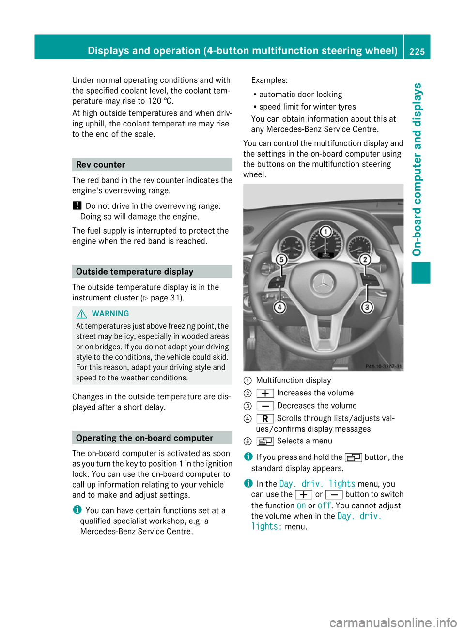
You can control the multifunction display and
the settings in the on-board computer using
the buttons on the multifunction steering
wheel. :
Multifunction display
; W Increases the volume
= X Decreases the volume
? C Scrolls through lists/adjusts val-
ues/confirms display messages
A V Selects a menu
i If you press and hold the Vbutton, the
standard display appears.
i In the Day. driv. lights Day. driv. lights menu, you
can use the WorX button to switch
the function on
onoroff
off. You cannot adjust
the volume when in the Day. driv.
Day. driv.
lights:
lights: menu. Displays and operation (4-button multifunction steering wheel)
225On-board computer and displays Z
Page 229 of 381
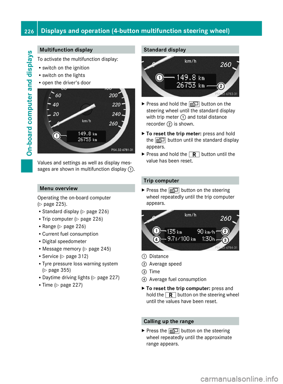
Multifunction display
To activate the multifunction display:
R switch on the ignition
R switch on the lights
R open the driver's door Values and settings as well as display mes-
sages are shown in multifunction display :.Menu overview
Operating the on-board computer
(Y page 225).
R Standard display (Y page 226)
R Trip computer (Y page 226)
R Range (Y page 226)
R Current fuel consumption
R Digital speedometer
R Message memory (Y page 245)
R Service (Y page 312)
R Tyre pressure loss warning system
(Y page 355)
R Daytime driving lights (Y page 227)
R Time (Y page 227) Standard display
X
Press and hold the Vbutton on the
steering wheel until the standard display
with trip meter :and total distance
recorder ;is shown.
X To reset the trip meter: press and hold
the V button until the standard display
appears.
X Press and hold the Cbutton until the
value has been reset. Trip computer
X Press the Vbutton on the steering
wheel repeatedly until the trip computer
appears. :
Distance
; Average speed
= Time
? Average fuel consumption
X To reset the trip computer: press and
hold the Cbutton on the steering wheel
until the values have been reset. Calling up the range
X Press the Vbutton on the steering
wheel repeatedly until the approximate
range appears. 226
Displays and operation (4-button multifunction steering wheel)On-board computer and displays
Page 230 of 381
The approximate range which can be covered
depends on the fuel level and your current
driving style. If there is only a small amount
of fuel left in the fuel tank, the display shows
a vehicle being refuelled Cinstead of the
range. Switching the daytime driving lights
on/off
If you have activated the Day. driv.
Day. driv.
lights: lights: function and the light switch is in the
à position, the daytime driving lights are
switched on automatically when the engine is
running. When it is dark, the side lamps and
the dipped-beam headlamps are switched on
automatically.
On vehicles with daytime driving lamps, the
factory setting is on
on.
If you want to change the setting for the Day. Day.
driv. lights:
driv. lights: function, you have to turn
the key in the ignition lock to position 1.
X Press the Vbutton on the steering
wheel repeatedly until the Day. driv.
Day. driv.
lights:
lights: menu appears.
You will see the selected setting: on
onor
off
off.
X Press the WorX button to change
the setting. Time/date
i Depending on your vehicle's equipment,
the time can be set using the on-board
computer or the audio system/COMAND,
see the separate operating instructions.
X Press the Vbutton on the steering
wheel repeatedly until the "Time/date"
menu appears.
X To set: use the Cbutton to select the
display you want to change: hour, minutes,
day, month, year. X
Press WorX to set the selected dis-
play.
X To save: press the Cbutton.
The next display is selected. Displays and operation (12-button
multifunction steering wheel)
Coolant temperature gauge
The coolant temperature gauge is in the
instrument cluster on the left-hand side.
Under normal operating conditions and with
the specified coolant level, the coolant tem-
perature may rise to 120 †.
At high outside temperatures and when driv-
ing uphill, the coolant temperature may rise
to the end of the scale. Rev counter
The red band in the rev counter indicates the
engine's overrevving range.
! Do not drive in the overrevving range.
Doing so will damage the engine.
The fuel supply is interrupted to protect the
engine when the red band is reached. Outside temperature display
The outside temperature display is in the mul-
tifunction display (Y page 229). G
WARNING
At temperatures just above freezing point, the
street may be icy, especially in wooded areas
or on bridges. If you do not adapt your driving
style to the conditions, the vehicle could skid.
For this reason, adapt your driving style and
speed to the weather conditions.
Changes in the outside temperature are dis-
played after a short delay. Displays and operation (12-button multifunction steering wheel)
227On-board computer and displays Z