service reset MERCEDES-BENZ GLK SUV 2012 Owners Manual
[x] Cancel search | Manufacturer: MERCEDES-BENZ, Model Year: 2012, Model line: GLK SUV, Model: MERCEDES-BENZ GLK SUV 2012Pages: 381, PDF Size: 12.68 MB
Page 8 of 381
Air vents
Glove compartment .......................142
Important safety notes ..................141
Rear ............................................... 143
Setting ........................................... 141
Setting the centre air vents ...........142
Setting the side air vents ...............142
Alarm system
see ATA (Anti-Theft Alarm system)
Anti-glare film .................................... 310
Anti-lock Braking System see ABS (Anti-lock Braking System)
Anti-Theft Alarm system
see ATA (Anti-Theft Alarm system)
Approach/departure angle ..............172
Aquaplaning ....................................... 168
Ashtray ............................................... 306
ASSYST PLUS Displaying a service message ........312
Hiding a service message ..............312
Notes ............................................. 312
Resetting the service interval dis-
pla y................................................ 312
Service message ............................ 312
Special service requirements ......... 313
ATA (Anti-Theft Alarm system)
Activating/deactivating ...................72
Function .......................................... .72
Interior motion sensor .....................73
Switching off the alarm ....................72
Tow-away protection ........................ 72
ATTENTION ASSIST
Activating/deactivating .................237
Display message (12-button mul-
tifunction steering wheel) ..............271
Function/notes ............................. 201
Audio DVD (12-button multifunc-
tion steering wheel) ..........................233
Audio menu (on-board computer,
12-button multifunction steering
wheel) ................................................ .233
Audio menu (on-board computer) ....233
Authorised workshop see Qualified specialist workshop AUTO lights
Display message (12-button mul-
tifunction steering wheel) ..............263
Display message (4-button multi-
function steering wheel) ................260
see Lights
Automatic engine start (ECO start/
stop function) .................................... 152
Automatic engine switch-off (ECO
start/stop function) ..........................151
Automatic headlamp mode ..............111
Automatic transmission Accelerator pedal position .............157
Automatic drive program ...............159
Changing gea r............................... 157
DIRECT SELECT lever .....................155
Display message (4-button multi-
function steering wheel) ................278
Drive position (ECO start/stop
function) ........................................ 157
Driving tips .................................... 157
Emergency running mode ..............161
Engaging drive position .................. 157
Engaging neutral ............................ 157
Engaging park position automati-
call y............................................... 156
Engaging reverse gear ...................156
Engaging the park position ............156
Kickdown ....................................... 158
Manual drive program ....................160
Neutral (ECO start/stop function) .156
Problem (fault) ............................... 161
Program selector button ................158
Pulling away ................................... 149
Shift ranges ................................... 159
Starting the engine ........................148
Steering wheel gearshift paddle s... 159
Trailer towing ................................. 158
Transmission position displa y........ 156
Transmission positions ..................157
Automatic transmission emer-
gency running mode .........................161
Automatic transmissions Display message (12-button mul-
tifunction steering wheel) ..............279 Index
5
Page 19 of 381
MP3
Operating ...................................... .233
see Separate operating instructions
Multifunction display
4-button multifunction steering
wheel ............................................. 226
Permanent display (12-button
multifunction steering wheel) ........239
Multi-function display
12-button multifunction steering
wheel ............................................. 229N
Navigation Menu (on-board computer) ............232
On-board computer (12-button
multifunction steering wheel) ........232
see separate operating instructions
NECK-PRO head restraints
Operation ........................................ .49
Resetting after being triggered ........49
NECK-PRO luxury head restraints
Operation ........................................ .49
Resetting after being triggered ........49
Notes on running in a new vehicle ..146 O
Occupant safety Children in the vehicle .....................54
Important safety notes ....................42
Odometer
4-button multifunction steering
wheel ............................................. 226
see Total distance recorder
see Trip meter
Off-road drive program .....................215
Off-road driving Checklist after driving off-road ......171
Checklist before driving off-road .... 171
General information .......................170
Important safety notes ..................170
Travelling uphill .............................. 172
Off-road lights ................................... .115
Off-road system 4MATIC .......................................... 213
DSR ............................................... 213Off-road ABS
.................................... 66
Off-road drive program ..................215
Off-road ESP ®
.................................. 69
Oil
see Engine oil
On-board computer
Light submenu ............................... 239
Operating the TV ............................ 234
On-board computer (12-button
multifunction steering wheel)
Assist menu ................................... 236
Audio menu ................................... 233
Convenience submenu ..................243
Important safety notes ..................224
Instrument cluster submenu ..........238
Lights submenu ............................. 239
Menu overview .............................. 230
Navigation menu ............................ 232
Operating ...................................... .228
Operating the video DVD ...............234
Range ............................................ 231
Service menu ................................. 238
Standard display submenu ............230
Telephone menu ............................ 234
Trip menu ...................................... 230
On-board computer (12-button
multifunction steering wheel)
Displaying service messages .........312
Display messages ..........................245
Heating submenu ........................... 242
Message memory .......................... 246
Vehicle submenu ........................... 241
On-board computer (12-button
multifunction steering wheel)Set-
tings menu ......................................... 238
On-board computer (12-button
multifunction steering wheel) sub-
menu
Factory setting ............................... 244
On-board computer (4-button mul-
tifunction steering wheel)
Important safety notes ..................224
Menu overview .............................. 226
Switching daytime driving lights
on/off ............................................ 22716
Index
Page 20 of 381
On-board computer (4-button mul-
tifunction steering wheel)
Displaying service messages .........312
Display messages ..........................245
Individual vehicle settings ..............225
Message memory .......................... 245
Operating ...................................... .225
Range ............................................ 226
Standard displa y............................ 226
Time/date ..................................... 227
Trip computer ................................ 226
Opening and closing the side trim
panels ................................................. 121
Operating safety Diagnostics connection ...................26
Operating system
see On-board computer
Outside temperature
Display (12-button multifunction
steering wheel) .............................. 227
Display (4-button multifunction
steering wheel) .............................. 225
Overhead control panel ......................39
Override feature Rear side windows ...........................64 P
Paint code .......................................... 364
Paintwork (cleaning instructions) ...319
Panic alarm .......................................... 42
Panorama sliding sunroof Important safety information ...........92
Opening/closing .............................. 92
Opening/closing the roller sun-
blind ................................................. 93
Problem (malfunction) .....................94
Rain closing feature .........................92
Resetting ......................................... 93
Parking ............................................... 164
Important safety notes ..................164
Parking brake ................................ 165
Position of exterior mirror, front-
passenger side ............................... 105
Reversing camera ..........................196
see PARKTRONIC Parking aid
Active Parking Assist .....................192
see Exterior mirrors
see PARKTRONIC
Parking brake .................................... 165
Display message (12-button mul-
tifunction steering wheel) ..............253
Display message (4-button multi-
function steering wheel) ................248
Notes/function .............................. 165
Warning lamp ................................. 291
Parking lamp
Display message (12-button mul-
tifunction steering wheel) ..............262
Display message (4-button multi-
function steering wheel) ................259
Parking lamps
Changing bulbs .............................. 120
Switching on/off ........................... 112
PARKTRONIC
Deactivating/activating .................190
Driving system ............................... 188
Function/notes ............................. 188
Important safety notes ..................188
Problem (fault) ............................... 192
Sensor range ................................. 188
Trailer towing ................................. 191
Warning displa y............................. 189
PASSENGER AIRBAG OFF warning
lamp ...................................................... 56
Petrol .................................................. 366
Plastic trim (cleaning instructions) .322
Power windows see Side windows
PRE-SAFE ®
(preventative occupant
protection) Display message (12-button mul-
tifunction steering wheel) ..............254
Display message (4-button multi-
function steering wheel) ................249
PRE-SAFE ®
(preventive occupant
safety system) Operation ........................................ .48
PRE-SAFE ®
Brake
Activating/deactivating .................237
Display message (12-button mul-
tifunction steering wheel) ..............255 Index
17
Page 30 of 381
Do not connect any equipment to a diagnos-
tics connection. G
WARNING
Loose equipment or cables hanging from a
device which are connected to a diagnostic
connection could impede pedal clearance.
The equipment or cables could get caught
between the pedals when driving and braking
suddenly. This could impair the function of the
pedals. There is a risk of accident.
Do not attach any equipment or cables in the
driver's footwell.
! If the engine is switched off and equip-
ment on the diagnostics connection is
used, the starter battery may discharge.
The diagnostics connection is only intended
for the connection of diagnostic equipment at
a qualified specialist workshop.
Connecting equipment to the diagnostics
connection can lead to emissions monitoring
information being reset, for example. This
may lead to the vehicle failing to meet the
requirements of the next emissions test dur-
ing the main inspection. Qualified specialist workshop
A qualified specialist workshop has the nec-
essary special skills, tools and qualifications
to correctly carry out any necessary work on
your vehicle. This particularly applies to work
relevant to safety.
Observe the notes in the Service Booklet.
Always have the following work carried out at
a qualified specialist workshop:
R work relevant to safety
R service and maintenance work
R repair work
R modifications, installations and conver-
sions
R work on electronic components
Mercedes-Benz recommends that you use a
Mercedes-Benz Service Centre. Vehicle registration
Mercedes-Benz may ask its Service Centres
to carry out technical inspections on certain
vehicles. The quality or safety of the vehicle
is improved as a result of the inspection.
Mercedes-Benz can only inform you about
vehicle checks if it has your registration data.
It is possible that your vehicle has not yet
been registered in your name in the following
cases:
R if your vehicle was not purchased at an
authorised specialist dealer.
R if your vehicle has not yet been examined
at a Mercedes-Benz Service Centre.
It is advisable to register your vehicle with a
Mercedes-Benz Service Centre.
Inform Mercedes-Benz as soon as possible
about any change in address or vehicle own-
ership. Correct use
G
WARNING
Various warning stickers are affixed to your
vehicle. Their purpose is to draw your atten-
tion, and the attention of others, to various
dangers. Therefore, do not remove any warn-
ing stickers unless the sticker clearly states
that you may do so.
If you remove the warning stickers, you or
others could be injured by failing to recognise
certain dangers.
Observe the following information when driv-
ing your vehicle:
R the safety notes in this manual
R the "Technical data" section in this manual
R traffic rules and regulations
R laws and safety standards pertaining to
motor vehicles Introduction
27 Z
Page 52 of 381
!
Make sure that there are no objects in the
footwell or behind the seats when moving
the seat back. There is a risk that the seats
and/or the objects could be damaged.
More information about seat belt adjustment,
a convenience function integrated into PRE-
SAFE ®
, can be found in the "Seat belt adjust-
ment" section (Y page 51). NECK-PRO head restraints/NECK-
PRO luxury head restraints
NECK-PRO head restraints/NECK-PRO luxury
head restraints increase protection of the
driver's and front-passenger's head and
neck. In the event of a rear collision of a cer-
tain severity, the NECK-PRO head restraints/
NECK-PRO luxury head restraints on the driv-
er's and front-passenger seats are moved for-
wards and upwards. This provides better
head support. G
WARNING
Only use head restraint covers which have
been tested and approved by Mercedes-Benz
for your vehicle model.
The use of non-approved head restraint cov-
ers may prevent NECK-PRO head restraints/
NECK-PRO luxury head restraints from trig-
gering properly. The NECK-PRO head
restraints/NECK-PRO luxury head restraints
can therefore not provide the intended pro-
tection.
Consult a Mercedes-Benz Service Centre
regarding availability.
If the NECK-PRO head restraints/NECK-PRO
luxury head restraints have been triggered in
an accident, reset the NECK-PRO head
restraints/NECK-PRO luxury head restraints
on the driver's and front-passenger seats
(Y page 49). Otherwise, the additional pro-
tection will not be available in the event of
another rear-end collision. NECK-PRO head
restraints/NECK-PRO luxury head restraints
that have been triggered are moved forwards
and can no longer be adjusted. Resetting a triggered NECK-PRO head
restraint/NECK-PRO luxury head
restraint
Important safety notes Mercedes-Benz recommends that you have
NECK-PRO head restraints/NECK-PRO luxury
head restraints checked at a qualified spe-
cialist workshop, e.g. a Mercedes-Benz
Service Centre, if your vehicle is involved in a
rear-end collision.
NECK-PRO head restraints
i
Resetting the NECK-PRO head restraints
requires a lot of strength. If you have diffi-
culty resetting the NECK-PRO head
restraints, have this work carried out at a
qualified specialist workshop, e.g. a
Mercedes-Benz Service Centre. X
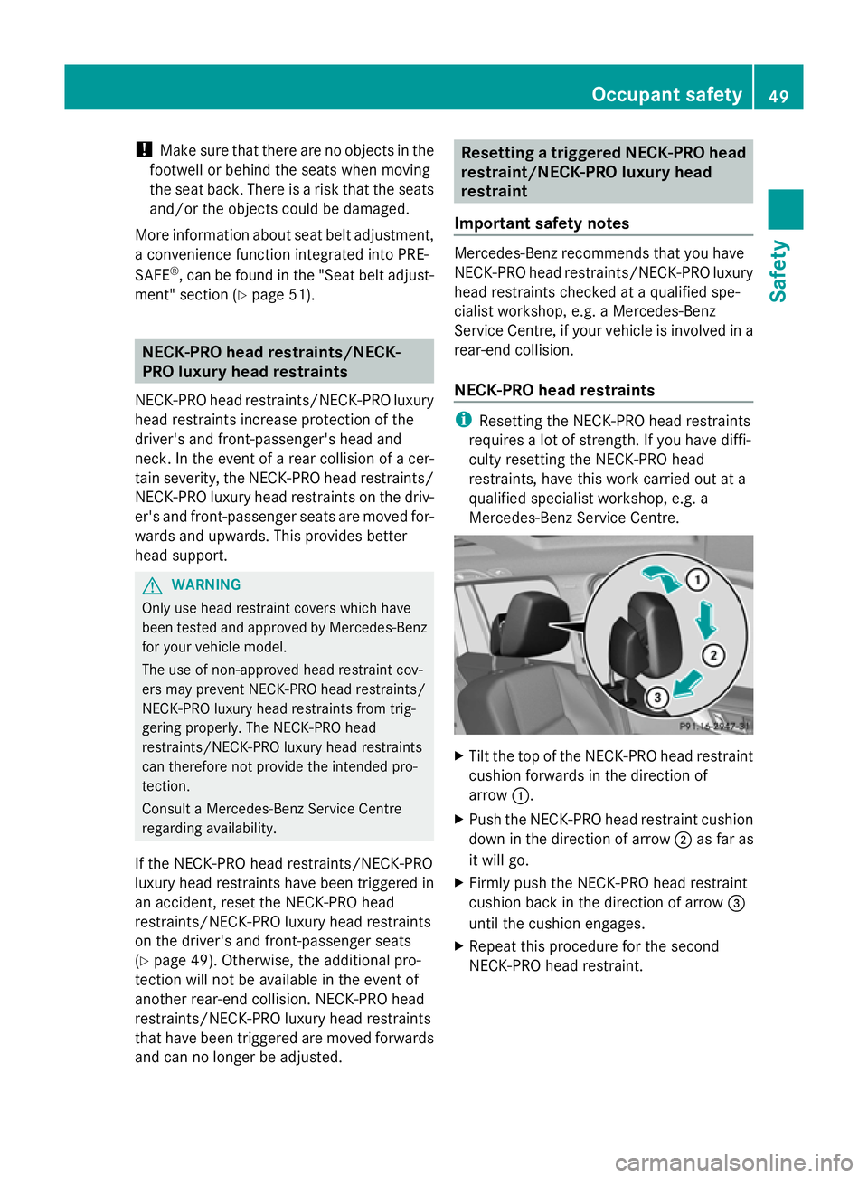
Tilt the top of the NECK-PRO head restraint
cushion forwards in the direction of
arrow :.
X Push the NECK-PRO head restraint cushion
down in the direction of arrow ;as far as
it will go.
X Firmly push the NECK-PRO head restraint
cushion back in the direction of arrow =
until the cushion engages.
X Repeat this procedure for the second
NECK-PRO head restraint. Occupant safety
49Safety Z
Page 53 of 381
NECK-PRO luxury head restraints
i
If you have difficulty resetting the NECK-
PRO luxury head restraints, have this work
carried out at a qualified specialist work-
shop, e.g. a Mercedes-Benz Service
Centre. X
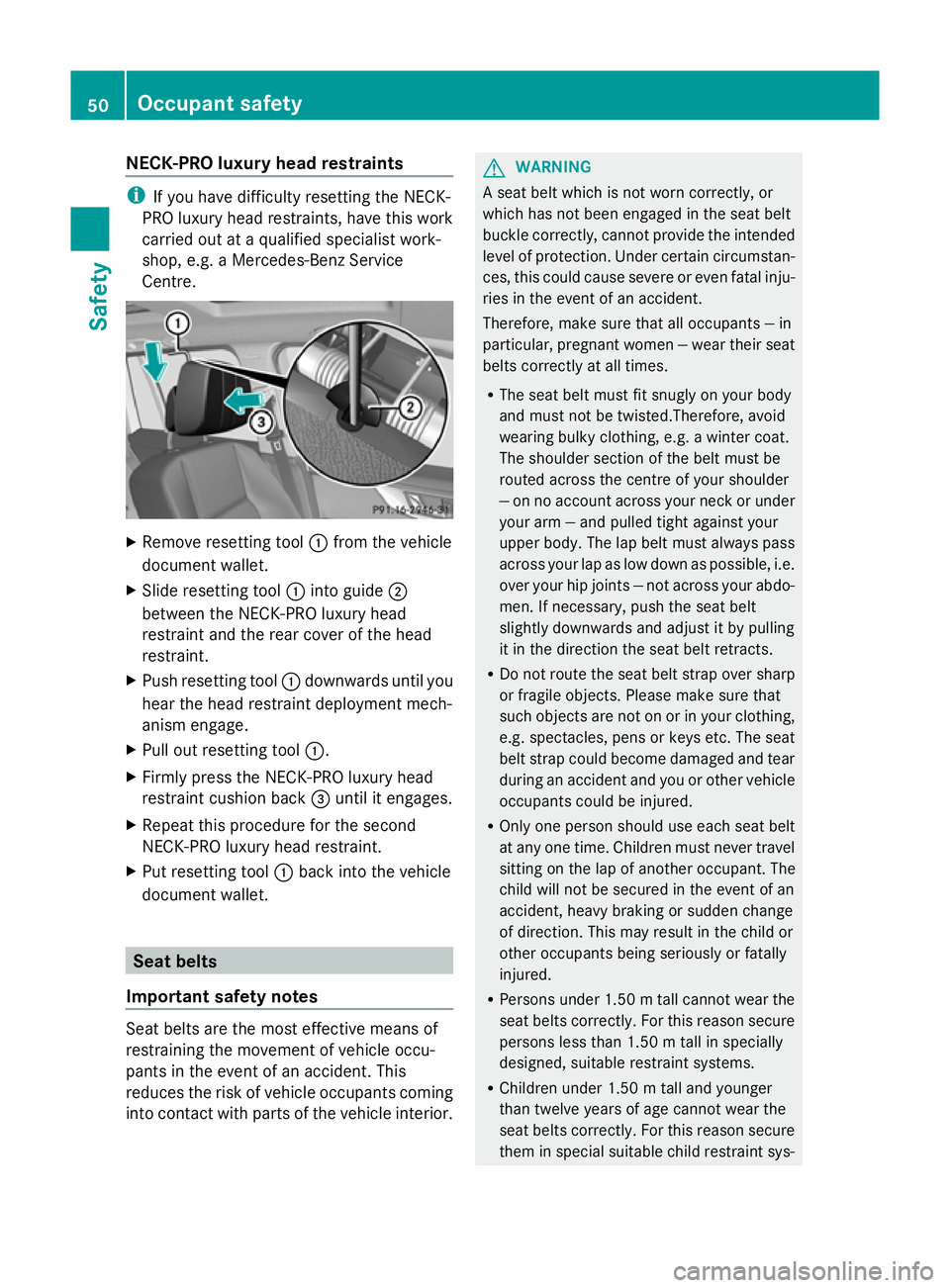
Remove resetting tool :from the vehicle
document wallet.
X Slide resetting tool :into guide ;
between the NECK-PRO luxury head
restraint and the rear cover of the head
restraint.
X Push resetting tool :downwards until you
hear the head restraint deployment mech-
anism engage.
X Pull out resetting tool :.
X Firmly press the NECK-PRO luxury head
restraint cushion back =until it engages.
X Repeat this procedure for the second
NECK-PRO luxury head restraint.
X Put resetting tool :back into the vehicle
document wallet. Seat belts
Important safety notes Seat belts are the most effective means of
restraining the movement of vehicle occu-
pants in the event of an accident. This
reduces the risk of vehicle occupants coming
into contact with parts of the vehicle interior. G
WARNING
A seat belt which is not worn correctly, or
which has not been engaged in the seat belt
buckle correctly, cannot provide the intended
level of protection. Under certain circumstan-
ces, this could cause severe or even fatal inju-
ries in the event of an accident.
Therefore, make sure that all occupants — in
particular, pregnant women — wear their seat
belts correctly at all times.
R The seat belt must fit snugly on your body
and must not be twisted.Therefore, avoid
wearing bulky clothing, e.g. a winter coat.
The shoulder section of the belt must be
routed across the centre of your shoulder
— on no account across your neck or under
your arm — and pulled tight against your
upper body. The lap belt must always pass
across your lap as low down as possible, i.e.
over your hip joints — not across your abdo-
men. If necessary, push the seat belt
slightly downwards and adjust it by pulling
it in the direction the seat belt retracts.
R Do not route the seat belt strap over sharp
or fragile objects. Please make sure that
such objects are not on or in your clothing,
e.g. spectacles, pens or keys etc. The seat
belt strap could become damaged and tear
during an accident and you or other vehicle
occupants could be injured.
R Only one person should use each seat belt
at any one time. Children must never travel
sitting on the lap of another occupant. The
child will not be secured in the event of an
accident, heavy braking or sudden change
of direction. This may result in the child or
other occupants being seriously or fatally
injured.
R Persons under 1.50 mtall cannot wear the
seat belts correctly. For this reason secure
persons less than 1.50 m tall in specially
designed, suitable restraint systems.
R Children under 1.50 m tall and younger
than twelve years of age cannot wear the
seat belts correctly. For this reason secure
them in special suitable child restraint sys- 50
Occupant safetySafety
Page 229 of 381
Multifunction display
To activate the multifunction display:
R switch on the ignition
R switch on the lights
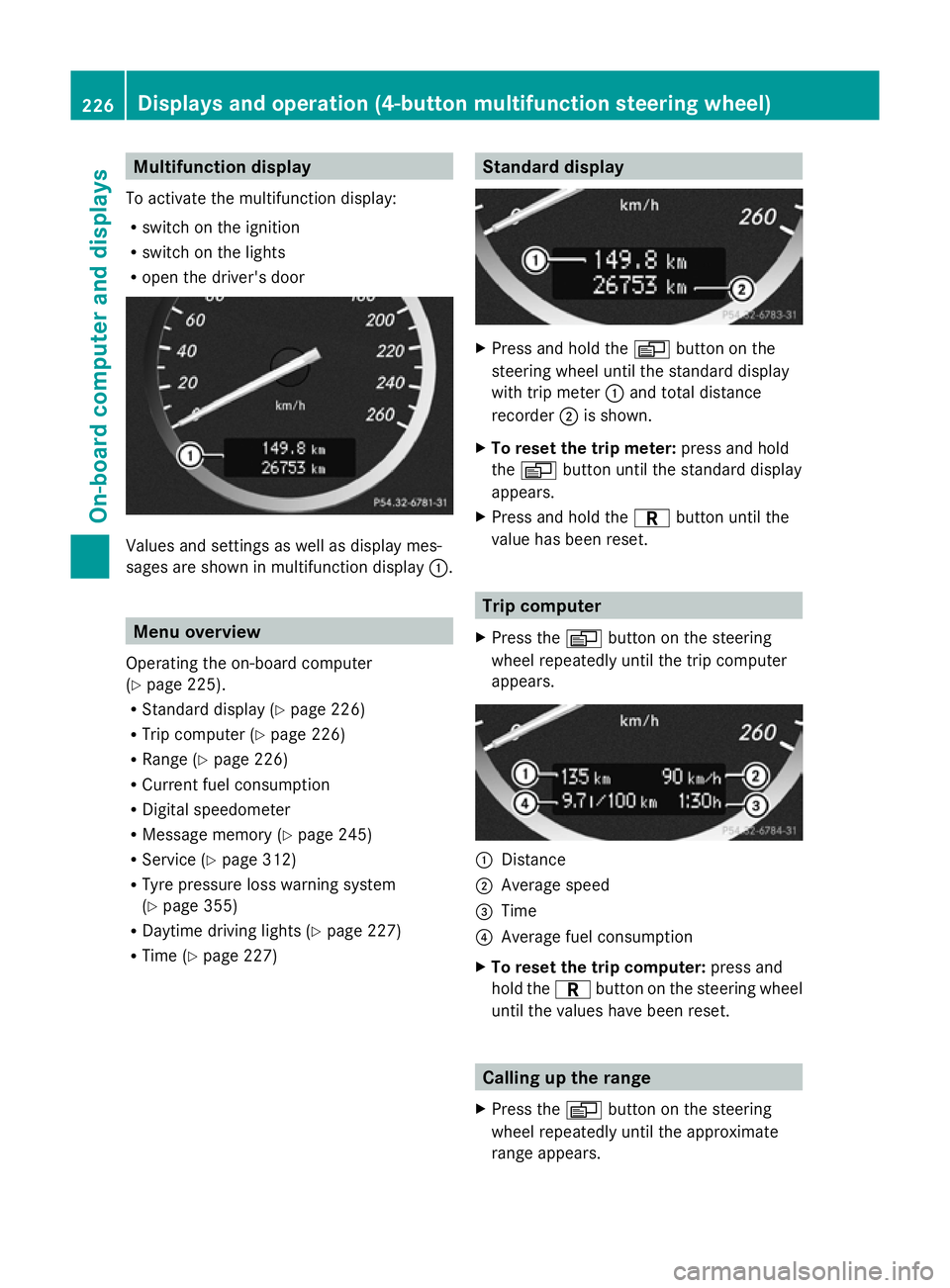
R open the driver's door Values and settings as well as display mes-
sages are shown in multifunction display :.Menu overview
Operating the on-board computer
(Y page 225).
R Standard display (Y page 226)
R Trip computer (Y page 226)
R Range (Y page 226)
R Current fuel consumption
R Digital speedometer
R Message memory (Y page 245)
R Service (Y page 312)
R Tyre pressure loss warning system
(Y page 355)
R Daytime driving lights (Y page 227)
R Time (Y page 227) Standard display
X
Press and hold the Vbutton on the
steering wheel until the standard display
with trip meter :and total distance
recorder ;is shown.
X To reset the trip meter: press and hold
the V button until the standard display
appears.
X Press and hold the Cbutton until the
value has been reset. Trip computer
X Press the Vbutton on the steering
wheel repeatedly until the trip computer
appears. :
Distance
; Average speed
= Time
? Average fuel consumption
X To reset the trip computer: press and
hold the Cbutton on the steering wheel
until the values have been reset. Calling up the range
X Press the Vbutton on the steering
wheel repeatedly until the approximate
range appears. 226
Displays and operation (4-button multifunction steering wheel)On-board computer and displays
Page 315 of 381
Useful information
i This Owner's Manual describes all mod-
els, series and optional equipment for your
vehicle that were available at the time of
going to press. National variations are pos-
sible. Note that your vehicle may not be
equipped with all of the functions descri-
bed. This is also the case for systems and
functions relevant to safety.
i Read the information on qualified special-
ist workshops: (Y page 27). Service
ASSYST PLUS
Service messages The ASSYST PLUS service interval display
informs you of the next service due date.
Information on the type of service and service
intervals (see separate Service Booklet).
You can obtain further information from a
Mercedes-Benz Service Centre.
i The ASSYST PLUS service interval display
does not show any information on the
engine oil level. Observe the notes on the
engine oil level (Y page 315).
The multifunction display shows a service
message for a few seconds, e.g.:
Next service A in .. days
Next service A in .. days
Service A due Service A due
Service A overdue by ... days Service A overdue by ... days
The letter indicates which service is due. A A
stands for a minor service and B
Bfor a major
service. A number or another letter may be
displayed after the letter. This figure indicates
any necessary additional maintenance work
to be performed.
If you notify a qualified specialist workshop of
this display, you will receive a statement on
the associated costs.
The ASSYST PLUS service interval display
does not take into account any periods of time during which the battery is disconnec-
ted.
Maintaining the time-dependent service
schedule:
X
Note down the service due date displayed
in the multifunction display before discon-
necting the battery.
or
X After reconnecting the battery, subtract
the battery disconnection periods from the
service date shown on the display.
Hiding a service message X
4-button multifunction steering wheel:
press the Cbutton.
X 12-button multifunction steering
wheel: press%ora.
Displaying service messages X
Switch the ignition on.
4-button multifunction steering wheel
X Use the Vbutton to select the
Service menu.
The service due date appears in the multi-
function display.
12-button multifunction steering wheel
X Press the toru button to select the
Serv.
Serv. menu.
X Press the sorr button to select the
ASSYST PLUS ASSYST PLUS submenu and confirm by
pressing the abutton.
The service due date appears in the multi-
function display.
Information about Service Resetting the ASSYST PLUS service inter-
val display
! If the ASSYST PLUS service interval dis-
play has been inadvertently reset, this set-
ting can be corrected at a qualified special-
ist workshop. 312
ServiceMaintenance and care
Page 316 of 381
Have service work carried out as described
in the Service Booklet. This may otherwise
lead to increased wear and damage to the
major assemblies or the vehicle.
A qualified specialist workshop, e.g. a
Mercedes-Benz Service Centre, will reset the
ASSYST PLUS service interval display after
the service work has been carried out. You
can also obtain further information on main-
tenance work, for example.
Special service requirements
Arduous operating conditions or increased
loads on the vehicle will require some service
work to be performed more often than for a
vehicle in normal use. Such arduous condi-
tions include regular city driving with frequent
intermediate stops and use in mountainous
terrain or on poor road surfaces.
For example, if the vehicle is used under ardu-
ous operating conditions, have air filters,
engine oil and oil filters changed frequently
and check the wheels often. Further informa-
tion can be obtained at a qualified specialist
workshop, e.g. a Mercedes-Benz Service
Centre.
Driving abroad
An extensive Mercedes-Benz Service network
is also available in other countries. The
Service Hotline's current telephone numbers
for use when you are abroad are to be found
in the "Mercedes-Benz Service24h" section
of the Service Booklet. AdBlue
®
service display
i For BlueTEC vehicles only.
To function properly, BlueTEC exhaust gas
aftertreatment must be operated with the
reducing agent AdBlue ®
. AdBlue ®
is topped
up as part of the service. Under normal oper-
ating conditions, a full tank of AdBlue ®
should
last until the next service due date.
Depending on how and where the vehicle is
used, there may be an increase in the AdBlue
®
consumption, resulting in the next
service due date being brought forward.
Certain display messages show that
AdBlue ®
must be topped up, e.g.
Refill AdBlue at workshop See Own‐
Refill AdBlue at workshop See Own‐
er's Manual er's Manual
Refill AdBlue at workshop No start Refill AdBlue at workshop No start
in .. km in .. km
A warning tone also sounds.
You can no longer start the engine when the
AdBlue ®
supply has been used up.
R 4-button multifunction steering wheel
(Y page 266)
R 12-button multifunction steering wheel
(Y page 269)
! Have the AdBlue ®
tank topped up at a
qualified specialist workshop only. The
vehicle may otherwise be damaged or
soiled.
Before taking a trip with your vehicle outside
Europe, have the AdBlue ®
supply checked at
a qualified specialist workshop. If necessary,
have AdBlue ®
topped up. Before a longer stay
outside of Europe, consult a qualified special-
ist workshop.
Observe the notes on AdBlue ®
(Y page 368).
You can obtain further information about
BlueTEC exhaust gas aftertreatment and
AdBlue ®
from any Mercedes-Benz Service
Centre. Engine compartment
Bonnet
Opening the bonnet G
WARNING
Do not pull the release lever while the vehicle
is in motion. If you do so, the bonnet may open
up and block your view. Engine compartment
313Maintenance and care Z
Page 342 of 381
!
You should have all work involving the
battery carried out at a qualified specialist
workshop. In the exceptional case that it is
necessary for you to disconnect the battery
yourself, make sure that:
R you switch off the engine and remove the
key. On vehicles with KEYLESS-GO,
ensure that the ignition is switched off.
Check that all the indicator lamps in the
instrument cluster are off. Otherwise,
electronic components, such as the
alternator, may be damaged.
R you first remove the negative terminal
clamp and then the positive terminal
clamp. Never swap the terminal clamps.
Otherwise, the vehicle's electronic sys-
tem may be damaged.
R in vehicles with automatic transmission,
the transmission is locked in position P
after disconnecting the battery. The vehi-
cle is secured against rolling away. You
can then no longer move the vehicle.
The battery and the cover of the positive
terminal clamp must be fitted securely dur-
ing operation.
In order for the battery to achieve the maxi-
mum possible service life, it must always be
sufficiently charged.
Have the battery charge checked more fre-
quently if you use the vehicle mainly for short
trips or if you leave it standing idle for a
lengthy period. Consult a qualified specialist
workshop if you wish to leave your vehicle
parked up for a long period of time.
Like other batteries, the vehicle battery may
discharge over time if you do not use the
vehicle. In such cases, have the battery dis-
connected at a qualified specialist workshop.
You can also charge the battery with a
charger recommended by Mercedes-Benz.
For more information, please contact a quali-
fied specialist workshop.
i When you park the vehicle, remove the
key if you do not require any electrical con-
sumers. The vehicle will then use very little
energy, thus conserving battery power. i
If the power supply has been interrupted,
e.g. if the battery was discharged, you will
have to:
R set the clock; see the separate operating
instructions.
For vehicles with Audio 20 and a 4-button
multifunction steering wheel, see "Date/
Time" (Y page 227).
R reset the panorama sliding sunroof
(Y page 93).
R reset the function for automatically fold-
ing the exterior mirrors in/out by folding
the mirrors out once (Y page 104). Charging the battery
G
WARNING
Only charge the battery in a well-ventilated
area. As the battery is being charged, gases
can escape and generate minor explosions.
This could injure you and other persons or
cause damage to the paintwork or acid cor-
rosion on the vehicle.
You can obtain information on battery charg-
ers which allow the battery to be charged
while still installed from a qualified specialist
workshop. G
WARNING
There is a risk of acid burns during the charg-
ing process due to the gases which escape
from the battery. Do not lean over the battery
during the charging process. G
WARNING
Battery acid is caustic. Avoid contact with the
skin, eyes or clothing.
! Only charge the installed battery with a
battery charger which has been tested and
approved by Mercedes-Benz. These battery
chargers allow the battery to be charged
while still installed in the vehicle.
! Only use battery chargers with a maxi-
mum charging voltage of 14.8 V. Battery (vehicle)
339Breakdown assistance Z