towing MERCEDES-BENZ GLS 2018 Owner's Guide
[x] Cancel search | Manufacturer: MERCEDES-BENZ, Model Year: 2018, Model line: GLS, Model: MERCEDES-BENZ GLS 2018Pages: 398, PDF Size: 5.73 MB
Page 352 of 398
! Vehicles with differential locks: make sure
the differential locks are in automatic mode.
When towing, the differential locks must not
be switched on. The transmission may other-
wise be damaged.
! The vehicle can be towed a maximum of
30 miles (50km). The towing speed of 30 mph
(50 km/h) must not be exceeded.
If the vehicle has to be towed more than
30 miles (50km), the entire vehicle must be
raised and transported.
It is better to have the vehicle transported than
to have it towed away.
If the vehicle has suffered transmission damage,
have it transported on a transporter or trailer.
The automatic transmission must be in position
\\ when the vehicle is being towed.
The battery must be connected and charged.
Otherwise, you: R
cannot turn the SmartKey to position H in
the ignition lock R
cannot release the electric parking brake R
cannot shift the automatic transmission to
position \\
Disarm the automatic locking feature before the
vehicle is towed ( Y
page 244). You could other-
wise be locked out when pushing or towing the
vehicle.
Installing/removing the towing eye
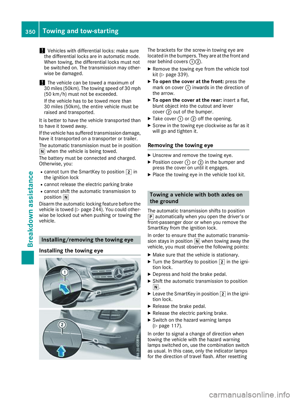
Installing the towing eye The brackets for the screw-in towing eye are
located in the bumpers. They are at the front and
rear behind covers CD .X
Remove the towing eye from the vehicle tool
kit ( Y
page 339). X
To open the cover at the front: press the
mark on cover C inwards in the direction of
the arrow. X
To open the cover at the rear: insert a flat,
blunt object into the cutout and lever
cover D out of the bumper. X
Take cover C or D off the opening.X
Screw in the towing eye clockwise as far as it
will go and tighten it.
Removing the towing eye X
Unscrew and remove the towing eye. X
Position cover C or D in the bumper and
press the cover on until it engages. X
Place the towing eye in the vehicle tool kit.
Towing a vehicle with both axles on
the ground The automatic transmission shifts to position
] automatically when you open the driver's or
front-passenger door or when you remove the
SmartKey from the ignition lock.
In order to ensure that the automatic transmis-
sion stays in position \\ when towing away the
vehicle, you must observe the following points: X
Make sure that the vehicle is stationary. X
Turn the SmartKey to position H in the igni-
tion lock. X
Depress and hold the brake pedal. X
Shift the automatic transmission to position
\\ . X
Leave the SmartKey in position H in the igni-
tion lock. X
Release the brake pedal. X
Release the electric parking brake. X
Switch on the hazard warning lamps
( Y
page 117).
In order to signal a change of direction when
towing the vehicle with the hazard warning
lamps switched on, use the combination switch
as usual. In this case, only the indicator lamps
for the direction of travel flash. After resetting350
Towing and tow-starting
Breakdown assistance
Page 353 of 398
the combination switch, the hazard warning
lamp starts flashing again.
Transporting the vehicle
4MATIC vehicles/vehicles with auto-
matic transmission
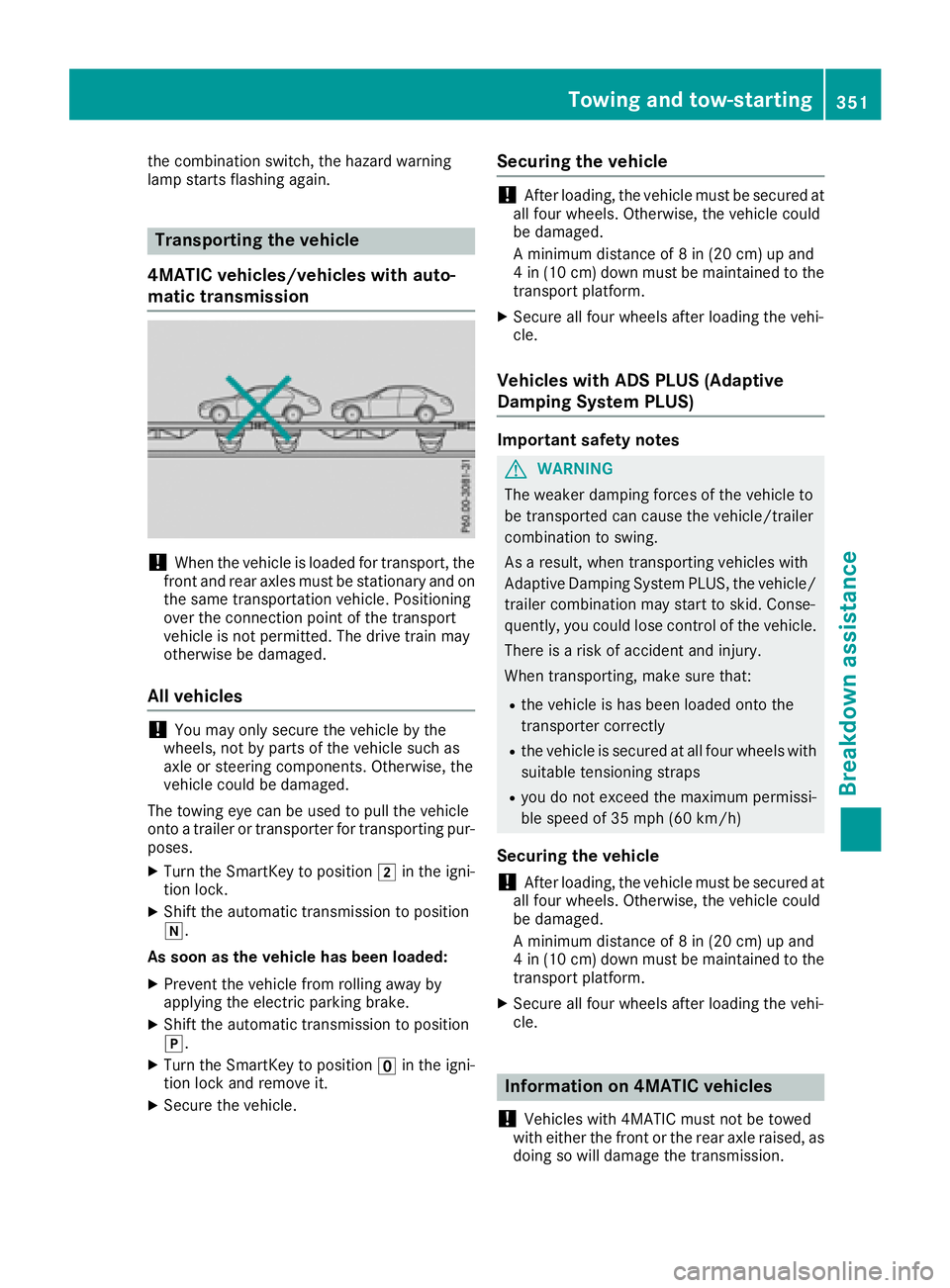
! When the vehicle is loaded for transport, the
front and rear axles must be stationary and on
the same transportation vehicle. Positioning
over the connection point of the transport
vehicle is not permitted. The drive train may
otherwise be damaged.
All vehicles
! You may only secure the vehicle by the
wheels, not by parts of the vehicle such as
axle or steering components. Otherwise, the
vehicle could be damaged.
The towing eye can be used to pull the vehicle
onto a trailer or transporter for transporting pur-
poses. X
Turn the SmartKey to position H in the igni-
tion lock. X
Shift the automatic transmission to position
\\ .
As soon as the vehicle has been loaded: X
Prevent the vehicle from rolling away by
applying the electric parking brake. X
Shift the automatic transmission to position
] . X
Turn the SmartKey to position
Page 368 of 398
able cargo and luggage load capacity is
650 lbs (1400 - 750 (5 x 150) = 650 lbs). X
Step 5: Determine the combined weight of
luggage and cargo being loaded on the vehi- cle. That weight may not safely exceed the
available cargo and luggage load capacity cal-
culated in step 4.
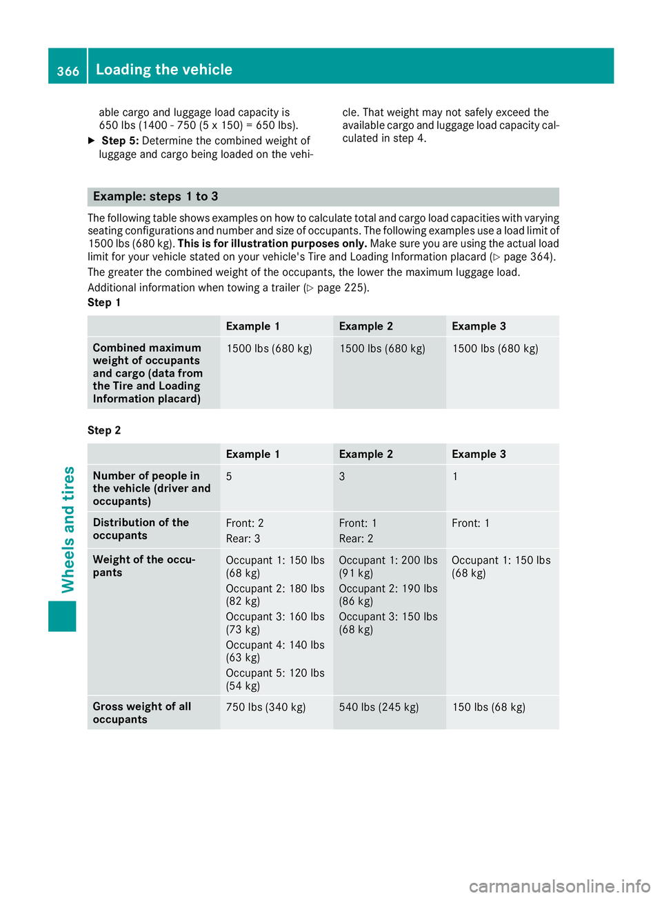
Example: steps 1 to 3 The following table shows examples on how to calculate total and cargo load capacities with varying
seating configurations and number and size of occupants. The following examples use a load limit of
1500 lbs (680 kg). This is for illustration purposes only. Make sure you are using the actual load
limit for your vehicle stated on your vehicle's Tire and Loading Information placard ( Y
page 364).
The greater the combined weight of the occupants, the lower the maximum luggage load.
Additional information when towing a trailer ( Y
page 225).
Step 1
Example 1 Example 2 Example 3
Combined maximum
weight of occupants
and cargo (data from
the Tire and Loading
Information placard) 1500 lbs (680 kg) 1500 lbs (680 kg) 1500 lbs (680 kg)
Step 2
Example 1 Example 2 Example 3
Number of people in
the vehicle (driver and
occupants) 5 3 1
Distribution of the
occupants Front: 2
Rear: 3 Front: 1
Rear: 2 Front: 1
Weight of the occu-
pants Occupant 1: 150 lbs
(68 kg)
Occupant 2: 180 lbs
(82 kg)
Occupant 3: 160 lbs
(73 kg)
Occupant 4: 140 lbs
(63 kg)
Occupant 5: 120 lbs
(54 kg) Occupant 1: 200 lbs
(91 kg)
Occupant 2: 190 lbs
(86 kg)
Occupant 3: 150 lbs
(68 kg) Occupant 1: 150 lbs
(68 kg)
Gross weight of all
occupants 750 lbs (340 kg) 540 lbs (245 kg) 150 lbs (68 kg)366
Loading the vehicle
Wheels and tires
Page 383 of 398
Removing/stowing the emergency
spare wheel
Vehicles with a "Minispare" emergency
spare wheel under the cargo compart-
ment floor Always observe the instructions and safety
notes in the "Mounting a wheel" section
( Y
page 375).
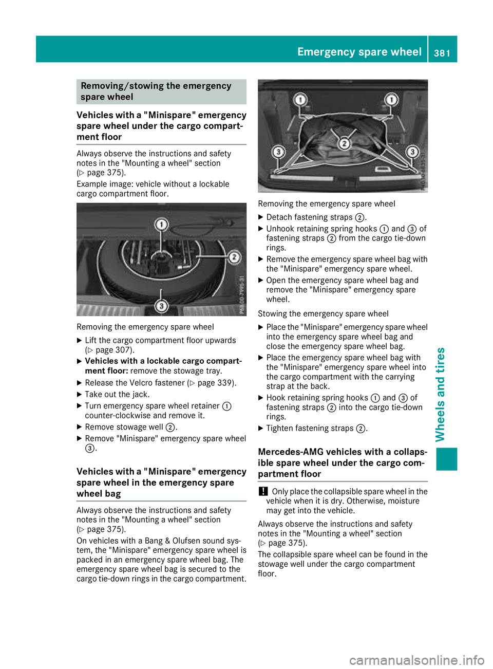
Example image: vehicle without a lockable
cargo compartment floor.
Removing the emergency spare wheel X
Lift the cargo compartment floor upwards
( Y
page 307). X
Vehicles with a lockable cargo compart-
ment floor: remove the stowage tray.X
Release the Velcro fastener ( Y
page 339).X
Take out the jack. X
Turn emergency spare wheel retainer C
counter-clockwise and remove it. X
Remove stowage well D .X
Remove "Minispare" emergency spare wheel