clock MERCEDES-BENZ GLS 2019 Owners Manual
[x] Cancel search | Manufacturer: MERCEDES-BENZ, Model Year: 2019, Model line: GLS, Model: MERCEDES-BENZ GLS 2019Pages: 398, PDF Size: 7.3 MB
Page 86 of 398
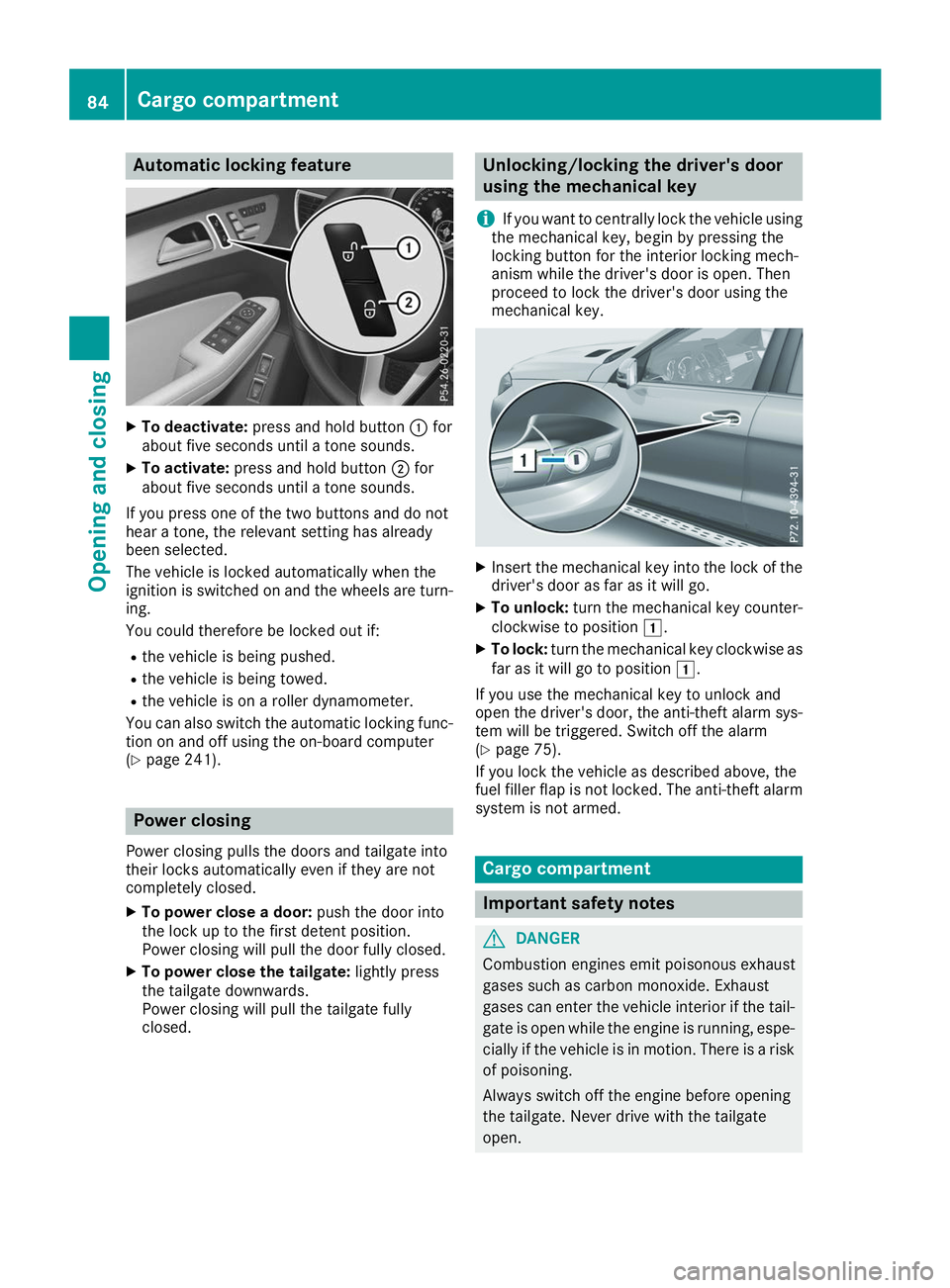
Automatic locking feature
X
To deactivate: press and hold button 0043for
about five seconds until a tone sounds.
X To activate: press and hold button 0044for
about five seconds until a tone sounds.
If you press one of the two buttons and do not
hear a tone, the relevant setting has already
been selected.
The vehicle is locked automatically when the
ignition is switched on and the wheels are turn-
ing.
You could therefore be locked out if:
R the vehicle is being pushed.
R the vehicle is being towed.
R the vehicle is on a roller dynamometer.
You can also switch the automatic locking func-
tion on and off using the on-board computer
(Y page 241). Power closing
Power closing pulls the doors and tailgate into
their locks automatically even if they are not
completely closed.
X To power close a door: push the door into
the lock up to the first detent position.
Power closing will pull the door fully closed.
X To power close the tailgate: lightly press
the tailgate downwards.
Power closing will pull the tailgate fully
closed. Unlocking/locking the driver's door
using the mechanical key
i If you want to centrally lock the vehicle using
the mechanical key, begin by pressing the
locking button for the interior locking mech-
anism while the driver's door is open. Then
proceed to lock the driver's door using the
mechanical key. X
Insert the mechanical key into the lock of the
driver's door as far as it will go.
X To unlock: turn the mechanical key counter-
clockwise to position 0047.
X To lock: turn the mechanical key clockwise as
far as it will go to position 0047.
If you use the mechanical key to unlock and
open the driver's door, the anti-theft alarm sys- tem will be triggered. Switch off the alarm
(Y page 75).
If you lock the vehicle as described above, the
fuel filler flap is not locked. The anti-theft alarm
system is not armed. Cargo compartment
Important safety notes
G
DANGER
Combustion engines emit poisonous exhaust
gases such as carbon monoxide. Exhaust
gases can enter the vehicle interior if the tail- gate is open while the engine is running, espe-cially if the vehicle is in motion. There is a risk of poisoning.
Always switch off the engine before opening
the tailgate. Never drive with the tailgate
open. 84
Cargo compartmentOpening and closing
Page 123 of 398
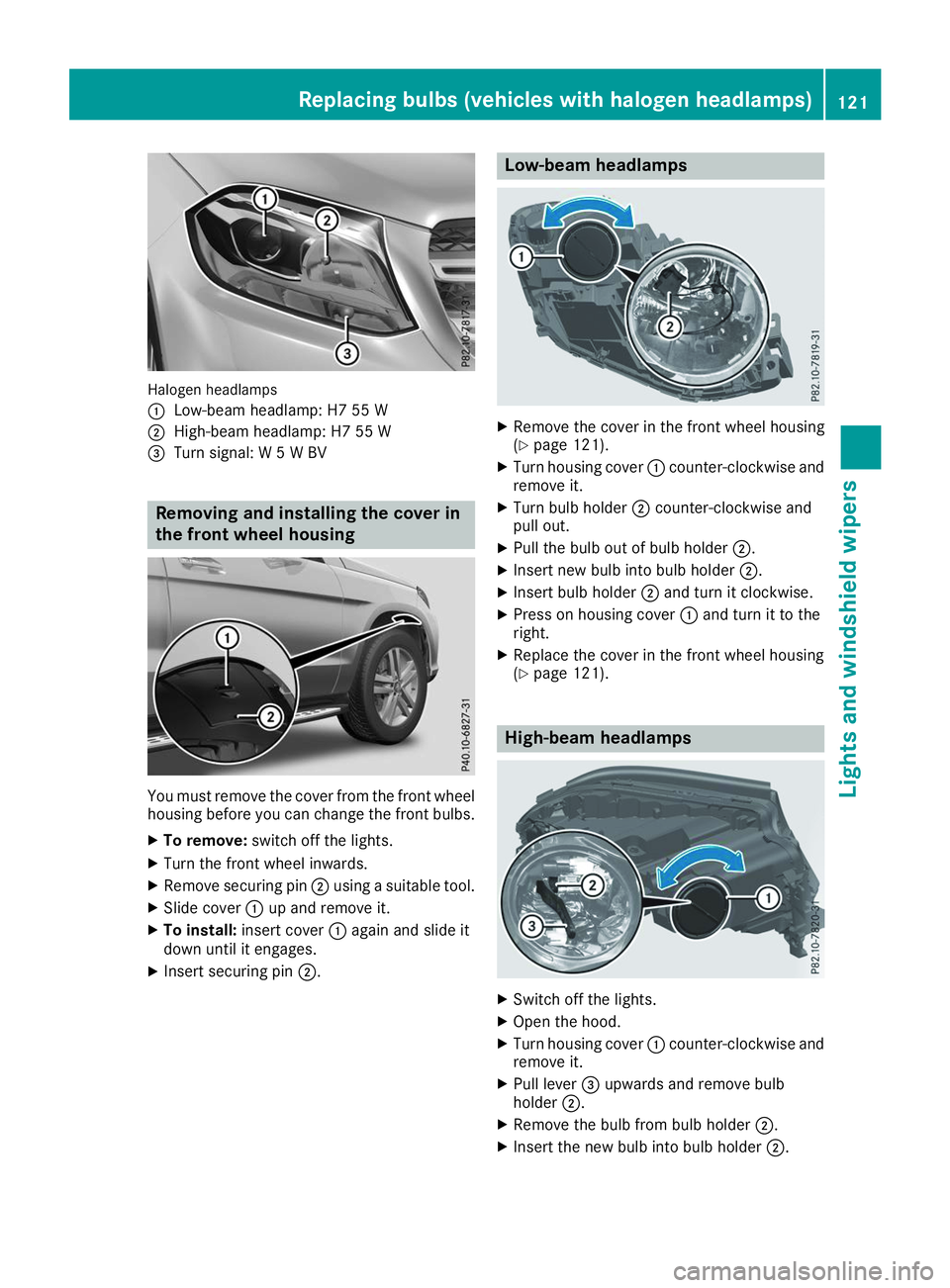
Halogen headlamps
0043
Low-beam headlamp: H7 55 W
0044 High-beam headlamp: H7 55 W
0087 Turn signal: W 5 W BV Removing and installing the cover in
the front wheel housing You must remove the cover from the front wheel
housing before you can change the front bulbs.
X To remove: switch off the lights.
X Turn the front wheel inwards.
X Remove securing pin 0044using a suitable tool.
X Slide cover 0043up and remove it.
X To install: insert cover 0043again and slide it
down until it engages.
X Insert securing pin 0044. Low-beam headlamps
X
Remove the cover in the front wheel housing
(Y page 121).
X Turn housing cover 0043counter-clockwise and
remove it.
X Turn bulb holder 0044counter-clockwise and
pull out.
X Pull the bulb out of bulb holder 0044.
X Insert new bulb into bulb holder 0044.
X Insert bulb holder 0044and turn it clockwise.
X Press on housing cover 0043and turn it to the
right.
X Replace the cover in the front wheel housing
(Y page 121). High-beam headlamps
X
Switch off the lights.
X Open the hood.
X Turn housing cover 0043counter-clockwise and
remove it.
X Pull lever 0087upwards and remove bulb
holder 0044.
X Remove the bulb from bulb holder 0044.
X Insert the new bulb into bulb holder 0044. Replacing bulbs (vehicles with halogen headlamps)
121Lights and windshield wipers Z
Page 124 of 398
X
Simultaneously press on bulb holder 0044and
pull lever 0087downwards.
X Press on housing cover 0043and turn it clock-
wise. Turn signals
X
Switch off the lights.
X Open the hood.
X Turn housing cover 0043counter-clockwise and
remove it.
X Turn bulb holder 0044counter-clockwise and
pull out.
X Pull the bulb out of bulb holder 0044.
X Insert new bulb into bulb holder 0044.
X Insert bulb holder 0044and turn it clockwise.
X Press on housing cover 0043and turn it to the
right. Windshield wipers
Switching the windshield wipers
on/off
! Do not operate the windshield wipers when
the windshield is dry, as this could damage
the wiper blades. Moreover, dust that has col-
lected on the windshield can scratch the glass
if wiping takes place when the windshield is
dry.
If it is necessary to switch on the windshield
wipers in dry weather conditions, always use
washer fluid when operating the windshield
wipers.
! If the windshield wipers leave smears on the
windshield after the vehicle has been washed
in an automatic car wash, wax or other resi-
dues may be the reason for this. Clean the windshield using washer fluid after washing
the vehicle in an automatic car wash.
! Intermittent wiping with rain sensor: due to
optical influences and the windshield becom- ing dirty in dry weather conditions, the wind-
shield wipers may be activated inadvertently. This could then damage the windshield wiper
blades or scratch the windshield.
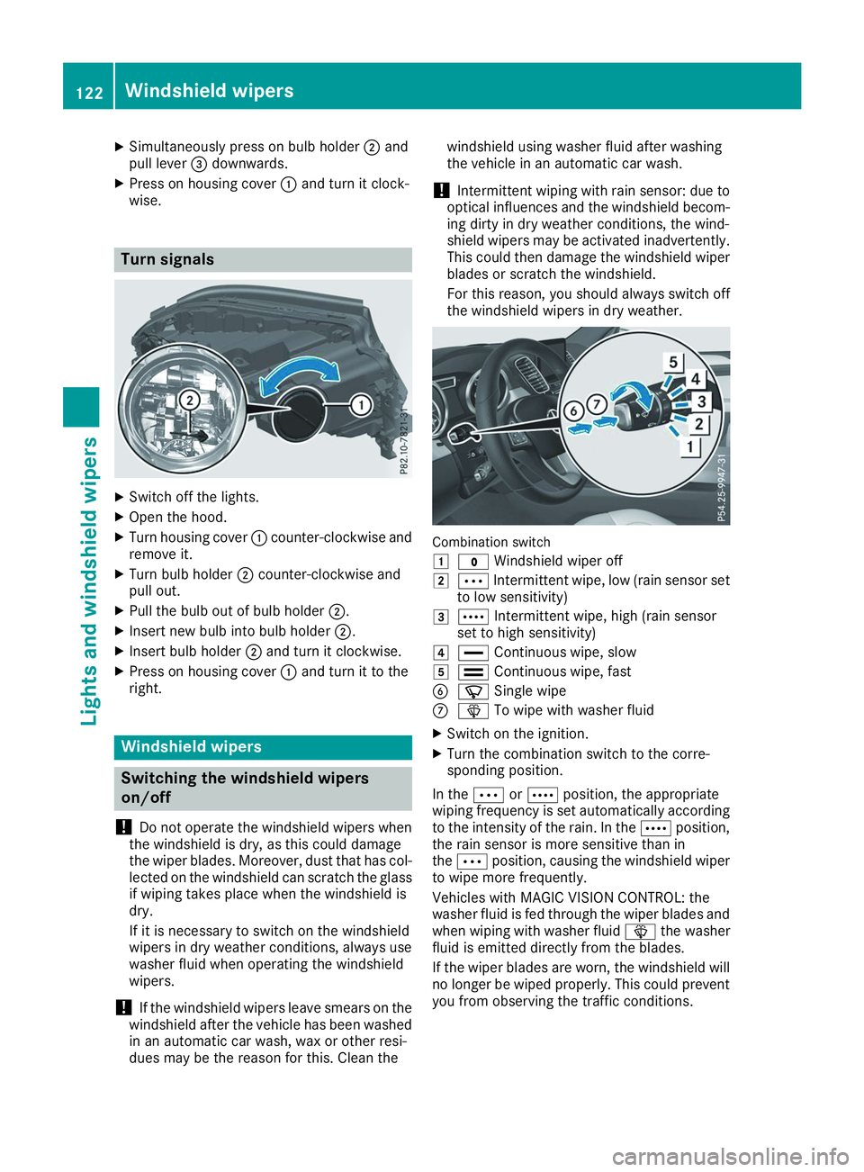
For this reason, you should always switch off the windshield wipers in dry weather. Combination switch
0047
003F Windshield wiper off
0048 0062 Intermittent wipe, low (rain sensor set
to low sensitivity)
0049 0063 Intermittent wipe, high (rain sensor
set to high sensitivity)
004A 00AA Continuous wipe, slow
004B 00A9 Continuous wipe, fast
0084 00D3 Single wipe
006B 00D4 To wipe with washer fluid
X Switch on the ignition.
X Turn the combination switch to the corre-
sponding position.
In the 0062or0063 position, the appropriate
wiping frequency is set automatically according
to the intensity of the rain. In the 0063position,
the rain sensor is more sensitive than in
the 0062 position, causing the windshield wiper
to wipe more frequently.
Vehicles with MAGIC VISION CONTROL: the
washer fluid is fed through the wiper blades and when wiping with washer fluid 00D4the washer
fluid is emitted directly from the blades.
If the wiper blades are worn, the windshield will no longer be wiped properly. This could prevent
you from observing the traffic conditions. 122
Windshield wipersLights and windshield wipers
Page 134 of 398
Problems with the "Cooling with air dehumidification" function
Problem
Possible causes/consequences and
0050
0050Solutions The indicator lamp in the
005A or0056 button
flashes three times or
remains off. The "Cool-
ing with air dehumidifi-
cation" function cannot
be switched on. Cooling with air dehumidification has been deactivated due to a mal-
function.
X Visit a qualified specialist workshop. Setting climate control to automatic
General notes In automatic mode, the set temperature is main-
tained automatically at a constant level. The
system automatically regulates the temperature of the dispensed air, the airflow and the air dis- tribution.
The "Cooling with air dehumidification" function
is activated automatically in automatic mode.
In the rear compartment, you can also switch
climate control for the rear seats to automatic
mode using the 0058button.
Automatic control X
Turn the SmartKey to position 0048in the igni-
tion lock (Y page 140).
X Set the desired temperature.
X To activate: press the0058button.
The indicator lamp in the 0058button lights
up. Automatic air distribution and airflow are
activated.
X To switch to manual mode: press the008F
button.
3-zone automatic climate control: when auto-
matic mode is activated, you can select a cli-
mate mode (Y page 132). Adjusting the climate mode settings
You can select the following climate mode set-
tings in automatic mode:
FOCUS high airflow, slightly cooler setting
MEDIUM medium airflow, standard setting
DIFFUSE low airflow, slightly warmer and draft- free setting X
Turn the SmartKey to position 0048in the igni-
tion lock (Y page 140).
X Press the 0058button.
X Press the 00F0button repeatedly until the
desired climate mode appears in the display. Setting the temperature
Dual-zone automatic climate control Different temperatures can be set for the driv-
er's and front-passenger sides.
X Turn the SmartKey to position 0048in the igni-
tion lock (Y page 140).
X To increase or decrease: turn control0043or
0084 counter-clockwise or clockwise
(Y page 125).
Only change the temperature setting in small
increments. Start at 72 ‡ (22 †).
3-zone automatic climate control You can select different temperature settings
for the driver's and front-passenger sides as well
as for the rear compartment.
X Turn the SmartKey to position 0048in the igni-
tion lock (Y page 140).
X To increase or decrease temperature in
the front compartment:
turn control0043or
0084 counter-clockwise or clockwise
(Y page 127).
Only change the temperature setting in small
increments. Start at 72 ‡ (22 †).
X To increase or reduce the temperature in
the rear compartment using the front con-
trol panel: press the00D6button.
The indicator lamp in the 00D6button goes
out. 132
Operating the climate control systemsClimate control
Page 135 of 398
The temperature setting for the driver's side
is adopted for the rear compartment and the
front-passenger side.
X Turn thumbwheel 0043to the left or right
(Y page 127).
Only change the temperature setting in small
increments. Start at 72 ‡ (22 †).
X To increase or decrease the rear compart-
ment temperature using the rear control
panel: turn control 0075counter-clockwise or
clockwise on the rear control panel
(Y page 127).
Only change the temperature setting in small
increments. Start at 72 ‡ (22 †). Setting the air distribution
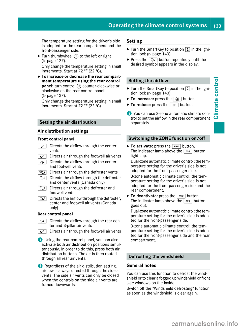
Air distribution settings Front control panel
009C
Directs the airflow through the center
vents
009B Directs air through the footwell air vents
009F Directs the airflow through the center
and footwell vents
0061 Directs air through the defroster vents
0087 Directs the airflow through the defroster
and center vents (Canada only)
0086 Directs air through the defroster and
footwell vents
008F Directs the airflow through the defroster,
center and footwell air vents (Canada
only)
Rear control panel
0099 Directs the airflow through the rear cen-
ter and B-pillar air vents
009B Directs air through the footwell air vents
i Using the rear control panel, you can also
activate both air distribution positions simul-
taneously. In order to do this, press both air
distribution buttons. The air is then routed
through all rear air vents.
i Regardless of the air distribution setting,
airflow is always directed through the side air vents. The side air vents can only be closed
when the controls on the side air vents are
turned downwards. Setting X
Turn the SmartKey to position 0048in the igni-
tion lock (Y page 140).
X Press the 008Fbutton repeatedly until the
desired symbol appears in the display. Setting the airflow
X Turn the SmartKey to position 0048in the igni-
tion lock (Y page 140).
X To increase: press the0097button.
X To reduce: press the0095button.
i You can use 3-zone automatic climate con-
trol to set the airflow in the rear compartment
separately. Switching the ZONE function on/off
X To activate: press the00D6button.
The indicator lamp above the 00D6button
lights up.
Dual-zone automatic climate control: the tem-
perature setting for the driver's side is not
adopted for the front-passenger side.
3-zone automatic climate control: the tem-
perature setting for the driver's side is not
adopted for the front-passenger side and the rear compartment.
X To deactivate: press the00D6button.
The indicator lamp above the 00D6button
goes out.
Dual-zone automatic climate control: the tem-
perature setting for the driver's side is adop-
ted for the front-passenger side.
3-zone automatic climate control: the tem-
perature setting for the driver's side is adop-
ted for the front-passenger side and the rear
compartment. Defrosting the windshield
General notes You can use this function to defrost the wind-
shield or to clear a fogged up windshield or front
side windows on the inside.
Switch off the "Windshield defrosting" function
as soon as the windshield is clear again. Operating the climate control systems
133Climate control
Page 159 of 398
X
Switch off the engine.
X Remove the SmartKey from the ignition lock.
or, on vehicles with KEYLESS ‑GO:
X Open the driver's door.
The vehicle electronics will now be in key
position 0092. This is the same as the SmartKey
having been removed.
The driver’s door can be closed again.
X Press the fuel filler flap in the direction of
arrow 0043.
The fuel filler flap swings up.
X Turn the fuel filler cap counter-clockwise and
remove it.
X Insert the fuel filler cap into the holder
bracket on the inside of filler flap 0044.
X Completely insert the filler neck of the fuel
pump nozzle into the tank, hook in place and refuel.
X Only fill the tank until the pump nozzle
switches off. Do not add any more fuel after the pump stops
filling for the first time. Otherwise, fuel may leak
out.
Closing the fuel filler flap X
Replace the cap on the filler neck and turn
clockwise until it engages audibly.
X Close the fuel filler flap.
Close the fuel filler flap before locking the vehi-
cle.
If you are driving with the fuel filler cap open, the
00B6 reserve fuel warning lamp flashes. A mes-
sage appears in the multifunction display
(Y page 260).
In addition, the 00B9Check Engine warning
lamp may light up (Y page 282). Problems with fuel and the fuel tank
Problem
Possible causes/consequences and
0050 0050Solutions Fuel is leaking from the
vehicle.
G
WARNING
The fuel line or the fuel tank is faulty.
Risk of explosion or fire. X Apply the electric parking brake.
X Switch off the engine.
X Remove the SmartKey from the ignition lock.
or, on vehicles with KEYLESS ‑GO:
X Open the driver's door.
The vehicle electronics will now be in key position 0092. This is the
same as the SmartKey having been removed.
X Do not restart the engine under any circumstances.
X Consult a qualified specialist workshop. The fuel filler flap cannot
be opened. The fuel filler flap is not unlocked.
X Unlock the vehicle (Y page 77). The SmartKey battery is discharged or nearly discharged.
X Unlock the vehicle using the mechanical key (Y page 79). The fuel filler flap is unlocked, but the opening mechanism is jammed.
X Consult a qualified specialist workshop. Refueling
157Driving and parking Z
Page 184 of 398
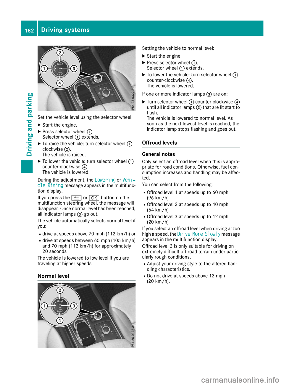
Set the vehicle level using the selector wheel.
X Start the engine.
X Press selector wheel 0043.
Selector wheel 0043extends.
X To raise the vehicle: turn selector wheel 0043
clockwise 0044.
The vehicle is raised.
X To lower the vehicle: turn selector wheel 0043
counter-clockwise 0085.
The vehicle is lowered.
During the adjustment, the Lowering
Lowering orVehi‐
Vehi‐
cle
cle Rising
Rising message appears in the multifunc-
tion display.
If you press the 0038or0076 button on the
multifunction steering wheel, the message will
disappear. Once normal level has been reached, all indicator lamps 0087go out.
The vehicle automatically selects normal level if
you:
R drive at speeds above 70 mph (112 km/h) or
R drive at speeds between 65 mph (105 km/h)
and 70 mph (112 km/h) for approximately
20 seconds
The vehicle is lowered to low level if you are
traveling at higher speeds.
Normal level Setting the vehicle to normal level:
X Start the engine.
X Press selector wheel 0043.
Selector wheel 0043extends.
X To lower the vehicle: turn selector wheel 0043
counter-clockwise 0085.
The vehicle is lowered.
If one or more indicator lamps 0087are on:
X Turn selector wheel 0043counter-clockwise 0085
until all indicator lamps 0087that are lit start to
flash.
The vehicle is lowered to normal level. As
soon as the next lowest level is reached, the
indicator lamp stops flashing and goes out.
Offroad levels General notes
Only select an offroad level when this is appro-
priate for road conditions. Otherwise, fuel con-
sumption increases and handling may be affec- ted.
You can select from the following:
R Offroad level 1 at speeds up to 60 mph
(96 km/h)
R Offroad level 2 at speeds up to 40 mph
(64 km/h)
R Offroad level 3 at speeds up to 12 mph
(20 km/h)
If you select an offroad level when driving at too high a speed, the Drive DriveMore
MoreSlowly
Slowly message
appears in the multifunction display.
Offroad level 3 is only suitable for driving on
extremely difficult off-road terrain under partic- ularly rough conditions.
R Adjust your driving style to the altered han-
dling characteristics.
R Do not drive at speeds above 12 mph
(20 km/h). 182
Driving systemsDriving and parking
Page 185 of 398
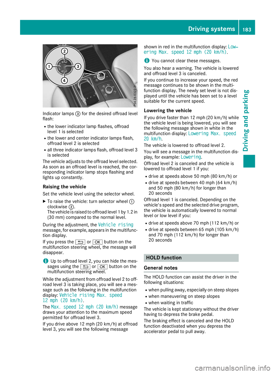
Indicator lamps
0087for the desired offroad level
flash:
R the lower indicator lamp flashes, offroad
level 1 is selected
R the lower and center indicator lamps flash,
offroad level 2 is selected
R all three indicator lamps flash, offroad level 3
is selected
The vehicle adjusts to the offroad level selected.
As soon as an offroad level is reached, the cor-
responding indicator lamp stops flashing and
lights up constantly.
Raising the vehicle
Set the vehicle level using the selector wheel.
X To raise the vehicle: turn selector wheel 0043
clockwise 0044.
The vehicle is raised to offroad level 1 by 1.2 in
(30 mm) compared to the normal level.
During the adjustment, the Vehicle rising
Vehicle rising
message, for example, appears in the multifunc-
tion display.
If you press the 0038or0076 button on the
multifunction steering wheel, the message will
disappear.
i Up to offroad level 2, you can hide the mes-
sages using the 0038or0076 button on the
multifunction steering wheel.
While the adjustment from offroad level 2 to off-
road level 3 is taking place, you will see a mes-
sage such as the following in the multifunction
display: Vehicle rising Max. speed
Vehicle rising Max. speed
12 mph (20 km/h) 12 mph (20 km/h).
The Max. Max. speed
speed 12 mph
12 mph (20 km/h)
(20 km/h) message
draws your attention to the maximum speed
permitted for offroad level 3.
If you drive above 12 mph (20 km/h) at offroad
level 3, you will see the following message shown in red in the multifunction display:
Low‐ Low‐
ering Max. speed 12 mph (20 km/h)
ering Max. speed 12 mph (20 km/h).
i You cannot clear these messages.
You also hear a warning. The vehicle is lowered and offroad level 3 is canceled.
If you continue to increase your speed, the red
message continues to be shown in the multi-
function display. The newly set level is not dis-
played until the vehicle has been set to a level
suitable for the current speed.
Lowering the vehicle If you drive faster than 12 mph (20 km/h) while
the vehicle level is being lowered, you will see
the following message shown in white in the
multifunction display: Lowering Max. speed Lowering Max. speed
20 km/h
20 km/h.
The vehicle is lowered to offroad level 2.
You will see a message in the multifunction dis- play, for example: Lowering Lowering.
Offroad level 2 is canceled and the vehicle is
lowered to offroad level 1 if you:
R drive at speeds above 50 mph (80 km/h) or
R drive at speeds between 40 mph (64 km/h)
and 50 mph (80 km/h) for longer than
20 seconds
Offroad level 1 is canceled. Depending on the
vehicle's speed and the selected drive program,
the vehicle is automatically lowered to normal
level or low level if you:
R drive at speeds above 70 mph (112 km/h) or
R drive at speeds between 65 mph (105 km/h)
and 70 mph (112 km/h) for longer than
20 seconds HOLD function
General notes The HOLD function can assist the driver in the
following situations:
R when pulling away, especially on steep slopes
R when maneuvering on steep slopes
R when waiting in traffic
The vehicle is kept stationary without the driver
having to depress the brake pedal.
The braking effect is canceled and the HOLD
function deactivated when you depress the
accelerator pedal to pull away. Driving systems
183Driving and parking Z
Page 232 of 398
Important safety notes
G
WARNING
If you operate information systems and com-
munication equipment integrated in the vehi- cle when driving, you may be distracted from
the traffic situation. You could also lose con-
trol of the vehicle. There is a risk of an acci-
dent.
Only operate this equipment when the traffic
situation permits. If you are not sure that this
is possible, park the vehicle paying attention
to traffic conditions and operate the equip-
ment when the vehicle is stationary.
You must observe the legal requirements for the country in which you are currently driving whenoperating the on-board computer. G
WARNING
If the instrument cluster has failed or mal-
functioned, you may not recognize function
restrictions in systems relevant to safety. The operating safety of your vehicle may be
impaired. There is a risk of an accident.
Drive on carefully. Have the vehicle checked
at a qualified specialist workshop immedi-
ately.
If the operating safety of your vehicle is
impaired, pull over as soon as it is safe to do so.
Contact a qualified specialist workshop.
The on-board computer only shows messages or warnings from certain systems in the multifunc-tion display. You should therefore make sure
your vehicle is operating safely at all times.
For an overview, see the instrument panel illus-
tration (Y page 37). Displays and operation
Instrument cluster lighting
The lighting in the instrument cluster, in the dis-
plays and the controls in the vehicle interior can be adjusted using the brightness control knob.
The brightness control knob is located on the
bottom left of the instrument cluster
(Y page 37). X
Turn the brightness control knob clockwise or
counter-clockwise.
If you turn the light switch to 0058,0060or
0058, the brightness is dependent upon the
brightness of the ambient light.
i The light sensor in the instrument cluster
automatically controls the brightness of the
multifunction display.
In daylight, the displays in the instrument
cluster are not illuminated. Speedometer with segments
The segments in the speedometer indicate
which speed range is available.
R Cruise control activated (Y page 171):
The segments light up from the stored speed to the maximum speed.
R Active Distance Assist DISTRONIC activated
(Y page 172):
One or two segments in the set speed range
light up.
R Active Distance Assist DISTRONIC detects a
vehicle in front moving more slowly than the
stored speed:
The segments between the speed of the vehi- cle in front and the stored speed light up. Tachometer
! Do not drive in the overrevving range, as this
could damage the engine.
The red band in the tachometer indicates the
engine's overrevving range.
The fuel supply is interrupted to protect the
engine when the red band is reached. Outside temperature display
You should pay special attention to road condi-
tions when temperatures are around freezing
point.
Bear in mind that the outside temperature dis-
play indicates the temperature measured and
does not record the road temperature.
The outside temperature display is in the multi-
function display (Y page 232).230
Displays and operationOn-board computer and displays
Page 325 of 398
When checking the oil level:
R
park the vehicle on a level surface.
R the engine should be switched off for approx-
imately five minutes if the engine is at normal
operating temperature.
R if the engine is not at normal operating tem-
perature, e.g. if the engine was only started
briefly, wait about 30 minutes before carrying
out the measurement.
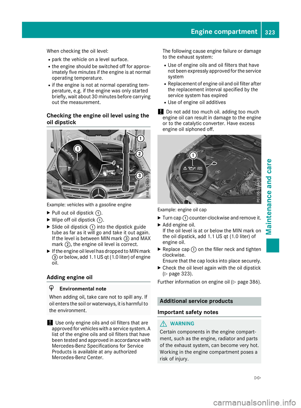
Checking the engine oil level using the
oil dipstick Example: vehicles with a gasoline engine
X Pull out oil dipstick 0043.
X Wipe off oil dipstick 0043.
X Slide oil dipstick 0043into the dipstick guide
tube as far as it will go and take it out again.
If the level is between MIN mark 0087and MAX
mark 0044, the engine oil level is correct.
X If the engine oil level has dropped to MIN mark
0087 or below, add 1.1 US qt (1.0 liter) of engine
oil.
Adding engine oil H
Environmental note
When adding oil, take care not to spill any. If
oil enters the soil or waterways, it is harmful to the environment.
! Use only engine oils and oil filters that are
approved for vehicles with a service system. A list of the engine oils and oil filters that have
been tested and approved in accordance with
Mercedes-Benz Specifications for Service
Products is available at any authorized
Mercedes-Benz Center. The following cause engine failure or damage
to the exhaust system:
R Use of engine oils and oil filters that have
not been expressly approved for the service
system
R Replacement of engine oil and oil filter after
the replacement interval specified by the
service system has expired
R Use of engine oil additives
! Do not add too much oil. adding too much
engine oil can result in damage to the engine or to the catalytic converter. Have excess
engine oil siphoned off. Example: engine oil cap
X Turn cap 0043counter-clockwise and remove it.
X Add engine oil.
If the oil level is at or below the MIN mark on
the oil dipstick, add 1.1 US qt (1.0 liter) of
engine oil.
X Replace cap 0043on the filler neck and tighten
clockwise.
Ensure that the cap locks into place securely.
X Check the oil level again with the oil dipstick
(Y page 323).
Further information on engine oil (Y page 386). Additional service products
Important safety notes G
WARNING
Certain components in the engine compart-
ment, such as the engine, radiator and parts
of the exhaust system, can become very hot.
Working in the engine compartment poses a
risk of injury. Engine compartment
323Maintenance and care
Z