oil pressure MERCEDES-BENZ GLS 2019 Owners Manual
[x] Cancel search | Manufacturer: MERCEDES-BENZ, Model Year: 2019, Model line: GLS, Model: MERCEDES-BENZ GLS 2019Pages: 398, PDF Size: 7.3 MB
Page 23 of 398
Tailgate
Display message ............................ 271
Emergency unlocking ....................... 88
Important safety notes .................... 84
Limiting the opening angle ............... 88
Opening dimensions ...................... 389
Opening/closing (automatically
from inside) ...................................... 87
Opening/closing (automatically
from outside) ................................... 86
Opening/closing (from outside) ....... 85
Power closing .................................. 84
Tank
see Fuel tank
Tank content
Fuel gaug e....................................... 37
Technical data
Capacities ...................................... 384
Drawbar load (maximum) ............... 392
Information .................................... 382
Tires/wheels ................................. 377
Trailer load s................................... 392
Vehicle data ................................... 389
Telephone
Accepting a call (multifunction
steering wheel) .............................. 237
Authorizing a mobile phone (con-
necting) ......................................... 291
Authorizing a mobile phone via the device manager (connecting) ......... 292
Connecting a mobile phone
(device manager )........................... 292
Connecting a mobile phone (gen-
eral information) ............................ 291
Display message ............................ 272
Menu (on-board computer) ............ 237
Number from the phone book ........ 237
Redialing ........................................ 237
Rejecting/ending a call ................. 237
see also Digital Operator's Man-
ua l.................................................. 287
Temperature
Coolant (display in the instrument
cluster) .......................................... 231
Coolant (on-board computer,
Mercedes-AMG vehicles) ............... 242
Engine oil (on-board computer,
Mercedes-AMG vehicles) ............... 242 Outside temperature ...................... 230
Setting (climate control
)................ 132
Transmission oil (on-board com-
puter, Mercedes-AMG vehicles) ..... 242
Through-loading feature ................... 298
Timing (RACETIMER) ......................... 243
Tire pressure
Calling up (on-board computer) ..... 359
Checking manually ........................ 358
Display message ............................ 268
Maximum ....................................... 358
Not reached (TIREFIT) .................... 339
Note s............................................. 357
Reached (TIREFIT) .......................... 339
Recommended ............................... 355
Tire pressure loss warning system
General notes ................................ 358
Important safety notes .................. 359
Restarting ...................................... 359
Tire pressure monitor
Checking the tire pressure elec-
tronically ........................................ 361
Function/note s............................. 359
General notes ................................ 359
Important safety notes .................. 360
Radio type approval for the tire
pressure monitor ........................... 362
Restarting ...................................... 362
Warning lamp ................................. 286
Warning message .......................... 361
Tire pressure table ............................ 356
TIREFIT kit
Important safety notes .................. 337
Storage location ............................ 335
Tire pressure not reached .............. 339
Tire pressure reached .................... 339
Using ............................................. 338
Tires
Aspect ratio (definition) ................. 372
Average weight of the vehicle
occupants (definition) .................... 370
Bar (definition) ............................... 370
Changing a whee l.......................... 372
Characteristics .............................. 370
Checking ........................................ 352
Curb weight (definition) ................. 371
Definition of terms ......................... 370
Direction of rotation ...................... 373 Index
21
Page 170 of 398
R
Take care when turning on an uphill or down-
hill slope or when driving across a slope. The
vehicle could otherwise tip over.
R Always keep the doors, the tailgate, the side
windows and the sliding sunroof closed while the vehicle is in motion.
R Do not shift the automatic transmission to
position 005C.
R Observe the notes on off-road fording
(Y page 165).
i Information about retrofitting special all-ter-
rain tires is available from any qualified spe-
cialist workshop.
i Do not use the HOLD function when driving
off-road, on steep uphill or downhill gradients
or on slippery or loose surfaces. The HOLD
function cannot hold the vehicle on such sur- faces.
Checklist before driving off-road !
If the engine oil warning lamp lights up while
the vehicle is in motion, stop the vehicle in a
safe place as soon as possible. Check the
engine oil level. The engine oil warning lamp
warning must not be ignored. Continuing the
journey while the symbol is displayed could
lead to engine damage.
X Engine oil level: check the engine oil level
and add engine oil if necessary.
When you drive on steep gradients, the engine
oil level must be sufficiently high to ensure
that oil is supplied correctly in the vehicle.
X Tire-changing tool kit: check that the jack is
working and make sure you have the lug
wrench, a robust tow cable and a folding
spade in the vehicle.
X Wheels and tires: check the tread depth and
pressure of the tires.
X Check for damage and remove any foreign
objects, e.g. small stones, from the wheels/
tires.
X Replace any missing valve caps.
X Replace dented or damaged wheels.
X Rims: dented or bent rims can result in a loss
of tire pressure and damage the tire bead.
Before driving off-road, check the wheels and
replace them if necessary. Checklist after driving off-road !
If you detect damage to the vehicle after
driving off-road, have the vehicle checked
immediately at a qualified specialist work-
shop.
Driving over rough terrain places greater
demands on your vehicle than driving on normal
roads. After driving off-road, check the vehicle.
This allows you to detect damage promptly and reduce the risk of an accident to yourself and
other road users.
X If the Offroad orOffroad Plus drive program
is selected: select the Individual,Sport,
Comfort orSlippery drive program
(Y page 147).
X Deactivate the LOW RANGE off-road gear
(Y page 218).
X Deactivate DSR (Y page 215).
X Lower the vehicle level again to a level suita-
ble to the road conditions, e.g. to the normal
level.
X Clean the headlamps and rear lights and
check for damage.
X Clean the front and rear license plates.
X Clean the wheels and tires with a water jet
and remove any foreign objects.
X Clean the wheels, wheel housings and the
vehicle underside with a water jet; check for
any foreign objects and damage.
X Check whether twigs or other parts of plants
have become trapped. These increase the risk of fire and can damage fuel pipes, brake
hoses or the rubber bellows of the axle joints
and propeller shafts.
X After the trip, examine without fail the entire
undercarriage, wheels, tires, brakes, body-
work structure, steering, chassis and exhaust
system for damage.
X After driving for extended periods across
sand, mud, gravel, water or in similarly dirty
conditions, have the brake discs, wheels,
brake pads/linings and axle joints checked
and cleaned.
X If you detect strong vibrations after off-road
travel, check for foreign objects in the wheels
and drive train and remove them if necessary.
Foreign objects can disturb the balance and
cause vibrations. 168
Driving tipsDriving and parking
Page 333 of 398
X
Make sure that the vehicle is stationary and
the SmartKey is in position 0048in the ignition
lock.
X Open the camera cover for cleaning via the
multimedia system (see Digital Operator's
Manual).
X To clean the camera: use clean water and a
soft cloth to clean the camera lens 0043.
360° camera: if you drive at speeds above
20 mph (30 km/h) or with the SmartKey in posi- tion 0092or0047 in the ignition lock, the cover of
the 360° camera closes.
Cleaning the exhaust pipe G
WARNING
The exhaust tail pipe and tail pipe trim can
become very hot. If you come into contact
with these parts of the vehicle, you could burn
yourself. There is a risk of burns.
Always be particularly careful and supervise
children closely around the exhaust pipe and
the exhaust pipe trims. Allow these compo-
nents to cool down before touching them.
! Vehicles with black exhaust pipes: black
chromed screens should not be polished with a chrome polish. They will otherwise lose their
black shine. For optimal care, the screens
should be rubbed with a lightly oiled cloth
after every car wash. Commercially available
engine and care oils are suitable for this.
For heavier soiling, you can apply a fine paint- work polish with a microfiber cloth. Remove
the excess polish residue after polishing.
Impurities combined with the effects of road grit
and corrosive environmental factors may cause flash rust to form on the surface. You can
restore the original shine of the exhaust pipe by
cleaning it regularly, especially in winter and
after washing.
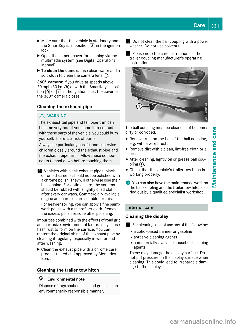
X Clean the exhaust pipe with a chrome care
product tested and approved by Mercedes-
Benz.
Cleaning the trailer tow hitch H
Environmental note
Dispose of rags soaked in oil and grease in an environmentally responsible manner. !
Do not clean the ball coupling with a power
washer. Do not use solvents.
! Please note the care instructions in the
trailer coupling manufacturer's operating
instructions. The ball coupling must be cleaned if it becomes
dirty or corroded.
X Remove rust on the ball of the ball coupling,
e.g. with a wire brush.
X Remove dirt with a clean, lint-free cloth or a
brush.
X After cleaning, lightly oil or grease ball cou-
pling 0043.
X Check that the vehicle's trailer tow hitch is
working properly.
i You can also have the maintenance work on
the ball coupling and the trailer tow hitch car-
ried out by a qualified specialist workshop. Interior care
Cleaning the display !
For cleaning, do not use any of the following:
R alcohol-based thinner or gasoline
R abrasive cleaning agents
R commercially-available household cleaning
agents
These may damage the display surface. Do
not put pressure on the display surface when
cleaning. This could lead to irreparable dam-
age to the display. Care
331Maintenance and care Z
Page 340 of 398
Using the TIREFIT kit
X
Do not remove any foreign objects which have
penetrated the tire, e.g. screws or nails.
X Remove the tire sealant bottle, the accompa-
nying TIREFIT sticker and the tire inflation
compressor from the stowage well under-
neath the cargo compartment floor
(Y page 335).
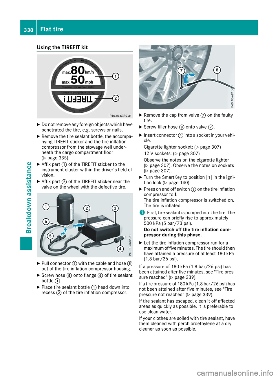
X Affix part 0043of the TIREFIT sticker to the
instrument cluster within the driver's field of
vision.
X Affix part 0044of the TIREFIT sticker near the
valve on the wheel with the defective tire. X
Pull connector 0085with the cable and hose 0083
out of the tire inflation compressor housing.
X Screw hose 0083onto flange 0084of tire sealant
bottle 0043.
X Place tire sealant bottle 0043head down into
recess 0044of the tire inflation compressor. X
Remove the cap from valve 006Bon the faulty
tire.
X Screw filler hose 006Conto valve 006B.
X Insert connector 0085into a socket in your vehi-
cle.
Cigarette lighter socket: (Y page 307)
12 V sockets: (Y page 307)
Observe the notes on the cigarette lighter
(Y page 307). Observe the notes on sockets
(Y page 307).
X Turn the SmartKey to position 0047in the igni-
tion lock (Y page 140).
X Press on and off switch 0087on the tire inflation
compressor to I.
The tire inflation compressor is switched on.
The tire is inflated.
i First, tire sealant is pumped into the tire. The
pressure can briefly rise to approximately
500 kPa (5 bar/73 psi).
Do not switch off the tire inflation com-
pressor during this phase.
X Let the tire inflation compressor run for a
maximum of five minutes. The tire should then
have attained a pressure of at least 180 kPa
(1.8 bar/26 psi).
If a pressure of 180 kPa (1.8 bar/26 psi) has
been attained after five minutes, see "Tire pres-
sure reached" (Y page 339).
If a tire pressure of 180 kPa (1.8 bar/26 psi) has not been attained after five minutes, see "Tire
pressure not reached" (Y page 339).
If tire sealant has escaped, clean it off affected
areas as quickly as possible. It is preferable to
use clean water.
If your clothes are soiled with tire sealant, have
them cleaned with perchloroethylene at a dry
cleaner as soon as possible. 338
Flat tireBreakdown assistance
Page 373 of 398
Recommended tire pressures
The recommended tire pressure applies to the
tires mounted at the factory.
The Tire and Loading Information placard con-
tains the recommended tire pressures for cold
tires on a fully loaded vehicle and for the maxi-
mum permissible vehicle speed.
The tire pressure table contains the recommen- ded pressures for cold tires for various operat-
ing conditions, i.e. differing load and speed con- ditions.
Increased vehicle weight due to optional
equipment The combined weight of all standard and
optional equipment available for the vehicle,
regardless of whether it is actually installed on
the vehicle or not.
Rim This is the part of the wheel on which the tire is
mounted.
GAWR (Gross Axle Weight Rating)
The GAWR is the maximum gross axle weight
rating. The actual load on an axle must never
exceed the gross axle weight rating. The gross
axle weight rating can be found on the vehicle
identification plate on the B-pillar on the driver's side.
Speed rating
The speed rating is part of the tire identification. It specifies the speed range for which the tire isapproved.
GTW (Gross Trailer Weight)
The GTW is the weight of a trailer including the
weight of the load, luggage, accessories etc. on the trailer.
GVW (Gross Vehicle Weight) The gross vehicle weight includes the weight of
the vehicle including fuel, tools, the spare wheel, accessories installed, occupants, luggage and
the drawbar noseweight, if applicable. The gross vehicle weight must not exceed the gross vehi-
cle weight rating GVWR as specified on the vehi-
cle identification plate on the B-pillar on the
driver's side. GVWR (Gross Vehicle Weight Rating)
The GVWR is the maximum permissible gross
weight of a fully loaded vehicle (the weight of the
vehicle including all accessories, occupants,
fuel, luggage and the drawbar noseweight, if
applicable). The gross vehicle weight rating is
specified on the vehicle identification plate on
the B-pillar on the driver's side.
Maximum loaded vehicle weight
The maximum weight is the sum of:
R the curb weight of the vehicle
R the weight of the accessories
R the load limit
R the weight of the factory installed optional
equipment
Kilopascal (kPa) Metric unit for tire pressure. 6.9 kPa corre-
sponds to 1 psi. Another unit for tire pressure is
bar. 100 kilopascals (kPa) are the equivalent of
1 bar.
Load index
In addition to the load-bearing index, the load
index may also be imprinted on the sidewall of
the tire. This specifies the load-bearing capacity more precisely.
Curb weight
The weight of a vehicle with standard equipment
including the maximum capacity of fuel, oil and
coolant. It also includes the air-conditioning sys- tem and optional equipment if these are instal-
led in the vehicle, but does not include passen-
gers or luggage.
Maximum load rating
The maximum tire load is the maximum permis- sible weight in kilograms or lbs for which a tire is
approved.
Maximum permissible tire pressure
Maximum permissible tire pressure for one tire.
Maximum load on one tire
Maximum load on one tire. This is calculated by
dividing the maximum axle load of one axle by
two. All about wheels and tires
371Wheels and tires Z
Page 375 of 398
ponents may also be damaged. There is a risk
of an accident.
Rotate front and rear wheels only if the wheels
and tires are of the same dimensions.
! On vehicles equipped with a tire pressure
monitor, electronic components are located
in the wheel.
Tire-mounting tools should not be used near
the valve. This could damage the electronic
components.
Only have tires changed at a qualified spe-
cialist workshop.
Always observe the instructions and safety
notes in the "Mounting a wheel" section
(Y page 373).
The wear patterns on the front and rear tires
differ, depending on the operating conditions.
Rotate the wheels before a clear wear pattern
has formed on the tires. Front tires typically
wear more on the shoulders and the rear tires in
the center.
On vehicles that have the same size front and
rear wheels, you can rotate the wheels accord-
ing to the intervals in the tire manufacturer's
warranty book in your vehicle documents. If no
warranty book is available, the tires should be
rotated every 3,000 to 6,000 miles (5,000 to
10,000 km). Depending on tire wear, this may
be required earlier. Do not change the direction
of wheel rotation.
Clean the contact surfaces of the wheel and the brake disc thoroughly every time a wheel is rota-
ted. Check the tire pressure and, if necessary,
restart the tire pressure loss warning system or
the tire pressure monitor (Y page 359).Direction of rotation
Tires with a specified direction of rotation have
additional benefits, e.g. if there is a risk of hydro-
planing. These advantages can only be gained if the tires are installed corresponding to the
direction of rotation.
An arrow on the sidewall of the tire indicates its
correct direction of rotation. Storing wheels
Store wheels that are not being used in a cool,
dry and preferably dark place. Protect the tires
from oil, grease, gasoline and diesel. Mounting a wheel
Preparing the vehicle X
Vehicle with emergency spare wheel:
when mounting the emergency spare wheel in
the event of a flat tire, follow the additional
notes on vehicle preparation under "Flat tire" (Y page 335).
X Stop the vehicle on solid, non-slippery and
level ground.
X Apply the electric parking brake manually.
X Bring the front wheels into the straight-ahead
position.
X Vehicles with automatic transmission:
shift the transmission to position
005D.
X Vehicles with the AIRMATIC package:
make sure that the normal vehicle level is
selected (Y page 187).
X Vehicles with the Off-Road Engineering
package:
make sure that the normal level is
selected (Y page 180).
X Switch off the engine.
X Vehicles without KEYLESS-GO: remove the
SmartKey from the ignition lock.
X Vehicles with KEYLESS-GO: open the driv-
er's door.
The vehicle electronics are now in position
0092. This means no SmartKey is in the ignition lock.
X Vehicles with KEYLESS-GO: remove the
Start/Stop button from the ignition lock
(Y page 140).
X If included in the vehicle equipment, remove
the tire-change tool kit from the vehicle.
X Safeguard the vehicle against rolling away.
i Apart from certain country-specific varia-
tions, vehicles are not equipped with a tire-
change tool kit. For more information on
which tools are required to perform a wheel
change on your vehicle, consult a qualified
specialist workshop. Changing a wheel
373Wheels and tires Z