tow bar MERCEDES-BENZ GLS SUV 2016 Owners Manual
[x] Cancel search | Manufacturer: MERCEDES-BENZ, Model Year: 2016, Model line: GLS SUV, Model: MERCEDES-BENZ GLS SUV 2016Pages: 397, PDF Size: 14.21 MB
Page 18 of 397
Storing the current speed .............. 183
Variabl
e......................................... 183
Limiting the speed
see Speed limiter
Loading guidelines ............................ 312
Locking
see Central locking
Locking (doors)
Automatic ........................................ 88
Emergency locking ........................... 89
From inside (central locking but-
ton) .................................................. 88
Locking centrally
see Central locking
Locking verification signal (on-
board computer) ............................... 253
LOW RANGE
Display message ............................ 277
Off-road gear ................................. 230
LOW RANGE off-road gear ................ 230
Luggage compartment cover
Notes/function .............................. 317
Luggage compartment enlarge-
ment
Important safety notes .................. 315
Luggage compartment floor
Important safety notes .................. 318
opening/closing ............................ 319
stowage well, under ....................... 318
Lumbar support
Adjusting (on the seat) .................. 112
Luxury head restraint ....................... 105M
M+S tyres ........................................... 363
Main-beam headlamps
Adaptive Highbeam Assist PLUS .... 124
Display message ............................ 270
Replacing bulb s............................. 127
Switching on/of f........................... 122
Maintenance
see ASSYST PLUS
Matt finish (cleaning instructions) .. 339
MB Contact
Display message ............................ 264 Media Interface
USB port in the armrest of the
centre console ............................... 313
see Digital Owner's Manual
Memory card (audio) ......................... 247
Memory function ............................... 118
Mercedes-Benz emergency call
system
Switch in the overhead control
panel .............................................. 324
Mercedes-Benz Intelligent Drive
360°camera .................................. 212
Active Blind Spot Assist ................. 222
Active Lane Keeping Assist ............ 224
ATTENTION ASSIST ........................ 216
Blind Spot Assist ............................ 219
Distance Pilot DISTRONIC ............. 184
Distance Pilot DISTRONIC with
Steering Pilot ................................. 191
General notes ................................ 180
Lane Keeping Assist ...................... 221
Parking Assist PARKTRONIC .......... 201
Parking Pilo t.................................. 204
PRE-SAFE ®
PLUS (anticipatory
occupant protection PLUS) .............. 56
Reversing camera .......................... 207
Traffic Sign Assist .......................... 217
Mercedes-Benz Service Centre
see Qualified specialist workshop
Message memory (on-board com-
puter) .................................................. 258
Mirror
Vanity mirror (sun visor) ................ 322
Mirror turn signal
Cleaning ......................................... 341
Mirrors
see Exterior mirrors
see Rear-view mirror
see Vanity mirror (in sun visor)
Mobile phone
Connecting (Bluetooth ®
inter-
face) .............................................. 306
Connecting another mobile
phone ............................................ 307
Connecting the telephone module
with Bluetooth ®
(SAP profile) ......... 309
Frequencies ................................... 379 Index
15
Page 204 of 397
Parking Assist PARKTRONIC
Important safety notes Parking Assist PARKTRONIC is an electronic
parking aid with ultrasound. It monitors the area
around your vehicle using six sensors in the
front bumper and six sensors in the rear
bumper. Parking Assist PARKTRONIC visually
and audibly indicates the distance between your
vehicle and an object.
Parking Assist PARKTRONIC is only an aid. It is
not a substitute for your attention to the imme-
diate surroundings. The responsibility for safe
manoeuvring and parking remains with you.
Make sure that there are no persons, animals or objects in range while manoeuvring and parking.
! When parking, pay particular attention to
objects above or below the sensors, such as
flower pots or trailer drawbars. PARKTRONIC does not detect such objects when they are in
the immediate vicinity of the vehicle. You
could damage the vehicle or the objects.
The sensors may not detect snow and objects which absorb ultrasonic sources.
Ultrasonic sources, such as an automatic car
wash, a lorry's compressed-air brakes or a
pneumatic drill, could cause PARKTRONIC to
malfunction.
PARKTRONIC may not function correctly on
uneven terrain.
! Fold in the ball coupling if the trailer tow
hitch is not required. PARKTRONIC measures the minimum detection range to an obstacle
from the bumper, not the ball coupling.
Parking Assist PARKTRONIC is deactivated for
the rear area when you establish an electrical
connection between your vehicle and a trailer.
Parking Assist PARKTRONIC is activated auto-
matically when you:
R switch on the ignition
R shift the transmission to position D,Ror N
R release the electric parking brake
Parking Assist PARKTRONIC is deactivated at
speeds above 18 km/h. It is reactivated at lower
speeds. Range of the sensors General notes
Parking Assist PARKTRONIC does not take into
account obstacles located:
R below the detection range, e.g. persons, ani-
mals or objects
R above the detection range, e.g. overhanging
loads, tail sections or loading ramps of goods
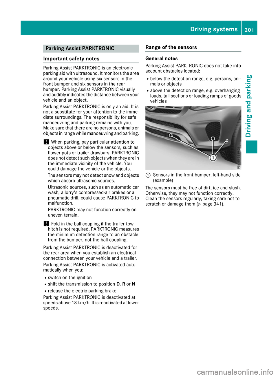
vehicles :
Sensors in the front bumper, left-hand side
(example)
The sensors must be free of dirt, ice and slush.
Otherwise, they may not function correctly.
Clean the sensors regularly, taking care not to
scratch or damage them (Y page 341). Driving systems
201Driving and parking Z
Page 212 of 397
!
Objects not at ground level may appear to
be further away than they actually are, e.g.:
R the bumper of a parked vehicle
R the drawbar of a trailer
R the ball coupling of a trailer tow hitch
R the rear section of an HGV
R a slanted post
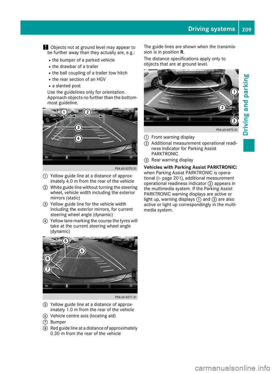
Use the guidelines only for orientation.
Approach objects no further than the bottom- most guideline. :
Yellow guide line at a distance of approx-
imately 4.0 m from the rear of the vehicle
; White guide line without turning the steering
wheel, vehicle width including the exterior
mirrors (static)
= Yellow guide line for the vehicle width
including the exterior mirrors, for current
steering wheel angle (dynamic)
? Yellow lane marking the course the tyres will
take at the current steering wheel angle
(dynamic) A
Yellow guide line at a distance of approx-
imately 1.0 m from the rear of the vehicle
B Vehicle centre axis (locating aid)
C Bumper
D Red guide line at a distance of approximately
0.30 m from the rear of the vehicle The guide lines are shown when the transmis-
sion is in position R.
The distance specifications apply only to
objects that are at ground level. :
Front warning display
; Additional measurement operational readi-
ness indicator for Parking Assist
PARKTRONIC
= Rear warning display
Vehicles with Parking Assist PARKTRONIC:
when Parking Assist PARKTRONIC is opera-
tional (Y page 201), additional measurement
operational readiness indicator ;appears in
the multimedia system. If the Parking Assist
PARKTRONIC warning displays are active or
light up, warning displays :and =are also
active or light up correspondingly in the multi-
media system. Driving systems
209Driving and parking Z
Page 214 of 397
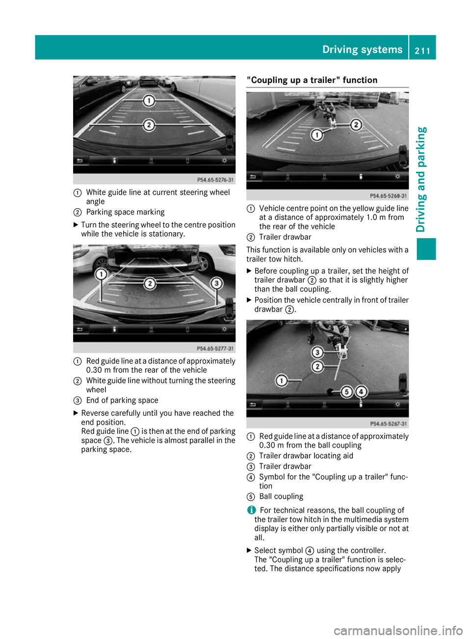
:
White guide line at current steering wheel
angle
; Parking space marking
X Turn the steering wheel to the centre position
while the vehicle is stationary. :
Red guide line at a distance of approximately
0.30 m from the rear of the vehicle
; White guide line without turning the steering
wheel
= End of parking space
X Reverse carefully until you have reached the
end position.
Red guide line :is then at the end of parking
space =. The vehicle is almost parallel in the
parking space. "Coupling up a trailer" function :
Vehicle centre point on the yellow guide line
at a distance of approximately 1.0 m from
the rear of the vehicle
; Trailer drawbar
This function is available only on vehicles with a
trailer tow hitch.
X Before coupling up a trailer, set the height of
trailer drawbar ;so that it is slightly higher
than the ball coupling.
X Position the vehicle centrally in front of trailer
drawbar ;. :
Red guide line at a distance of approximately
0.30 m from the ball coupling
; Trailer drawbar locating aid
= Trailer drawbar
? Symbol for the "Coupling up a trailer" func-
tion
A Ball coupling
i For technical reasons, the ball coupling of
the trailer tow hitch in the multimedia system
display is either only partially visible or not at all.
X Select symbol ?using the controller.
The "Coupling up a trailer" function is selec-
ted. The distance specifications now apply Driving systems
211Driving and parking Z
Page 215 of 397
only to objects that are at the same level as
the ball coupling.
X Reverse carefully, making sure that trailer
drawbar locating aid ;points approximately
in the direction of trailer drawbar =.
X Reverse carefully until trailer drawbar =rea-
ches the red guide line.
The distance between the trailer drawbar and
the red guide line is now approximately
0.30 m.
X Couple up the trailer (Y page 234).
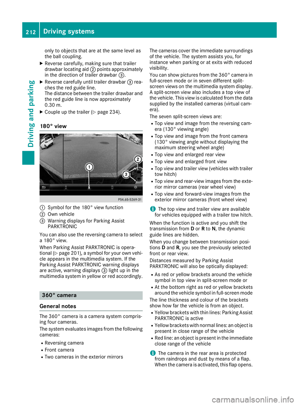
180° view :
Symbol for the 180° view function
; Own vehicle
= Warning displays for Parking Assist
PARKTRONIC
You can also use the reversing camera to select
a 180° view.
When Parking Assist PARKTRONIC is opera-
tional (Y page 201), a symbol for your own vehi-
cle appears in the multimedia system. If the
Parking Assist PARKTRONIC warning displays
are active, warning displays =light up in the
multimedia system in yellow or red accordingly. 360° camera
General notes The 360° camera is a camera system compris-
ing four cameras.
The system evaluates images from the following
cameras:
R Reversing camera
R Front camera
R Two cameras in the exterior mirrors The cameras cover the immediate surroundings
of the vehicle. The system assists you, for
instance when parking or at exits with reduced
visibility.
You can show pictures from the 360° camera in full-screen mode or in seven different split-
screen views on the multimedia system display. A split-screen view also includes a top view of
the vehicle. This view is calculated from the data
supplied by the installed cameras (virtual cam-
era).
The seven split-screen views are:
R Top view and image from the reversing cam-
era (130° viewing angle)
R Top view and image from the front camera
(130° viewing angle without displaying the
maximum steering wheel angle)
R Top view and enlarged rear view
R Top view and enlarged front view
R Top view and trailer view (vehicles with trailer
tow hitch)
R Top view and rear-view images from the exte-
rior mirror cameras (rear wheel view)
R Top view and forward-view images from the
exterior mirror cameras (front wheel view)
i The top view and trailer view are available
for vehicles equipped with a trailer tow hitch.
When the function is active and you shift the
transmission from Dor Rto N, the dynamic
guide lines are hidden.
When you change between transmission posi-
tions Dand R, you see the previously selected
front or rear view.
Distances measured by Parking Assist
PARKTRONIC will also be optically displayed:
R As red or yellow brackets around the vehicle
symbol in top view in split-screen mode or
R At the bottom right as red or yellow brackets
around the vehicle symbol in full-screen mode
The line thickness and colour of the brackets
show how far the vehicle is from an object.
R Yellow brackets with thin lines: Parking Assist
PARKTRONIC is active
R Yellow brackets with normal lines: an object is
present in close range of the vehicle
R Red line: an object is present in the immediate
close range of the vehicle
i The camera in the rear area is protected
from raindrops and dust by means of a flap.
When the camera is activated, this flap opens. 212
Driving systemsDriving and parking
Page 217 of 397
X
Make sure that the key is in position 2in the
ignition lock.
X Make sure that the Activation by R gear
Activation by R gear
function is selected in the multimedia system (see the separate operating instructions).
X To show the 360° camera image: engage
reverse gear.
The multimedia system shows the area
behind the vehicle in split-screen mode. You
see the top view of the vehicle and the image from the reversing camera.
Selecting the split-screens or 180° view Selecting split-screen view
X To switch to the line with the vehicle icons:
slide 5the controller.
X To select one of the vehicle icons: turn 3
the controller.
X To switch to 180° view 180° view:turn 3 the con-
troller to select 180° view
180° view and press7to
confirm.
i The
180°
180° view
viewoption is only available in the
following views:
R Top view with image from the reversing
camera
R Top view with image from the front camera
Displays in the multimedia system Important safety notes
The camera system may show a distorted view
of obstacles or show them incorrectly or not at
all. Obstacles in the following locations are not
shown by the system:
R Under the front and rear bumpers
R Very close to the front and rear bumpers
R In the area immediately above the recessed
tailgate handle
R Very close to the exterior mirrors
R In the transitional areas between the various
cameras in the virtual top view
! Objects not at ground level may appear to
be further away than they actually are, e.g.:
R the bumper of a parked vehicle
R the drawbar of a trailer
R the ball coupling of a trailer tow hitch R
the rear section of an HGV
R a slanted post
Use the guidelines only for orientation.
Approach objects no further than the bottom- most guideline.
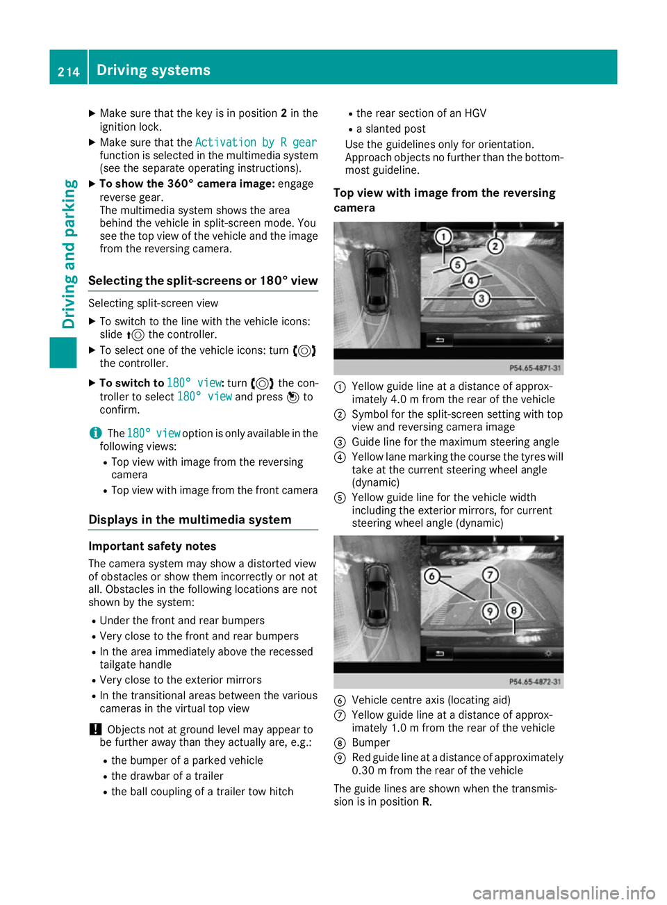
Top view with image from the reversing
camera :
Yellow guide line at a distance of approx-
imately 4.0 m from the rear of the vehicle
; Symbol for the split-screen setting with top
view and reversing camera image
= Guide line for the maximum steering angle
? Yellow lane marking the course the tyres will
take at the current steering wheel angle
(dynamic)
A Yellow guide line for the vehicle width
including the exterior mirrors, for current
steering wheel angle (dynamic) B
Vehicle centre axis (locating aid)
C Yellow guide line at a distance of approx-
imately 1.0 m from the rear of the vehicle
D Bumper
E Red guide line at a distance of approximately
0.30 m from the rear of the vehicle
The guide lines are shown when the transmis-
sion is in position R.214
Driving systemsDriving and parking
Page 220 of 397
X
Select the assistance graphic display for
ATTENTION ASSIST using the on-board com-
puter (Y page 249).
The following information is displayed:
R The length of the journey since the last break
R The attention level determined by ATTENTION
ASSIST, displayed in a bar display in five levelsfrom high to low
R If ATTENTION ASSIST is unable to calculate
the attention level and cannot output a warn-
ing, the System suspended
System suspended message
appears. The bar display then changes the
display, e.g. if you are driving at a speed below
60 km/h or above 200 km/h.
Activating ATTENTION ASSIST X
Activate ATTENTION ASSIST using the on-
board computer (Y page 250).
The system determines the attention level of
the driver depending on the setting selected:
Standard selected: the sensitivity with which
the system determines the attention level is set
to normal.
Sensitive selected: the sensitivity is set higher.
The attention level detected by ATTENTION
ASSIST is adapted accordingly and the driver is
warned earlier.
When ATTENTION ASSIST is deactivated, the
À symbol and OFF appear in the multifunc-
tion display in the assistance graphics display
when the engine is running.
When ATTENTION ASSIST has been deactivated, it is automatically reactivated after the engine
has been switched off. The sensitivity selected
corresponds to the last selection activated
(standard/sensitive).
Warning in the multifunction display If fatigue or increasing lapses in concentration
are detected, a warning appears in the multi-
function display: Attention
Attention Assist: Assist:Take
Takea
a
break!
break!
In addition to the message shown in the multi-
function display, you will then hear a warning
tone.
X If necessary, take a break.
X Confirm the message by pressing the a
button on the steering wheel.
On long journeys, take regular breaks in good
time to allow yourself to rest. If you do not take a break, you will be warned again after
15 minutes at the earliest. This will happen only
if ATTENTION ASSIST still detects typical indi-
cators of fatigue or increasing lapses in concen- tration.
Vehicles with COMAND Online: if a warning is
output in the multifunction display, a service
station search is performed in COMAND Online. You can select a service station and you will then
be navigated to this service station. This func-
tion can be activated and deactivated in
COMAND Online. Traffic Sign Assist
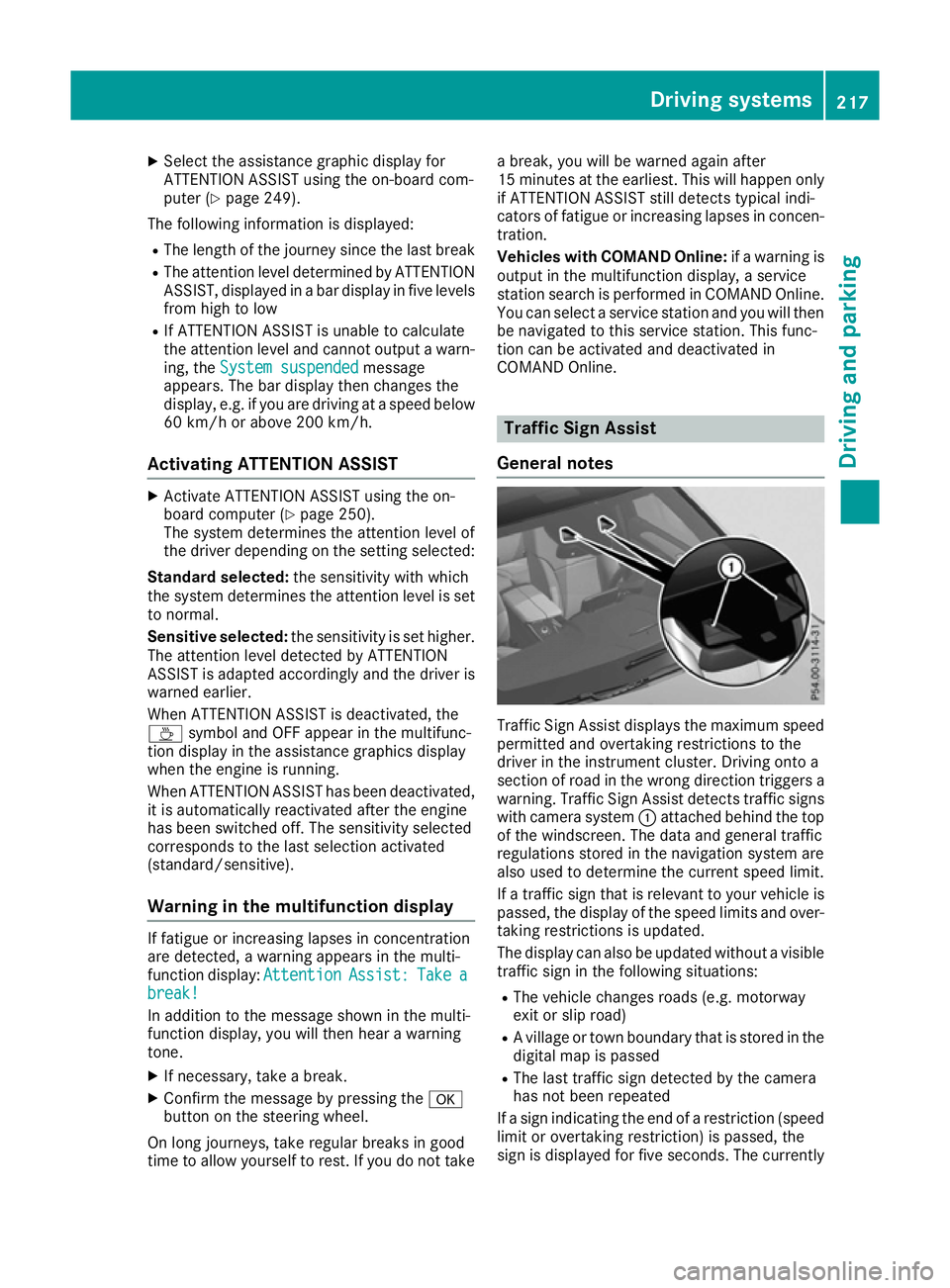
General notes Traffic Sign Assist displays the maximum speed
permitted and overtaking restrictions to the
driver in the instrument cluster. Driving onto a
section of road in the wrong direction triggers a
warning. Traffic Sign Assist detects traffic signs with camera system :attached behind the top
of the windscreen. The data and general traffic
regulations stored in the navigation system are
also used to determine the current speed limit.
If a traffic sign that is relevant to your vehicle is passed, the display of the speed limits and over-
taking restrictions is updated.
The display can also be updated without a visible traffic sign in the following situations:
R The vehicle changes roads (e.g. motorway
exit or slip road)
R A village or town boundary that is stored in the
digital map is passed
R The last traffic sign detected by the camera
has not been repeated
If a sign indicating the end of a restriction (speed
limit or overtaking restriction) is passed, the
sign is displayed for five seconds. The currently Driving systems
217Driving and parking Z
Page 223 of 397
Blind Spot Assist monitors the area up to 3.0 m
behind your vehicle and directly next to your
vehicle, as shown in the picture.
If the lanes are narrow, vehicles driving in the
lane beyond the lane next to your vehicle may be
indicated, especially if the vehicles are not driv-
ing in the middle of their lane. This may be the
case if there are vehicles at the edge of their lane nearest your vehicle.
On very wide lanes, vehicles in the lane next to
your vehicle may not be displayed if the vehicles
are too far away.
Due to the nature of the system:
R warnings may be issued in error when driving
close to crash barriers or similar solid lane
borders
R warnings may be interrupted when driving
alongside long vehicles, for example lorries,
for a prolonged time
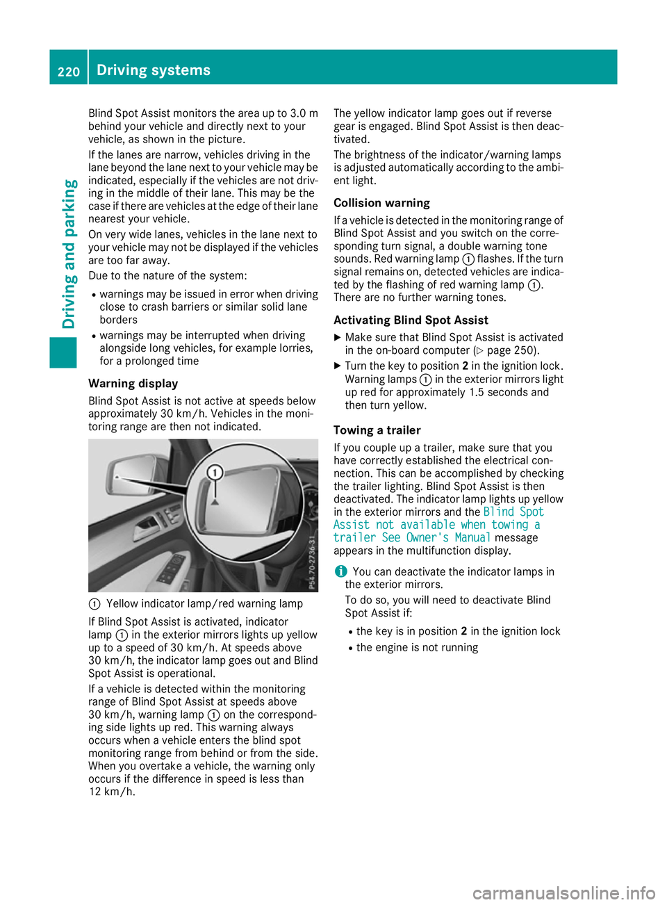
Warning display Blind Spot Assist is not active at speeds below
approximately 30 km/h. Vehicles in the moni-
toring range are then not indicated. :
Yellow indicator lamp/red warning lamp
If Blind Spot Assist is activated, indicator
lamp :in the exterior mirrors lights up yellow
up to a speed of 30 km/h. At speeds above
30 km/h, the indicator lamp goes out and Blind
Spot Assist is operational.
If a vehicle is detected within the monitoring
range of Blind Spot Assist at speeds above
30 km/h, warning lamp :on the correspond-
ing side lights up red. This warning always
occurs when a vehicle enters the blind spot
monitoring range from behind or from the side.
When you overtake a vehicle, the warning only
occurs if the difference in speed is less than
12 km/h. The yellow indicator lamp goes out if reverse
gear is engaged. Blind Spot Assist is then deac-
tivated.
The brightness of the indicator/warning lamps
is adjusted automatically according to the ambi-
ent light.
Collision warning
If a vehicle is detected in the monitoring range of
Blind Spot Assist and you switch on the corre-
sponding turn signal, a double warning tone
sounds. Red warning lamp :flashes. If the turn
signal remains on, detected vehicles are indica-
ted by the flashing of red warning lamp :.
There are no further warning tones.
Activating Blind Spot Assist
X Make sure that Blind Spot Assist is activated
in the on-board computer (Y page 250).
X Turn the key to position 2in the ignition lock.
Warning lamps :in the exterior mirrors light
up red for approximately 1.5 seconds and
then turn yellow.
Towing a trailer
If you couple up a trailer, make sure that you
have correctly established the electrical con-
nection. This can be accomplished by checking
the trailer lighting. Blind Spot Assist is then
deactivated. The indicator lamp lights up yellow
in the exterior mirrors and the Blind Spot Blind Spot
Assist not available when towing a
Assist not available when towing a
trailer See Owner's Manual
trailer See Owner's Manual message
appears in the multifunction display.
i You can deactivate the indicator lamps in
the exterior mirrors.
To do so, you will need to deactivate Blind
Spot Assist if:
R the key is in position 2in the ignition lock
R the engine is not running 220
Driving systemsDriving and parking
Page 227 of 397
G
WARNING
A course-correcting brake application cannot always prevent a collision. There is a risk of an
accident.
Always steer, brake or accelerate yourself,
especially if Active Blind Spot Assist warns
you or makes a course-correcting brake appli-
cation. Always maintain a safe distance at the sides.
If a course-correcting brake application occurs, red warning lamp :flashes in the exterior mir-
ror and a dual warning tone sounds. In addition, display underlining the danger of a side collision
appears in the multifunction display.
In very rare cases, the system may make an
inappropriate brake application. A course-cor-
recting brake application may be interrupted at any time if you steer slightly in the opposite
direction or accelerate.
The course-correcting brake application is avail-
able in the speed range between 30 km/h and
200 km/h.
Either a course-correcting brake application
appropriate to the driving situation, or none at
all, may occur in the following situations:
R there are vehicles or obstacles, e.g. crash
barriers, close to both sides of your vehicle
R a vehicle approaches too closely on the side
R you have adopted a sporty driving style with
high cornering speeds
R you brake or accelerate significantly
R a driving safety system engages, such as
ESP ®
or PRE-SAFE ®
Brake
R ESP ®
is deactivated
R the Offroad program is activated (vehicles
without the Off-Road Engineering package)
R the Offroad or Offroad Plus drive program is
activated (vehicles with the Off-Road Engi-
neering package)
R the LOW RANGE off-road gear is activated
(vehicles with the Off-Road Engineering pack-
age)
R a loss of tyre pressure or a defective tyre is
detected Activating Active Blind Spot Assist
X Make sure that Active Blind Spot Assist
(Y page 250) is activated in the on-board
computer.
X Turn the key to position 2in the ignition lock.
Warning lamps :in the exterior mirrors light
up red for approximately 1.5 seconds and
then turn yellow.
Towing a trailer
If you couple up a trailer, make sure that you
have correctly established the electrical con-
nection. This can be accomplished by checking
the trailer lighting. Active Blind Spot Assist is
then deactivated. The indicator lamps in the
exterior mirrors light up yellow and the Active
Active
Blind Spot Assist not available when Blind Spot Assist not available when
towing a trailer See Owner's Manual towing a trailer See Owner's Manual
message appears in the multifunction display.
Active Lane Keeping Assist General notes
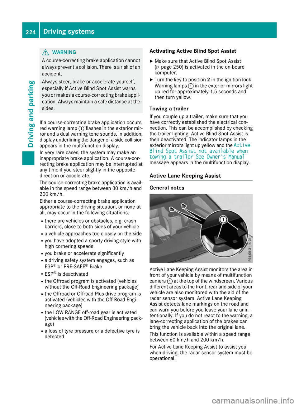
Active Lane Keeping Assist monitors the area in
front of your vehicle by means of multifunction
camera :at the top of the windscreen. Various
different areas to the front, rear and side of your vehicle are also monitored with the aid of the
radar sensor system. Active Lane Keeping
Assist detects lane markings on the road and
can warn you before you leave your lane unin-
tentionally. If you do not react to the warning, a
lane-correcting application of the brakes can
bring the vehicle back into the original lane.
This function is available within a speed range
between 60 km/h and 200 km/h.
For Active Lane Keeping Assist to assist you
when driving, the radar sensor system must be
operational. 224
Driving systemsDriving and parking
Page 236 of 397
E
Level control
F Compass with angle scale
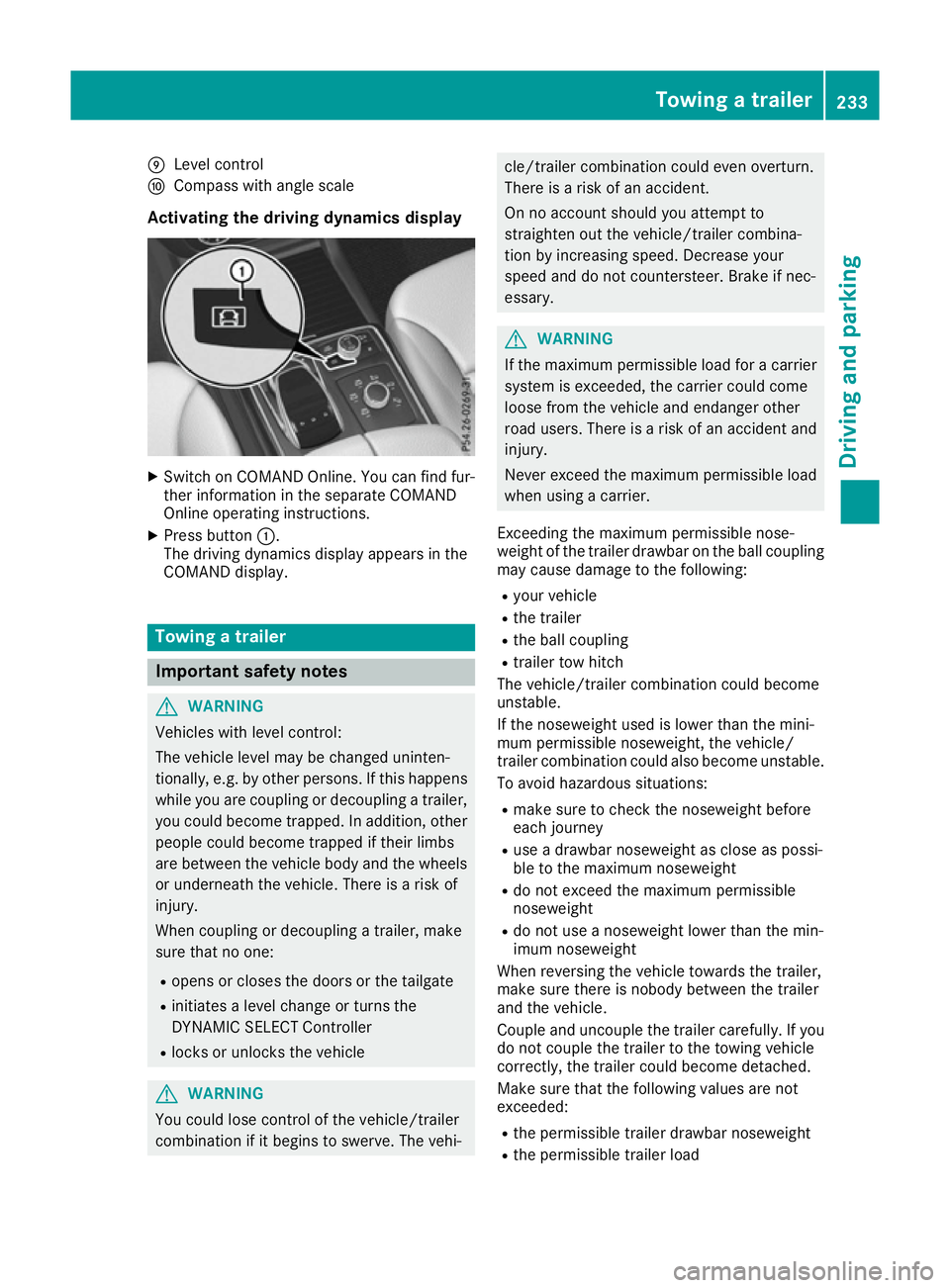
Activating the driving dynamics display X
Switch on COMAND Online. You can find fur-
ther information in the separate COMAND
Online operating instructions.
X Press button :.
The driving dynamics display appears in the
COMAND display. Towing a trailer
Important safety notes
G
WARNING
Vehicles with level control:
The vehicle level may be changed uninten-
tionally, e.g. by other persons. If this happens while you are coupling or decoupling a trailer,
you could become trapped. In addition, other
people could become trapped if their limbs
are between the vehicle body and the wheels or underneath the vehicle. There is a risk of
injury.
When coupling or decoupling a trailer, make
sure that no one:
R opens or closes the doors or the tailgate
R initiates a level change or turns the
DYNAMIC SELECT Controller
R locks or unlocks the vehicle G
WARNING
You could lose control of the vehicle/trailer
combination if it begins to swerve. The vehi- cle/trailer combination could even overturn.
There is a risk of an accident.
On no account should you attempt to
straighten out the vehicle/trailer combina-
tion by increasing speed. Decrease your
speed and do not countersteer. Brake if nec-
essary. G
WARNING
If the maximum permissible load for a carrier system is exceeded, the carrier could come
loose from the vehicle and endanger other
road users. There is a risk of an accident and injury.
Never exceed the maximum permissible load
when using a carrier.
Exceeding the maximum permissible nose-
weight of the trailer drawbar on the ball coupling
may cause damage to the following:
R your vehicle
R the trailer
R the ball coupling
R trailer tow hitch
The vehicle/trailer combination could become
unstable.
If the noseweight used is lower than the mini-
mum permissible noseweight, the vehicle/
trailer combination could also become unstable. To avoid hazardous situations:
R make sure to check the noseweight before
each journey
R use a drawbar noseweight as close as possi-
ble to the maximum noseweight
R do not exceed the maximum permissible
noseweight
R do not use a noseweight lower than the min-
imum noseweight
When reversing the vehicle towards the trailer,
make sure there is nobody between the trailer
and the vehicle.
Couple and uncouple the trailer carefully. If you do not couple the trailer to the towing vehicle
correctly, the trailer could become detached.
Make sure that the following values are not
exceeded:
R the permissible trailer drawbar noseweight
R the permissible trailer load Towing a trailer
233Driving and parking Z