exterior mirror MERCEDES-BENZ M-CLASS SUV 2011 Owners Manual
[x] Cancel search | Manufacturer: MERCEDES-BENZ, Model Year: 2011, Model line: M-CLASS SUV, Model: MERCEDES-BENZ M-CLASS SUV 2011Pages: 389, PDF Size: 9.22 MB
Page 14 of 389
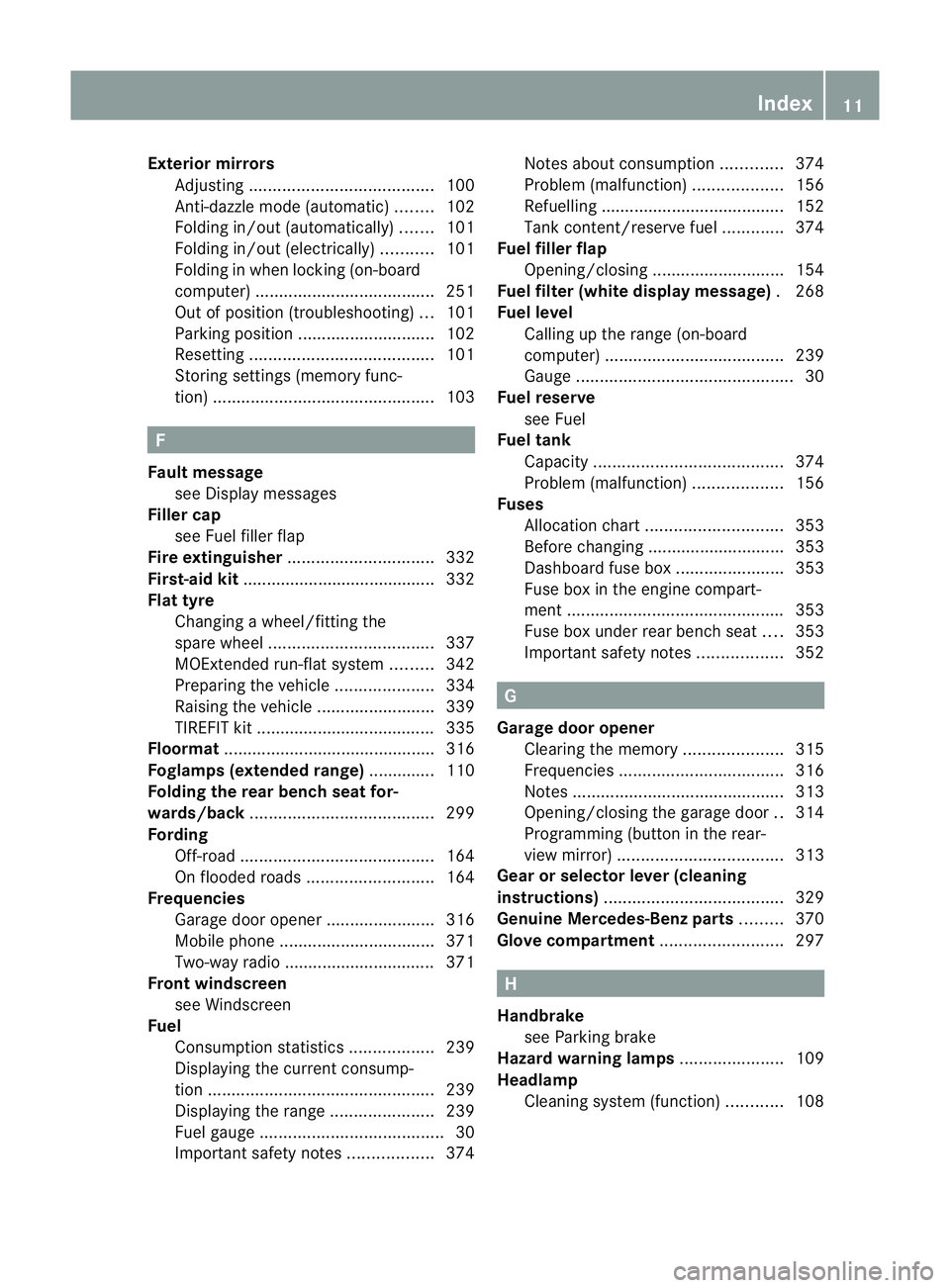
Exterior mirrors
Adjustin g....................................... 100
Anti-dazzle mod e(automatic) ........102
Fol ding in/ou t(automatically )....... 101
Fol ding in/ou t(electrically) ...........101
Fol ding in whe nlocki ng(on-board
computer) ...................................... 251
Ou tofp osition (troubleshooting) ...101
Parking positio n............................. 102
Resetting ....................................... 101
Storing settings (memory func-
tion) ............................................... 103F
Faul tmessage
see Display messages
Filler cap
see Fuel filler flap
Fire extinguisher ............................... 332
First-aid kit ......................................... 332
Flat tyre Changing awheel/fitting the
spare wheel ................................... 337
MOExtende drun-flat sy stem......... 342
Pre paring th evehicle ..................... 334
Rais ingt he vehicle ......................... 339
TIREFIT kit ...................................... 335
Floormat ............................................ .316
Foglamps (extende drang e).............. 110
Foldin gthe rear be nchs eat for-
wards/back ....................................... 299
Fording Off-road ......................................... 164
On flo oded roads ........................... 164
Frequencies
Garage door opene r....................... 316
Mobile phone ................................. 371
Tw o-way radio ................................ 371
Fron twindscreen
see Windscreen
Fuel
Consumption statistic s.................. 239
Displaying the curren tconsum p-
tion ................................................ 239
Displaying the rang e...................... 239
Fue lgauge ....................................... 30
Important safety notes ..................374Note
sabout consum ption ............. 374
Pro blem (malfunction) ................... 156
Refuellin g....................................... 152
Tank content/reserve fuel .............374
Fue lfiller flap
Opening/closing ............................ 154
Fue lfilter (white display mess age) .2 68
Fue llevel
Calling up the range (on-board
computer) ...................................... 239
Gaug e.............................................. 30
Fue lreserve
see Fuel
Fuel tank
Capacity ........................................ 374
Pro blem (malfunction) ................... 156
Fuses
Allocation chart ............................. 353
Before changing ............................. 353
Dashboard fus ebox....................... 353
Fus ebox in the engin ecompart-
men t.............................................. 353
Fus ebox under rear bench seat ....353
Important safety notes ..................352 G
Garage door opener Clearing the memory .....................315
Freq uencies ................................... 316
Note s............................................. 313
Opening/closing the garage door ..314
Programming (b utton in the rear-
view mirror) ................................... 313
Gear or se lector lever (cleaning
instructions) ...................................... 329
Genuine Mercedes-Benz parts .........370
Glove compartment ..........................297 H
Handbrake seeP arking brake
Hazard warning lamps ......................109
Headlamp Clean ings ystem (function) ............108 Index
11
Page 17 of 389
Luggage holder (EASY-PACK load-
securing kit) ...................................... .304
Luggage net ....................................... 298
Lumbar support ................................... 96M
M+S tyres ........................................... 358
Main-beam headlamps Changing bulbs .............................. 115
Display message ............................ 263
Switch ingA daptive Highbeam
Assist on/of f................................. 110
Switch ingo n/off ........................... 108
Maintenan ce
se eA SSYST PLUS service interval
display
Matt finish (cleaning instructions) ..326
Memory card (audi o)......................... 242
Memory function ............................... 103
Mercedes-Benz Service Centre seeQ ualified specialist workshop
Message memory (on-board com-
puter) ................................................. .253
Mes sages
see Display messages
Mirrors
see Exterior mirrors
see Rear-view mirror
see Vanity mirror
Mobile phone
Frequencies ................................... 371
Installati on .................................... .371
Menu (on-bo ardc omputer )............ 242
Notes/p lacing in the bracket ......... 310
Sliding adapte r............................... 312
Transmiss iono utput (maximum ).... 371
Modifying the programming (key) .....73
MOExtende drun-flat system ...........342
Motor waym ode ................................ 110
MP3 Operating ...................................... .242
se eS eparate operating instructions
Multifunction display
Function/notes ............................. 236
Permanen tdispla y......................... 246Multifuncti
onsteering wheel
Operating the on-board computer .235
Overview .......................................... 33 N
Navigation Menu (on-bo ardc omputer )............ 240
On-bo ardc omputer ....................... 240
se es eparat eoperating instructions
Nigh tView Assist Plus
Activating/deactivating .................205
Clean ing. ........................................ 328
Function/note s............................. 205
Pro blem (fault) ............................... 208
Note sonr unnin ginan ew vehicle ..138 O
Occupant safety Children in the vehicle .....................50
Important safety notes ....................40
Odometer ........................................... 239
se eT otal distance recorder
see Trip meter
Off-road driving
Checklist after driving off-road ......167
Ch ecklis tbefore driv ingo ff-roa d.... 167
General information .......................166
Important safety notes ..................166
Travelling uphill .............................. 168
Off-road program (v ehicle without
the ON&OFFROA Dpackage)
Function/notes ............................. 222
Off-road program (v ehicle with the
ON&OFFROA Dpackage)
Off-road program 1........................ 222
Off-road program 2........................ 223
Off-road programme s(vehicles
with th eON&OFFROA Dpackage)
Display sinthe COMAND displa y... 225
Off-road programs (v ehicles with
the ON&OFFROA Dpackage)
Function/notes ............................. 222
Off-road system
4MATIC .......................................... 220
DSR ............................................... 220
LOW RANG Eoff-roa dgear ............. 223 14
Index
Page 40 of 389
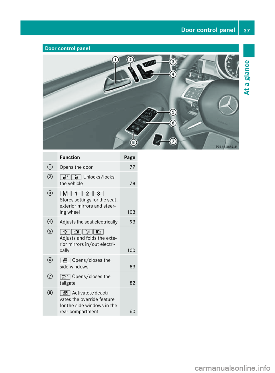
Door control panel
Function Page
:
Opens th
edoor 77
;
%&
Unlocks/locks
th ev ehicle 78
=
r4
5=
Stores se ttingsfor theseat,
exterior mirrors and steer-
ing wheel 103
?
Adjusts the seat electrically 93
A
7Zö\
Adjusts and folds the exte-
rio
rm irrors in/out electri-
cally 100
B
W
Opens/closes the
side windows 83
C
q
Opens/closes the
tailgate 82
D
n
Activates/deacti-
vates the override feature
for the side windows in the
rear compartment 60 Doo
rcontrol panel
37Atag lan ce
Page 95 of 389
Usefu
linfor mati on
i This Owner's Manual describes all models
and all standard and optional equipment
available to your vehicle at the time of pub-
lication of the Owner's Manual. Country-
specific deviation sare possible .Please
not ethat your vehicle ma ynot be equipped
with all featur es described. This also
applies to safety-releva ntsystems and
functions.
i Please read the information on qualified
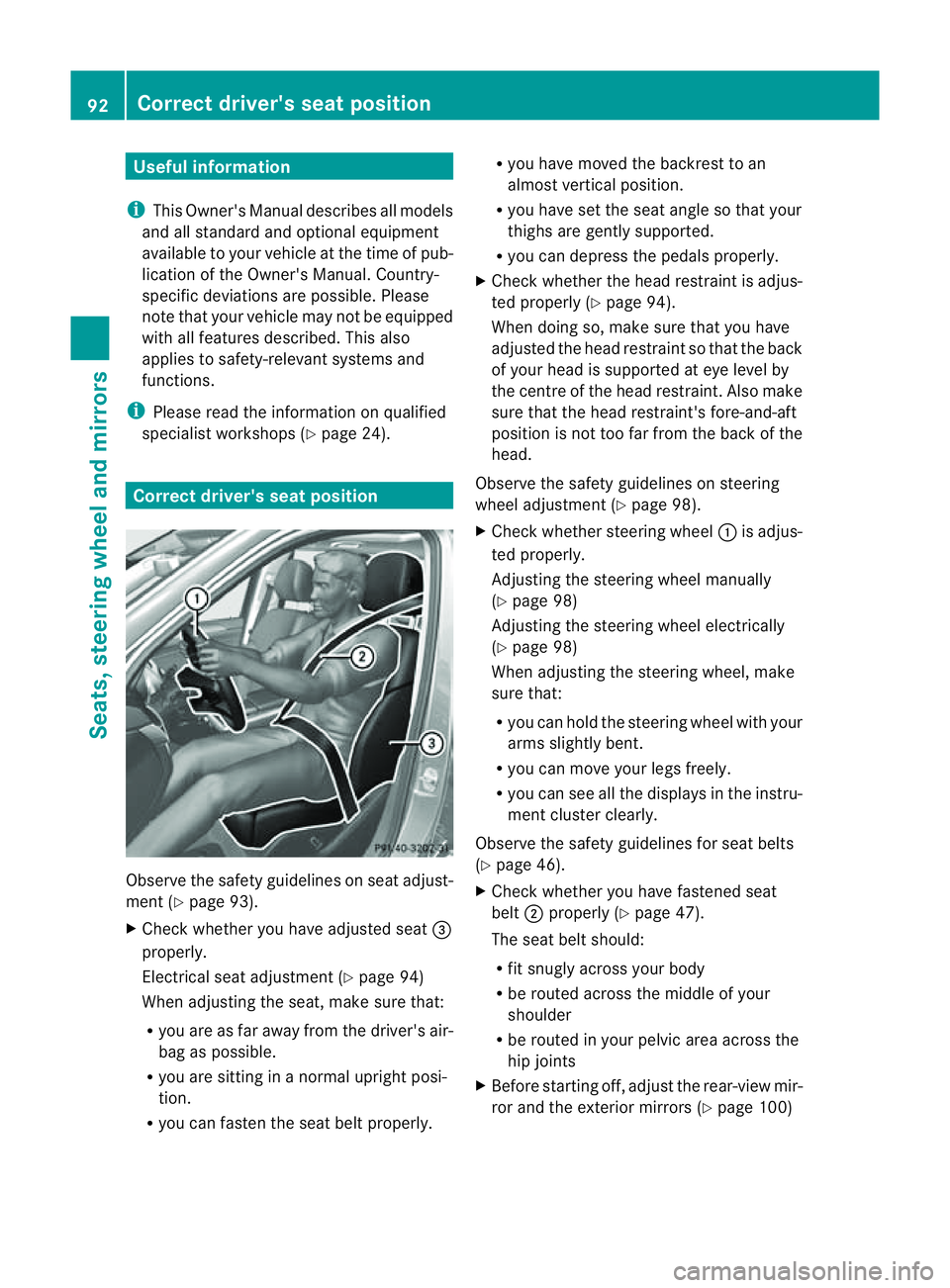
specialist workshops (Y page 24).Correct driver'
sseatp osition Observ
ethe safety guideli neso nseat adjust-
men t(Ypage 93).
X Chec kwhether you hav eadjusted seat =
properly.
Electrical seat adjustment (Y page 94)
When adjusting the seat, mak esure that:
R you are as far away from the driver' sair-
bag as possible.
R you are sitting in anormal upright posi-
tion.
R you can fasten the seat belt properly. R
you have moved the backrest to an
almost vertical position.
R you have set the seat angle so that your
thighs ar egently supported.
R you can depress the pedals properly.
X Check whether the head restraint is adjus-
ted properly (Y page 94).
When doing so, mak esure that you have
adjusted the head restraint so that the back
of your head is supported at eye level by
the centre of the head restraint .Also make
sure that the head restraint's fore-and-aft
position is not too far from the bac kofthe
head.
Observ ethe safety guidelines on steering
wheel adjustment (Y page 98).
X Chec kwhether steering wheel :is adjus-
ted properly.
Adjusti ngthe steering whee lmanually
(Y page 98)
Adjustin gthe steering wheel electrically
(Y page 98)
When adjustin gthe steering wheel, make
sur ethat:
R you can hold the steering wheel with your
arms slightl ybent.
R you can mov eyour legs freely.
R you can see all the displays in the instru-
men tcluster clearly.
Observe the safety guidelines for seat belts
(Y page 46).
X Check whether you have fastened seat
belt ;properly (Y page 47).
The seat belt should:
R fit snugly across your body
R be routed across the middle of your
shoulder
R be routed in your pelvic area across the
hip joints
X Befor estartin goff, adjus tthe rear-vie wmir-
ror and the exterior mirrors (Y page 100)92
Correct driver's seat positionSeats, steerin
gwhee land mirrors
Page 96 of 389
in such
away that you have agood view of
roa dand traffic conditions.
X Vehicles with amemory function: save
the seat, steerin gwheel and exterior mirror
settings (Y page 103). Sea
ts Important safety notes
G
WARNING
The seats can still be adjusted when ther eis
no key in the ignition lock. For this reaso n,
children shoul dnever be left unsupervised in
the vehicle. They could adjust the seat sand
become trapped. G
WARNING
Only adjus tthe driver' sseat when the vehicle
is stationary. You will otherwise be distrac ted
from the road and traffic conditions and you
could lose control of the vehicle as aresult of
the seat moving. This could cause an acci-
dent. G
WAR
NING
If you adjus tthe seat height car elessly, you or
others could be trapped and thereb yinjured.
Children in particular could unintentionally
pres sthe buttons to electrically adjust the
seat sand become trapped.
Take care that:
R whil emoving the seats, your hands do not
get under the lever assembly of the seat
adjustmen tsystem.
R children in the vehicl edonot slidetheir
hands unde rthe levers. G
WARNING
Make sur ethat nobody can becom etrapped
when adjusting the seats.
Observe the notes on airbags.
Secure children as recomm ended; see the
"Children in the vehicle" section. G
WAR
NING
Make sure that the back of your head is sup-
ported at eye level by the central area of the
head restraint .Ifyour head is not supported
correctly by the head restraint ,you coul dsuf-
fer asever eneck injury in the event of an
accident .Never driv eifthe head rest raints are
not engaged and set correctly. G
WARNING
As eat belt can only offer its intended degree
of protection when the back rest is almost ver-
tical and the occupan tiss itting upright. Avoid
seat positions that do not allow the seat belt
to be routed correctly. Adjust the backrest so
that it is as upright as possible .Never travel
with the back rest reclined too fa rbackwards.
You could otherwise be seriousl yoreven
fatally injured in th eevent of an accident or
sudden braking.
! To avoid damag etothe seats and the seat
heating, observe the followin ginformation:
R do not spill any liquids on the seats. If
liquid is spilled on the seats, dry them as
soon as possible.
R if the sea tcover sare damp or wet, do not
switc hont he seat heating. The seat
heating should also not to be used to dry
the seats.
R clea nthe seat cover sasrecommended;
see the "In terior care" section.
R do not transport heav yloads on the
seats. Do not plac eshar pobjects on the
seat cushions ,e.g. knives, nails or tools.
Th es eats should only be occupied by
passengers, if possible.
R when the seat heatin gisinoperation ,do
not cover the seats with insulating mate-
rials, e.g. blanke ts,c oats, bags, seat cov-
ers, child seats or booster seats.
! When you mov ethe seats, make sur ethat
ther eare no objects in th efootwell or
behind the seats. Otherwise, you could
damage the seats and the objects. Seats
93Seats,steering wheeland mirrors Z
Page 103 of 389
Position of th
esteerin gwheel for driv-
ing Th
es teering whee lismoved to the previously
set position if:
R the driver's door is closed.
R you inser tthe key int othe ignition lock.
or
R you press the Star t/Stop butto nonce on
vehicles with KEYLESS-GO.
If you clos ethe driver's door with the key
inserted int othe ignition lock ,the steering
wheel is automatically moved to the previ-
ously set position.
The last position of the steering wheel is
stored when you switc hoff th eignition or
when you stor ethe setti ngwith the memory
function (Y page 103).
Crash-responsive EASY-EXIT fea tureIf th
ecrash-resp onsive EASY-EXIT feature is
trig gere dinana ccident,the steeri ngcolu mn
will mov eupwards when the driv er'sdoor is
opened. This occurs irrespective of the posi-
tion of the key in the ignition lock .This makes
it easier to exit the vehicle and rescue the
occupants.
The crash-responsive EASY-EXIT featur eis
only operational if the EASY-EXIT/ENTRY fea-
tur eisa ctivate dinthe on-boar dcomputer. Mirrors
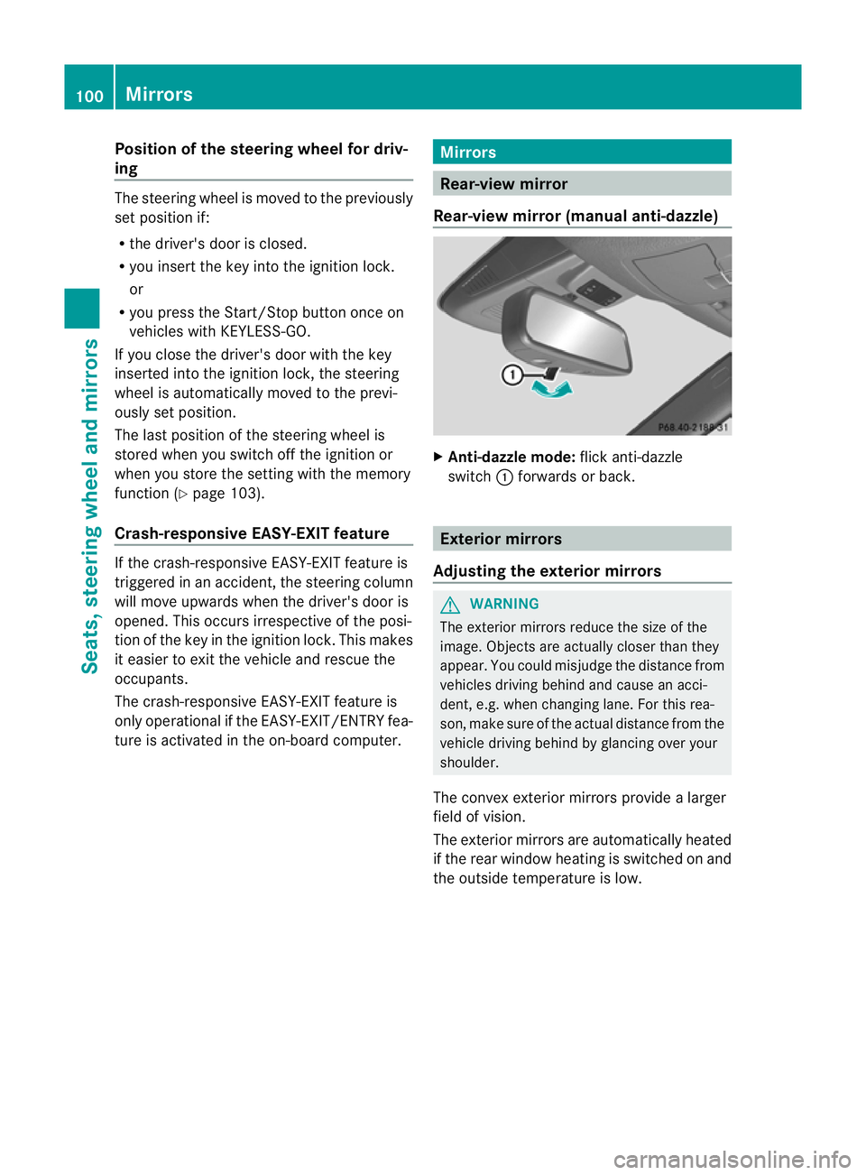
Rear-view mirror
Rear-view mirror (manua lanti- daz zle) X
Anti-dazzle mode: flick anti-dazzle
switch :forward sorback. Exterior mirrors
Adjusting the exterior mirrors G
WARNING
The exterior mirrors reduce the size of the
image. Objects are actually closer than they
appear. You could misjudge the distance from
vehicles driving behind and cause an acci-
dent, e.g. when changing lane. For this rea-
son, make sure of the actual distance from the
vehicle driving behind by glancing over your
shoulder.
The convex exterior mirrors provide alarger
field of vision.
The exterior mirrors are automatically heated
if the rear window heating is switched on and
the outside temperature is low. 100
MirrorsSeats
,steering wheel and mirrors
Page 104 of 389
X
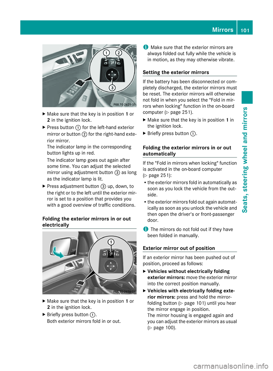
Make sur ethat the key is in position 1or
2 in the ignition lock.
X Press button :for the left-hand exterior
mirror or button ;for the right-hand exte-
rior mirror.
The indicator lam pint he corresponding
button lights up in red.
The indicator lam pgoes out again after
some time. You can adjust the selected
mirror using adjustment button =as long
as the indicator lam pislit.
X Press adjustment button =up, down, to
the right or to the left until the exterior mir-
ror is set to aposition that provides you
with agood overview of traffic conditions.
Folding th eexterior mir rors in or out
electrically X
Make sure that the key is in position 1or
2 in the ignitio nlock.
X Briefl ypres sbutton :.
Both exterior mirrors fold in or out. i
Make sure that the exterior mirrors are
always folded out fully while the vehicle is
in motion, as they may otherwis evibrate.
Setting the exterior mirrors If the battery has been disconnected or com-
pletely discharged, the exterior mirrors must
be reset. The exterior mirrors will otherwise
not fold in when you select the "Fold in mir-
rors when locking" func tion in the on-board
computer (Y page 251).
X Make sure that the key is in position 1in
the ignition lock.
X Briefl ypres sbutton :.
Folding the exterior mirrors in or out
automatically If the "Fold in mirrors when locking" function
is activated in the on-board computer
(Y page 251):
R the exterior mirrors fold in automatically as
soo nasyou lock the vehicle from the out-
side.
R the exterior mirror sfold out again automat-
ically as soon as you unloc kthe vehicle and
then open the driver's or front-passenger
door.
i The mirrors do not fol dout if they have
been folded in manually.
Exterior mirror out of position If an exterior mirror has been pushed out of
position, proceed as follows:
X Vehicles without electrically folding
exterior mirrors: move the exterior mirror
into the correct position manually.
X Vehicles with electrically folding exte-
rior mirrors: press and hold the mirror-
folding button (Y page 101)until you hear
the mirror engage in position.
The mirror housing is engaged agai nand
you can adjus tthe exterior mirrors as usual
(Y page 100). Mir
rors
101Seats ,steeri ngwheel and mirrors Z
Page 105 of 389
Automati
canti-dazzle mirrors G
WA
RNING
If inciden tlight fro mheadlamps is prevented
from striking the sensor in the rear-view mir-
ror ,for instance, by luggage piled too high in
the vehicle, the mirror's automatic anti-dazzle
fun ction will not operate.
Incident light could then blind you. This may
distrac tyou from the traffic condition sand,
as aresult, you may cause an accident.
The rear-view mirror and the exterior mirror
on the driver' sside automatically go into anti-
dazzle mode if the ignition is switched on and
inciden tlight from headlamps strikes the sen-
sor in the rear-view mirror.
The mirror sdonot go int oanti-dazzle mode if
reverse gea risengaged or if the interior light-
ing is switched on. Parking position for the exterior mir-
ror on the front-passenge rside
Setting and storing the parking position You can position the front-passenger side
exterior mirror in such away that you can see
the rear wheel on that side as soon as you
engage revers egear. You can stor ethis posi-
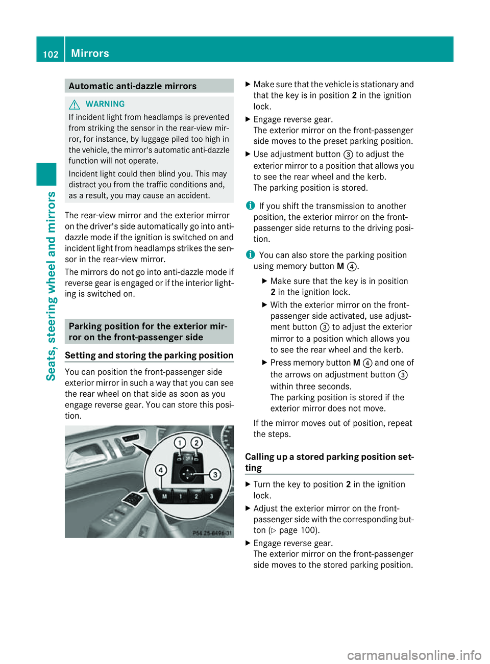
tion. X
Make sur ethat the vehicle is stationary and
that the key is in position 2in the ignition
lock.
X Engage revers egear.
The exterior mirror on the front-passenger
side moves to the preset parkin gposition.
X Use adjustment button =to adjust the
exterior mirror to aposition that allows you
to see the rea rwheel and the kerb.
The parkin gposition is stored.
i If you shift the transmission to anot her
po sition ,the exterior mirror on the front-
passenger side retur nsto the driving posi-
tion.
i You can also store the parking position
using memory button M?.
X Make sure that the key is in position
2in the ignitio nlock.
X With the exterior mirror on the front-
passenger side activa ted, use adjust-
ment button =to adjust the exterior
mirror to aposition which allows you
to see the rea rwheel and the kerb.
X Press memory button M? and one of
the arrow sonadjustment button =
within three seconds.
The parkin gposition is stored if the
exterior mirror does not move.
If the mirror moves out of position ,repeat
the steps.
Calling up astore dparkin gposition set-
ting X
Turn the key to position 2in the ignition
lock.
X Adjus tthe exterior mirror on the front-
passenger side with the correspondin gbut-
ton (Y page 100).
X Engage reverse gear.
The exterior mirror on the front-passenger
side moves to the stored parking position. 102
MirrorsSeats, steerin
gwhee land mirrors
Page 106 of 389
The exterior mirror on the front-passenger
side moves back to its original position:
R
as soon as you exceed aspeed of
15 km/h
R about ten seconds after you have disen-
gaged reverse gear
R if you press button :for the exterior mir-
ror on the driver' sside Memory function
Storing settings
With the memor yfunction, you can store up
to three different settings, e.g. for three dif-
ferent people.
The following settings are stored as asingle
memor ypreset:
R positio nofthe seat, backrest and head
rest raint
R driver's side: steerin gwheel position
R driver's side: position of the exterior mir-
ror sont he driver's and front-passenger
sides G
WARNING
The memory func tion can still be used when
the key has been removed. For this reason,
children should never be left unsupervised in
the vehicle. They coul dotherwis ebecome
trapped when adjusting the seat or the steer-
ing wheel. G
WARNING
Only use the memory function on the driver's
side when the vehicle is stationary .Other-
wise ,you coul dbedistracted from the traf fic
conditions by the steering wheel and seat
moving of their own accord ,and as aresult
cause an accident. X
Adjust the seat (Y page 94).
X On the driver' sside, adjust the steering
wheel (Y page 98) and the exterior mirrors
(Y page 100).
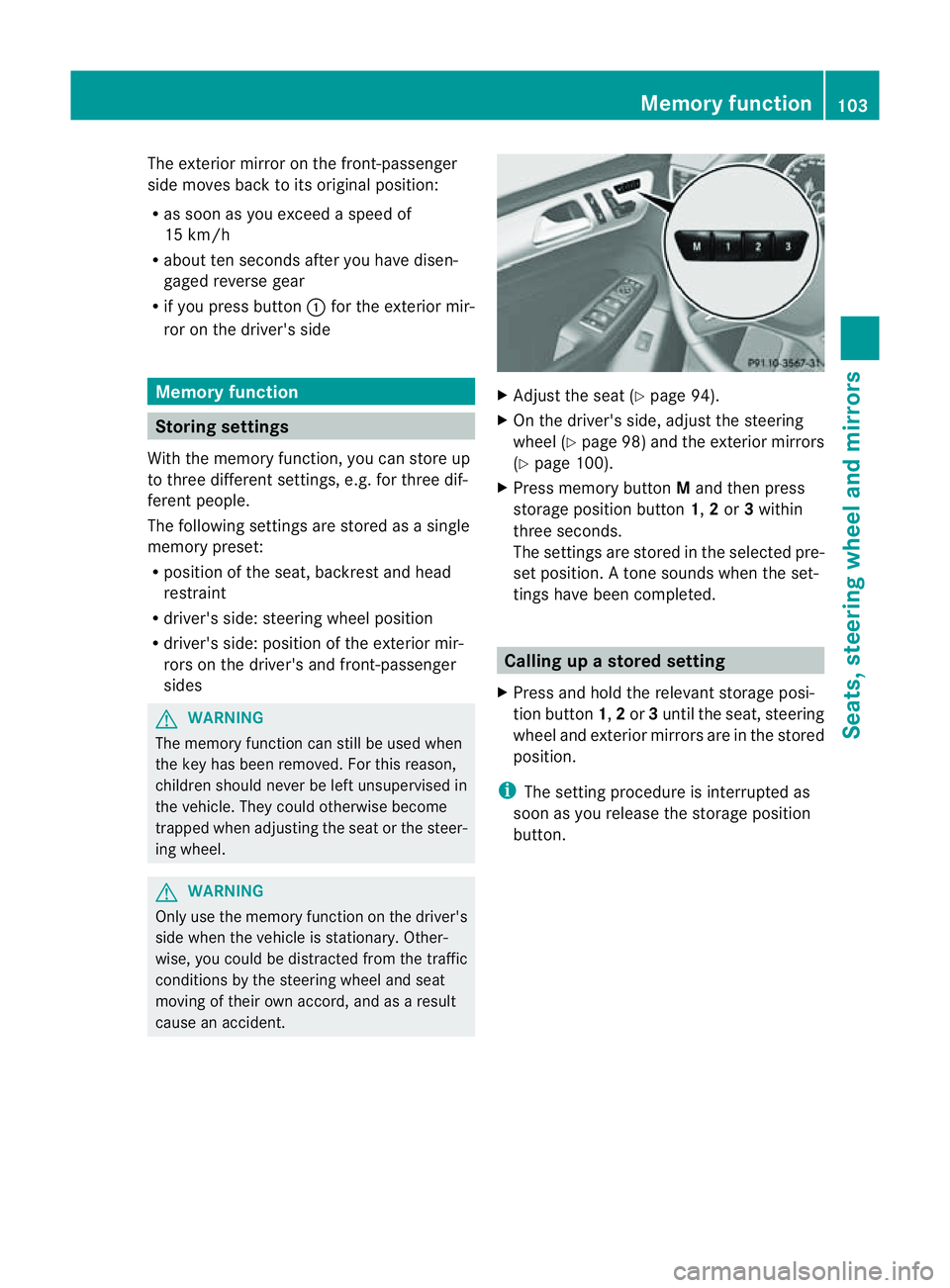
X Press memor ybutton Mand then press
storage position button 1,2or 3within
three seconds.
The settings are stored in the selected pre-
set position. Atone sounds when the set-
tings have been completed. Calling up
astore dsetting
X Pres sand hol dthe rele vant storage posi-
tion button 1,2or 3until the seat ,steering
wheel and exterio rmirror sare in th estored
position.
i The settin gprocedure is interrup tedas
soon as you release the storage position
but ton. Memory function
103Seats,steering wheeland mirrors Z
Page 202 of 389
tion. See the separate COMAND operating
instructi
ons.
The symbo lofthe selected function is high-
lighted.
To deactivate: the reversing camera is deac-
tivated if you:
R shift the transmission to position P
R drive forward ten metres
R shift the transmission from position Rto
anothe rposition (after 15 seconds)
R drive forwards at aspeed of over
10 km/h
Displays in the COMAN Ddisplay G
WARNING
Usin gthe reversing camera can be dangerous
if you ar ecolour-blin dorify our ability to dis-
tinguish colours is impaired.
Only use the reversin gcamera if you can see
and distinguis hbetween all the coloured
guide lines that are displayed by the reversing
camera in the COMAN Ddisplay. G
WARNING
Please note that objects not at ground level
may appea rtobefurther away than they
actually are. Thes einclude:
R the bumper of avehicle that is parked
behind your vehicle
R at railer drawbar
R theb all coupling of atrailer tow hitch
R thet ail-end of alorry
R slanted posts
The lines are only guides, not accurate meas-
urements of the distance to an obstacle.
Therefore, you should never pass the red line
when approachin ganobstacle. You could oth-
erwise cause an accident and injur eyourself
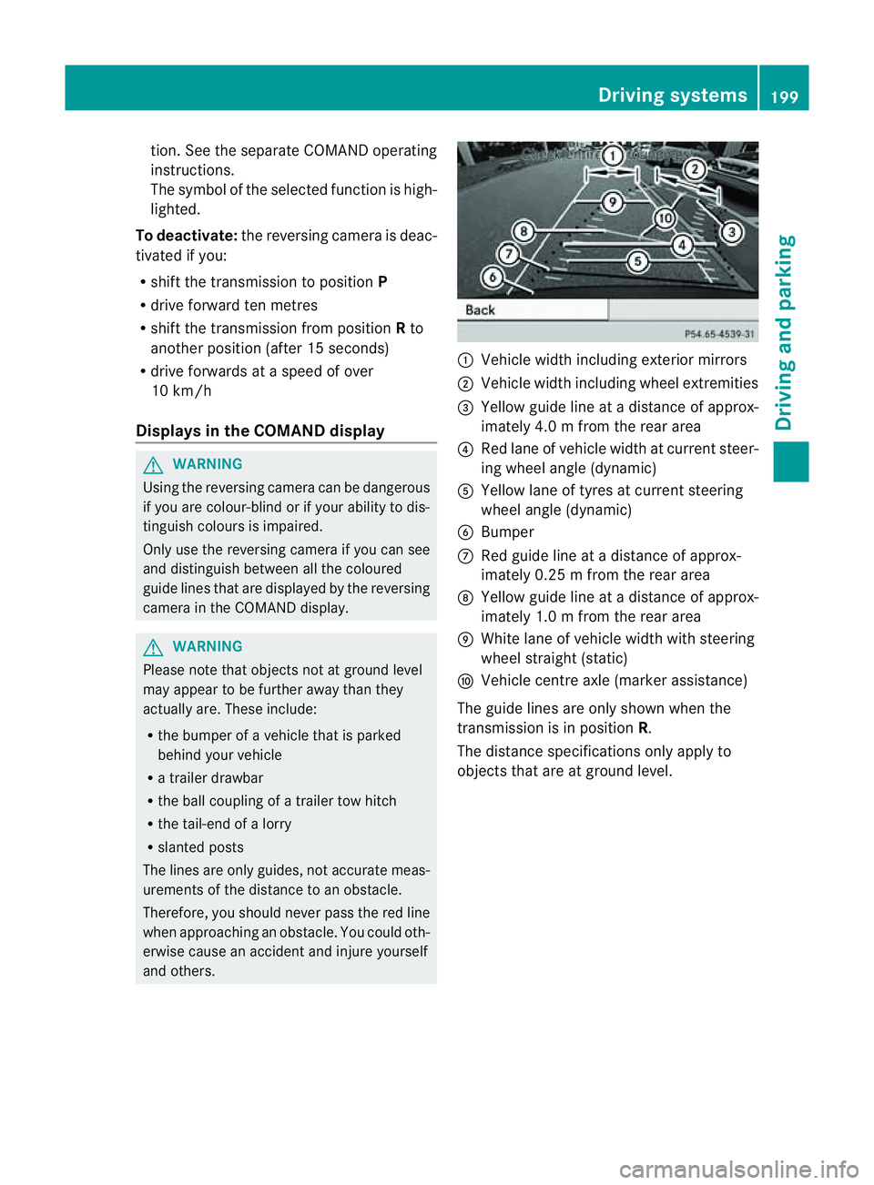
and others. :
Vehicle width includin gexterior mirrors
; Vehicl ewidth including wheel extremities
= Yellow guide line at adistance of approx-
imately 4.0 mfrom th erear area
? Red lane of vehicle width at curren tsteer-
ing whee langle (dynamic)
A Yellow lane of tyres at current steering
wheel angle (dynamic)
B Bumper
C Red guid eline at adistance of approx-
imately 0.2 5mfrom th erear area
D Yellow guide line at adistance of approx-
imately 1.0 mfrom th erear area
E White lane of vehicle width with steering
wheel straight (static)
F Vehicle centre axle (marker assistance)
The guide lines are only shown when the
transmission is in position R.
The distance specification sonly appl yto
objec tsthat are at ground level. Driving systems
199Drivingand park ing Z