service MERCEDES-BENZ METRIS 2016 MY16 Operator’s Manual
[x] Cancel search | Manufacturer: MERCEDES-BENZ, Model Year: 2016, Model line: METRIS, Model: MERCEDES-BENZ METRIS 2016Pages: 310, PDF Size: 7.28 MB
Page 247 of 310
!Take care not to spill any coolant on painted
surfaces. You could otherwise damage the
paintwork.
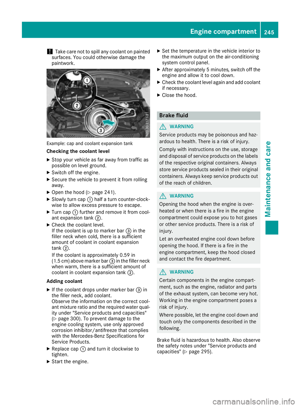
Example: cap and coolant expansion tank
Checkingt he coolant level
XStop your vehicle as far awayf rom traffic as
possible on level ground.
XSwitch off the engine.
XSecure the vehicle to prevent it from rolling
away.
XOpen the hood (Ypage 241).
XSlowly turn cap :half aturn counter-clock-
wise to allow excess pressure to escape.
XTurn cap :further and remove it from cool-
ant expansion tank ;.
XCheck the coolant level.
If the coolant is up to marker bar =in the
filler neck when cold, there is asufficient
amount of coolant in coolant expansion
tank ;.
If the coolant is approximately 0.59 in
(1.5 cm) above marker bar =in the filler neck
when warm, there is asufficient amount of
coolant in coolant expansion tank ;.
Adding coolant
XIf the coolant drops under marker bar =in
the filler neck, add coolant.
Observe the information on the correct cool-
ant mixture ratio and the required water qual-
ity under "Service products and capacities"
(
Ypage 300). To prevent damage to the
engine cooling system, use only approved
corrosion inhibitor/antifreeze that complies
with the Mercedes-Benz Specifications for
Service Products.
XReplace cap :and turn it clockwise to
tighten.
XStart the engine.
XSet the temperature in the vehicle interior to
the maximum output on the air-conditioning
system control panel.
XAfter approximately 5minutes ,switch off the
engine and allow it to cool down.
XCheck the coolant level againa nd add coolant
if necessary.
XClose the hood.
Brake fluid
GWARNING
Service products may be poisonous and haz-
ardous to health. There is arisk of injury.
Comply with instructionsont he use, storage
and disposalofs ervice products on the labels
of the respective original containers. Always
store service products sealed in their original
containers. Alwaysk eep service products out
of the reach of children.
GWARNING
Opening the hood when the engine is over-
heated or when there is afire in the engine
compartment could expose you to hot gases
or other service products. There is arisk of
injury.
Let an overheated engine cool down before
opening the hood. If there is afire in the
engine compartment,k eep the hood closed
and contact the fire department.
GWARNING
Certain componentsint he engine compart-
ment, such as the engine, radiator and parts
of the exhaust system, can become very hot.
Working in the engine compartment poses a
risk of injury.
Where possible,l et the engine cool down and
touch only the componentsd escribed in the
following.
Brake fluid is hazardous to health. Also observe the safety notes under "Service products and
capacities" (
Ypage 295).
Engine compartment245
Maintenance and care
Z
Page 248 of 310
GWARNING
The brake flui dconstantly absorbs moisture
from the air. This lowers the boiling point of
the brake fluid. If the boiling point of the brake
flui dist oo low ,vapo rpockets may form in the
brake system when the brakes are applied
hard .This would impair braking efficiency.
There is arisk of an accident.
You should have the brake flui drenewe dat
the specified intervals.
!If the brake flui dlevelint he brake flui dres-
ervoir has fallen to the MIN mark or below,
check the brake system immediatel yfor
leaks. Also check the thickness of the brake
linings. Visi taqualified specialist workshop
immediately.
Do not add brake fluid. This does not correct
the malfunction.
!Brake flui dcorrodes paint, plastic and rub-
ber. If paint, plastic or rubber has come into
contact with brake fluid, rinse with water
immediately.
Have the brake flui drenewe devery 2years at a
qualified specialist workshop. Observe the infor-
mation regarding brake flui dinthe "Service
products and capacities" section (
Ypag e300).
Check the brake flui dlevelr egularly, e.g. weekly
or when refueling.
Checking the brake fluid level
XStop you rvehicl easf ar awa yfrom traffic as
possible on leve lground.
XSwitch off the engine.
XSecure the vehicletop revent it from rolling
away.
XOpen the hood (Ypag e241).
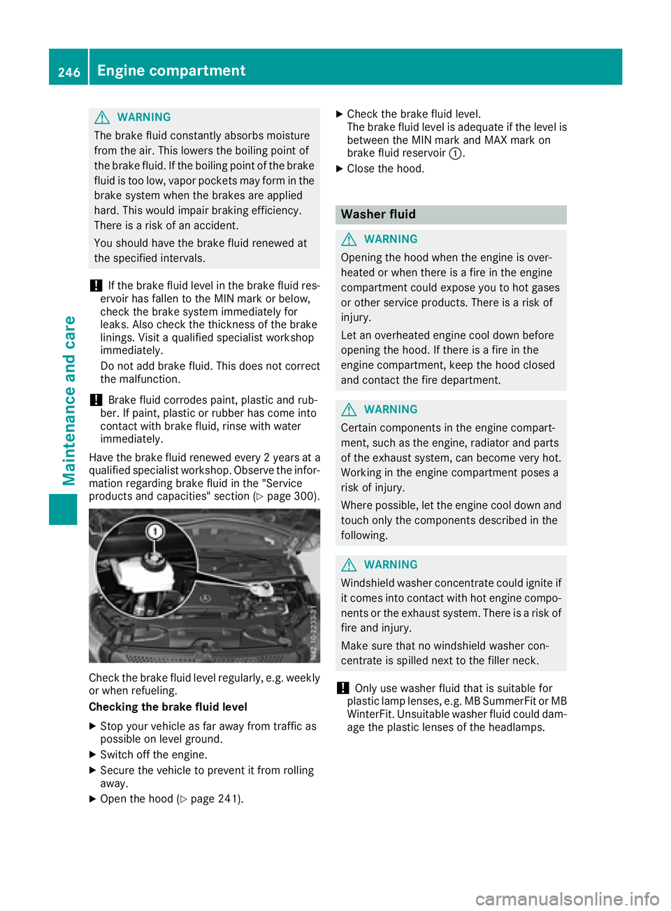
XCheck the brake flui dlevel.
The brake flui dlevelisa dequate if the leve lis
between the MIN mark and MAX mark on
brake flui dreservoir :.
XClose the hood.
Washer fluid
GWARNING
Opening the hood when the engine is over-
heated or when there is afire in the engine
compartment coul dexpose you to hot gases
or other service products. There is arisk of
injury.
Let an overheated engine cool downb efore
opening the hood. If there is afire in the
engine compartment, keep the hood closed
and contact the fire department.
GWARNING
Certain components in the engine compart-
ment, such as the engine, radiator and parts
of the exhaust system, can become very hot.
Working in the engine compartment poses a
risk of injury.
Where possible,l et the engine cool downa nd
touch only the components described in the
following.
GWARNING
Windshiel dwasher concentrate coul dignite if
it comes into contact with hot engine compo-
nents or the exhaust system. There is arisk of
fire and injury.
Make sure that no windshiel dwasher con-
centrate is spilled next to the filler neck.
!Only use washer flui dthat is suitable for
plastic lamp lenses ,e.g. MB SummerFi torMB
WinterFit. Unsuitable washer flui dcoul ddam-
age the plastic lenses of the headlamps.
246Engine compartment
Maintenance and care
Page 249 of 310
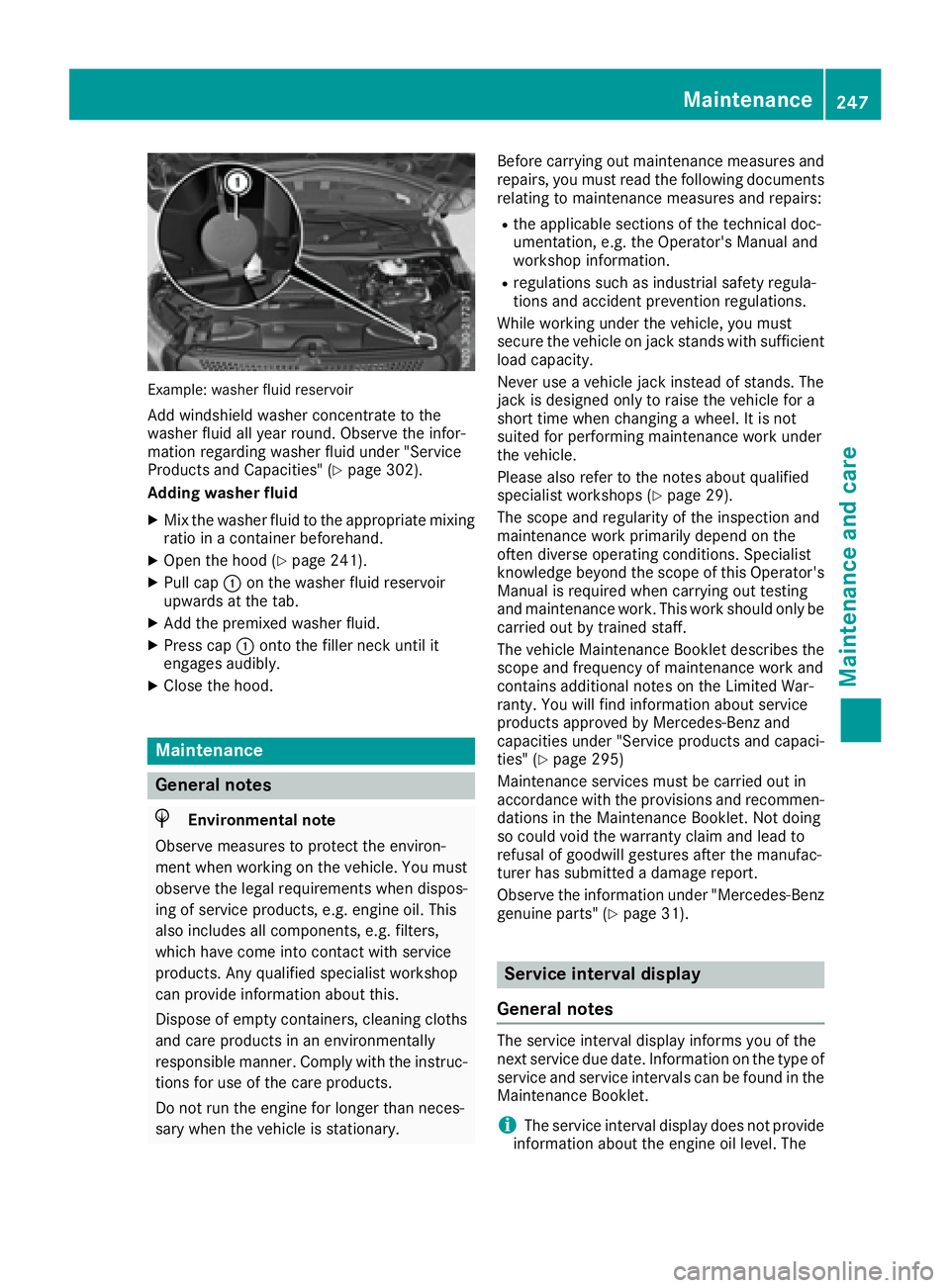
Example: washerfluid reservoir
Add windshield washe rconcentrate to the
washe rfluid al lyea rround. Observ ethe infor-
matio nregarding washe rfluid under "Service
Products and Capacities" (
Ypage 302).
Adding washe rfluid
XMixt he washe rfluid to the appropriate mixing
ratio in acontaine rbeforehand.
XOpe nthe hoo d(Ypage 241).
XPull cap :on the washe rfluid reservoir
upwards at the tab.
XAdd the premixe dwashe rfluid.
XPress cap :onto the fille rneck unti lit
engages audibly.
XClose the hood.
Maintenance
General notes
HEnvironmental note
Observ emeasures to protect the environ-
ment when working on the vehicle. Yo umust
observe the legalr equirements when dispos-
ing of servic eproducts, e.g .engine oil. This
also includes al lcomponents, e.g .filters,
which have come into contact with service
products. Any qualified specialist workshop
can provid einformatio nabout this.
Dispose of empty containers, cleaning cloths
and car eproducts in an environmentally
responsibl emanner. Compl ywitht he instruc-
tions for us eofthe car eproducts.
Do not runt he engine for longert hanneces-
sary when the vehicl eisstationary. Before carrying outm
aintenance measures and
repairs, yo umustrea dt he following documents
relating to maintenance measures and repairs:
Rthe applicabl esections of the technica ldoc-
umentation, e.g .the Operator' sManualand
workshop information.
Rregulations such as industria lsafety regula-
tions and accident prevention regulations.
While working under the vehicle, yo umust
secur ethe vehicl eonjack stands with sufficient
load capacity.
Never us eavehicl ejack instea dofstands. The
jack is designe donlytor aisethe vehicl efor a
short time when changing awheel .Itisn ot
s ui
te df or performing maintenance work under
the vehicle.
Please also refer to the notesa boutqualified
specialist workshops(
Ypage 29).
The scop eand regularity of the inspectio nand
maintenance work primaril ydepen dont he
ofte ndiverse operating conditions. Specialist
knowledg ebeyond the scop eofthisOperator's
Manua lisrequired when carrying outt esting
and maintenance work. Thi sworks houl donlyb e
carrie doutby trained staff.
The vehicl eMaintenance Bookle tdescribe sthe
scop eand frequency of maintenance work and
contains additional notes on the Limite dWar-
ranty. Yo uwillf ind informatio nabout service
products approved by Mercedes-Benz and
capacitie sunder "Service products and capaci-
ties" (
Ypage 295)
Maintenance services must be carrie doutin
accordance with the provisions and recommen-
dations in the Maintenance Booklet. Not doing
so could voi dthe warranty claim and lead to
refusal of goodwil lgestures afte rthe manufac-
turer hass ubmitted adamag ereport.
Observ ethe informatio nunder "Mercedes-Benz
genuine parts" (
Ypage 31).
Service interval display
General notes
The servic eintervald isplay informs yo uofthe
next servic eduedate. Informatio nonthe typ eof
servic eand servic eintervals can be found in the
Maintenance Booklet.
iThe servic eintervald isplay does not provide
informatio nabout the engine oill evel.T he
Maintenance247
Maintenance and care
Z
Page 250 of 310
service interval displayshould therefore not
be confused with the engine oil level display.
For example, the displays hows one of the fol-
lowing service messages for afew seconds:
RNext Service Ain..Days
RServiceADueorService ADue
RServ. AExceed. by .. Days
Then either the remaining time or distance until
the next service due date is displayed. If the
service due date has been exceeded, the
elapsedt ime or distance traveled after the over-
due service date is shown. The letter in the dis-
play message indicates which service is due. A
stands foraminor service and Bforam ajor ser-
vice.
Aq ualified specialist workshop, e.g. an author-
ized Mercedes-Benz Commercial Van Center,
will reset the service interval displaya fter the
service work has been carried out. You can also
obtain further information on maintenance
work, for example.
The prescribed service interval is based on nor- mal vehicle use. Service work will need to be
performed more frequently than prescribed if
the vehicle is operated under more arduousc on-
ditions or with higher loads. Such arduousc on-
ditions include:
Rregularc ity driving with frequent intermediate
stops
Rdriving predominantly short distances
Rfrequent operation in mountainous terrain or
on poor road surfaces
Rleaving the engine idling for long periods on a frequent basis
In these or similar operating conditions, have
the air filter, engine oil and oil filter, for example,
replaced more frequently. Under more arduous
operating conditions, the tires must be checked more often. Further information can be obtained
at aq ualified specialist workshop, e.g. an
authorized Mercedes-Benz Commercial Van
Center.
Hiding service messages
Vehicles without steering wheel buttons
XPress the 3button on the instrument clus-
ter.
Vehicles with steering wheel buttons
XPress the aor% button on the steering
wheel.
Callingupt he service due date
Vehicles without steering wheel buttons
The vehicle must be stationary. Use the buttons
in the instrument cluster.
XTurn the key to position 2in the ignition lock.
XPress Èto select the service display.
The displays howsapossible service mes-
sage.
Vehicles with steering wheel buttons
Using the steering wheel buttons
XTurn the key to position 2in the ignition lock.
XPress =or; to select the Servicemenu.
XPress the9or: button to select the
ASSYST PLUSsubmenu and press ato
confirm.
The displays hows the service due date.
Battery
Important safety notes
Work on the battery, e.g. removing or installing,
requires specialist knowledge and the use of
special tools. Therefore, always have work on
the battery carried out at aqualified specialist
workshop.
GWARNING
Work carried out incorrectly on the battery
can lead, for example, to ashort circuit and
thus damage the vehicle electronics. This can
lead to function restrictions applying to
safety-relevant systems, e.g the lighting sys-
tem, the ABS (anti-lock braking system) or the
ESP
®(Electronic Stability Program). The oper-
ating safety of your vehicle may be restricted.
You could lose control of the vehicle, for
example:
Rwhen braking
Rin the event of abrupt steering maneuvers
and/or when the vehicle's speed is not
adapted to the road conditions
There is arisk of an accident.
In the event of ashort circuit or asimilari nci-
dent, contact aqualified specialist workshop
248Battery
Maintenance and care
Page 251 of 310
immediately. Do not drive any further. You
should have all work involvingthe battery car-
ried out at aqualified specialist workshop.
Further information can be foundu nder "ABS"
(
Ypage 62) and under "ESP®"(Ypage 64).
GWARNING
Electrostatic build-up can lead to the creation of sparks, which could ignit ethe highly explo-
sive gases of abattery. There is arisk of an
explosion.
Before handlin gthe battery, touc hthe vehicle
body to remove any existin gelectrostatic
build-up.
The flammable gas mix is produced when the
battery is charged or when the vehicle is jump-
started.
Always make sure that neither you nor the bat-
ter ya re electro statically charged. Electrostatic
charging results, for example, from:
Rwearings ynthetic clothing
Rfriction betwee nclothing and the seat
Rdraggingorp ushingthe battery across carpet
flooring or any other synthetic materials
Rrubbingt he battery with cloths or towels.
Comply with the followings afetyprecautions
and tak eprotective measuresw hen handling
batteries.
Risk of explosion.E xplosive oxyhy-
drogen is produced when batteries
are being charged. Only charge bat-
teries in well-ventilated areas.
Fire ,open flames and smoking are
therefore prohibited when working
on the battery. Avoid creating
sparks.
Batter yacid is caustic. Avoid con-
tac twith the skin ,eyes or clothing.
Wear acid-proof protective gloves.I f
skin or clothes are splashed with
acid, neutralize the splashes imme-
diately with soapy water or an acid
neutralizer, and the nclean the affec-
ted areas with water .Consult adoc-
tor if necessary.
Wear eye protection. When mixing
water and acid, the liquid can splash
int oy our eyes. Rinse acid splashes
to the eyes immediately with clean water and contac
tadoctor immedi-
ately.
Keep children at asafe distance.
Children are not able to assess the
danger sposed by batteries and
acid.
When handlin gbatteries, observe
the safetyp recautionsand special
protective measuresc ontained in
this Operator's Manual.
HEnvironmental note
Batteries contain dangerous
substances. It is against the
law to dispose of the mwith
the household rubbish. They
must be collected separately and recycled to protect the
environment.
Dispose of batteries in an
environmentally friendly
manner. Take discharged
batteries to aqualified spe-
cialist workshop or aspecial
collection point for used bat-
teries.
Observe the followingn otes:
RRecharge the battery more frequently, if you:
-predominantly drive shortd istances
-predominantly drive at low outside temper-
atures
-leave the vehicle parked for alengthy
period
In order for the batteries to achiev etheir max-
imum possible service life, the ymust always
be sufficiently charged.
RConsult an authorized Mercedes-Ben zCom-
mercial Van Center if you wish to leave your
vehicle parked for along period of time.
RWhen you park the vehicle, remove the Smart-
Key if you do not require any electrical con-
sumers. The vehicle will the nuse very little
energy, thus conserving battery power.
RIf your vehicle requiresj ump-starting, or if you
wish to provide jump-startin gassistanc eto
another vehicle, only use the jump-starting
Battery249
Maintenance and care
Z
Page 264 of 310
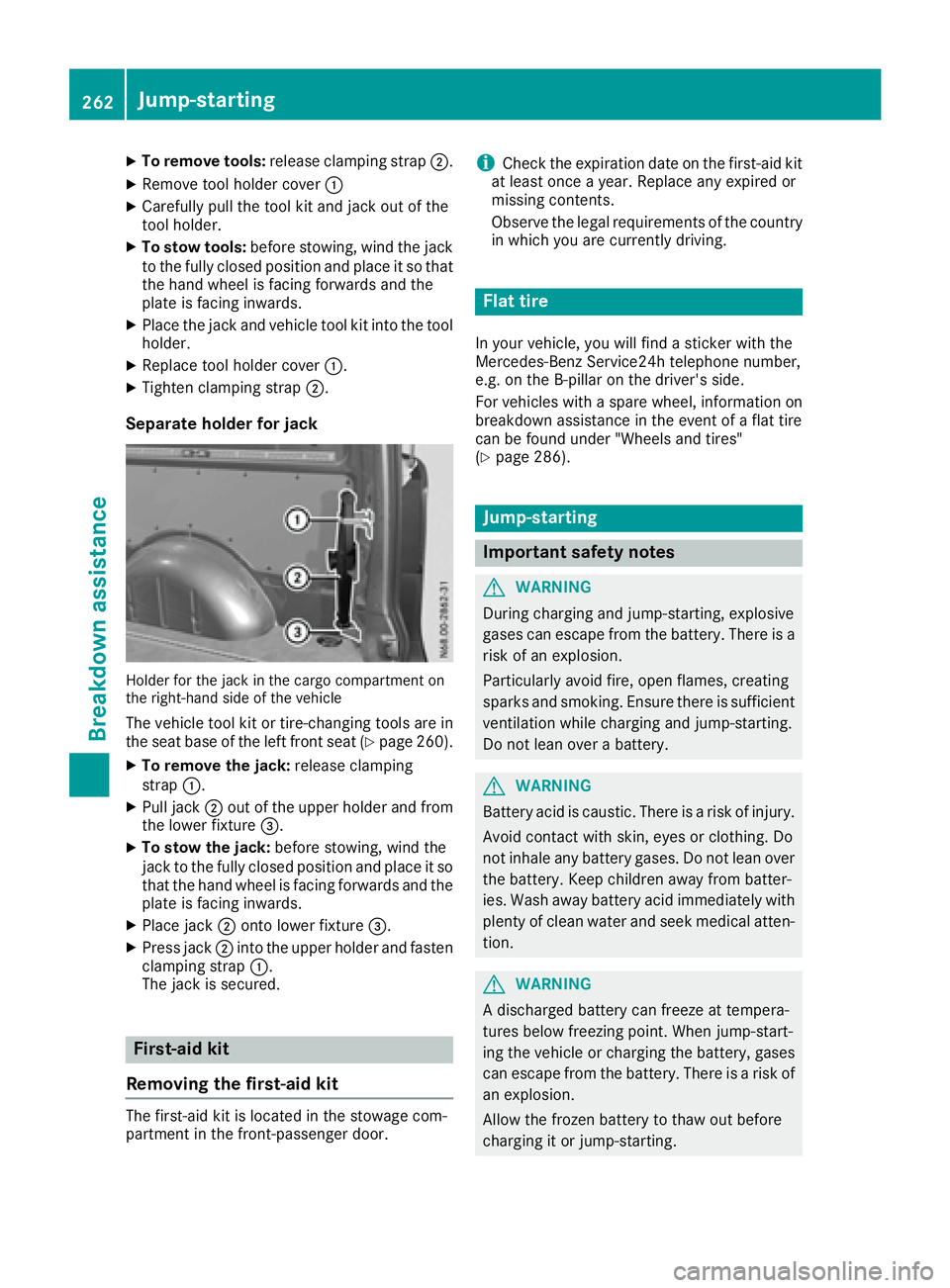
XTo remove tools:release clamping strap ;.
XRemove tool holdercover :
XCarefull ypullt he tool kit and jack outoft he
tool holder.
XTo stowt ools:before stowing ,windt he jack
to the fully closed positio nand place it so that
the hand whee lisfacing forward sand the
plate is facing inwards.
XPlace the jack and vehicl etool kit into the tool
holder.
XReplace tool holde rcover :.
XTighte nclamping strap ;.
Separate holder for jack
Holderfor the jack in the cargo compartment on
the right-hand side of the vehicle
The vehicl etool kit or tire-changing tool sare in
the sea tbaseoft he left front sea t(Ypage 260).
XTo remove the jack: release clamping
strap :.
XPull jack ;outoft he uppe rholde rand from
the lowe rfixture =.
XTo stowt he jack:before stowing ,windt he
jack to the fully closed positio nand place it so
thatt he hand whee lisfacing forward sand the
plate is facing inwards.
XPlace jack ;onto lowe rfixture =.
XPress jack ;into the uppe rholde rand fasten
clamping strap :.
The jack is secured.
First-ai dkit
Removing the first-aid kit
The first-aid kit is locate dinthe stowag ecom-
partment in the front-passenger door.
iCheck the expiratio ndateont he first-aid kit
at leas tonce ayear. Replace any expire dor
missing contents.
Observe the legalr equirements of the country
in which yo uare currentl ydriving.
Flat tire
In your vehicle, yo uwillf ind asticker with the
Mercedes-Benz Service24h telephone number,
e.g .ont he B-pillar on the driver' sside.
For vehicles with aspare wheel, informatio non
breakdowna ssistance in the event of aflatt ire
can be found under "Wheels and tires"
(
Ypage 286).
Jump-starting
Important safety notes
GWARNING
During charging and jump-starting ,explosive
gases can escape from the battery .There is a
ris kofane xplosion.
Particularly avoid fire, open flames ,creating
sparks and smoking .Ensure ther eissufficient
ventilatio nwhile charging and jump-starting.
Do not lean ove rabattery.
GWARNING
Battery aci discaustic .There is ariskofi njury.
Avoi dcontact with skin, eyes or clothing. Do
not inhal eany battery gases .Donot lean over
the battery .Keepc hildren away from batter-
ies. Wash away battery aci dimmediatelyw ith
plenty of clean water and see kmedica latten-
tion.
GWARNING
Ad ischarge dbattery can freeze at tempera-
ture sbelow freezing point. Whe njump-start-
ing the vehicl eorcharging the battery ,gases
can escape from the battery .There is arisko f
an explosion.
Allow the froze nbattery to thawo utbefore
charging it or jump-starting.
262Jump-starting
Breakdo wn assis tance
Page 265 of 310
!Vehicles withagasolinee ngine:avoid
repeated and lengthy starting attempts. Oth-
erwise, the catalytic converter could be dam-
aged by non-combusted fuel.
If the indicator and warning lamps in the instru-
ment cluster do not light up at low tempera-
tures, the discharged battery may have frozen.
In this case you may neither charge the battery
nor jump-start the vehicle. The service life of a
thawed battery may be shorter. Start-up behav-
ior may deteriorate, in particular at low temper-
atures. Have the thawed battery checked at a
qualified specialist workshop.
Do not use arapid charging device to start the
vehicle. If your vehicle's battery is discharged,
the engine can be jump-started from another
vehicle or from adonor battery using jumper
cables. For this purpose, the vehicle has ajump-
starting connection point in the engine com-
partment.
When jump-starting, observe the following
points:
RThe battery is not accessible in all vehicles. If
the other vehicle's battery is not accessible,
jump-start the vehicle using adonor battery
or ajump-startingd evice.
RYou may only jump-start the vehicle when the
engine and exhaust system are cold.
RDo not start the engine if the battery is frozen.
Let the battery thaw first.
RJump-starting may only be performed from
batteries with anominal voltage of 12 V.
ROnly use jumper cables that have asufficient
cross-section and insulated terminal clamps.
RIf the battery is fully discharged, attach the
battery of another vehicle for afew minutes
before attempting to start. This charges the
empty battery alittle.
RMake sure that the two vehicles do not touch.
Make sure that:
Rthe jumper cables are not damaged.
Rbare parts of the terminal clamps do not come
into contact with other metal parts while the
jumper cables are connected to the battery.
Rthe jumper cables cannot come into contact
with parts such as the V-belt pulley or the fan.
These parts move when the engine is started
and while it is running.
Jumper cables and further information regarding
jump starting can be obtained at any qualified
specialist workshop.
Before connecting the jumper cables
XApply the parking brake.
XShift the transmission to position P.
XSwitch off all electrical consumers, e.g. audio
equipment, blower.
XTurn key to position 0in the ignition lock and
remove it.
XOpen the hood (Ypage 241).
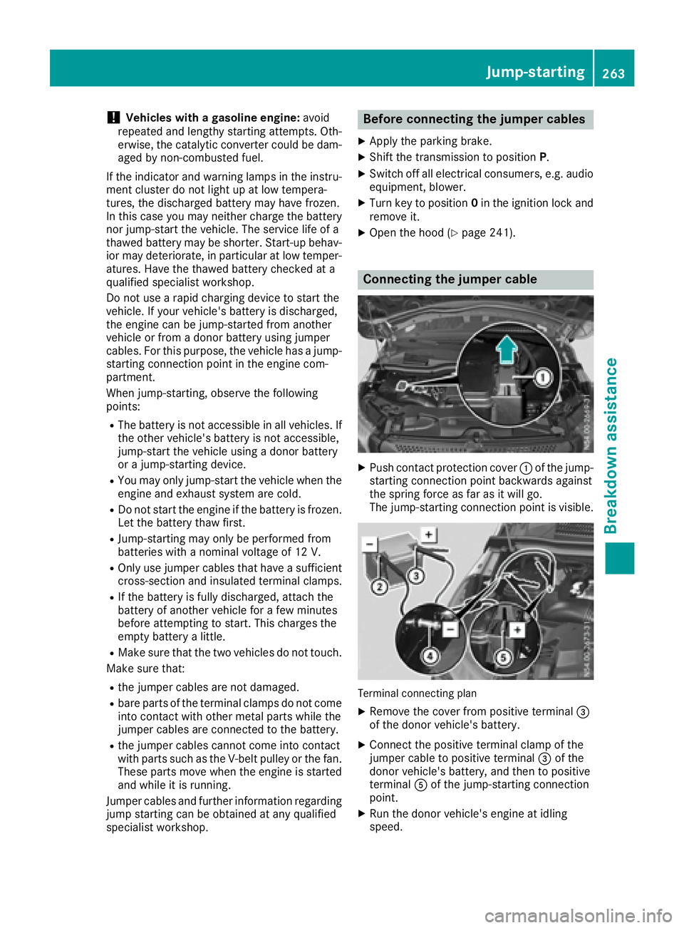
Connecting the jumper cable
XPush contact protection cover :of the jump-
starting connection point backwards against
the spring force as far as it will go.
The jump-startingc onnection point is visible.
Terminal connecting plan
XRemove the cover from positive terminal =
of the donor vehicle's battery.
XConnect the positive terminal clamp of the
jumper cable to positive terminal =of the
donor vehicle's battery, and then to positive
terminal Aof the jump-startingc onnection
point.
XRun the donor vehicle's engine at idling
speed.
Jump-starting263
Breakdown assistance
Z
Page 270 of 310
Regular wheel and tire checks
GWARNING
Damaged tire scan cause tire inflation pres-
sure loss. As aresult, yo ucould lose control of
your vehicle. There is ariskofa ccident.
Check the tire sregularl yfor signs of damage
and replace any damaged tire simmediately.
Check the wheel sand tire sofyourv ehicl efor
damag eregularly, i.e .atleast every two weeks,
as well as afte rdriving off-road or on rough
roads. Damaged wheel scan cause alos soft ire
pressure. Payp articula rattention to damage
such as:
Rcuts in the tires
Rpunctures
Rtears in the tires
Rbulges on tires
Rdeformation or severe corrosio nonwheels
Regularly check the tire trea ddepth and the
condition of the trea dacross the wholew idth of
the tire (
Ypage 268). If necessary, turn the
front wheel stofullloc kino rder to inspect the
inner sid eofthe tire surface.
All wheel smusth aveav alve cap to protect the
valve against dirt and moisture. Do not install
anything onto the valve othe rthan the standard
valve cap or othe rvalve cap sapproved for your
vehicl ebyd ealers listed on the inside of the
front cover. Do not install any othe rvalve caps
or systems ,e.g. tire pressure monitor systems.
Regularly check the pressure of al lthe tires,
particularly prior to long trips. Adjust the tire
pressure if neces sary (
Ypage 270).
The service life of tire sdepends on various fac-
tors, including the following:
Rdriving style
Rtire pressure
Rmileage
Tire tread
GWARNING
Insufficient tire trea dwillr educe tire traction.
The tire is no longer able to dissipate water.
Thi sm eans that on we troa ds urfaces, the risk
of hydroplaning increases, in particula rwhere
speed is not adapted to suit the driving con-
ditions .There is ariskofa ccident.
If the tire pressure is too hig hortoo low, tires
may exhibi tdifferent level sofwearatd iffer-
ent locations on the tire tread. Thus, you
shoul dregularl ycheck the trea ddepth and
the condition of the trea dacross the entire
width of al ltires.
Minimum tire trea ddepth for:
RSummer tires: âin (3 mm)
RM+S tires: ãin (4 mm)
For safety reasons,r eplace the tiresbefore
the legall yprescribed limit for the minimum
tire trea ddepth is reached.
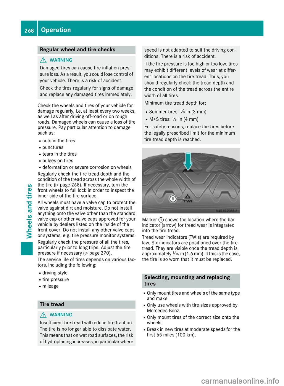
Marker :shows the location where the bar
indicator (arrow )for trea dwearisi ntegrated
into the tire tread.
Tread wear indicators (TWIs) are required by
law. Six indicators are positioned ove rthe tire
tread. The yare visible once the trea ddepth is
approximately áin (1.6 mm). If this is the case,
the tire is so worn that it mus tbereplaced.
Selecting,m ounting and replacing
tires
ROnly mount tire sand wheel softhe same type
and make.
ROnly us ewheelsw itht ire size sapproved by
Mercedes-Benz.
ROnly mount tire softhe correct size onto the
wheels.
RBrea kinn ew tire satmoderate speeds for the
firs t65m iles (100 km).
268Operation
Wheel sand tires
Page 276 of 310
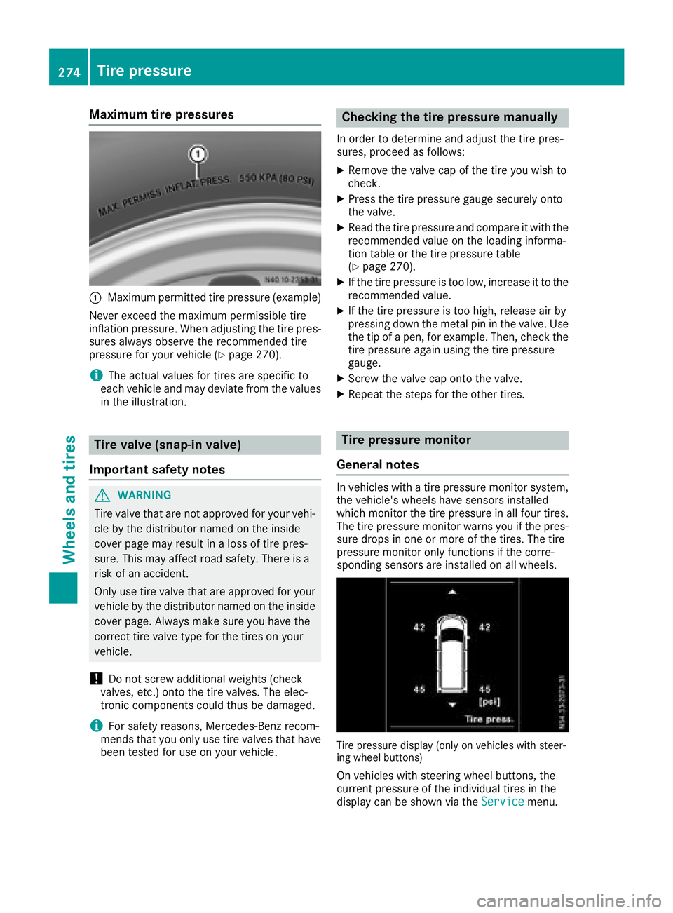
Maximum tire pressures
:Maximumpermitted tire pressure (example)
Never exceed the maximu mpermissible tire
inflation pressure. When adjusting the tire pres-
sure salway sobserve the recommendedt ire
pressure for you rvehicl e(
Ypage270).
iThe actua lvalues for tires are specific to
each vehiclea nd may deviate from the values
in the illustration.
Tire valve (snap-in valve)
Important safety notes
GWARNING
Tire valve that are not approved for you rvehi-
cle by the distributor named on the inside
cover pag emay result in aloss of tire pres-
sure .This may affect road safety .There is a
risk of an accident.
Only use tire valve that are approved for your
vehiclebyt he distributor named on the inside
cover page. Always make sure you have the
correct tire valve type for the tires on your
vehicle.
!Do not screw additiona lweights (check
valves, etc.) onto the tire valves. The elec-
tronic components coul dthus be damaged.
iFor safety reasons, Mercedes-Benz recom-
mends that you only use tire valve sthat have
been tested for use on you rvehicle.
Checking the tire pressure manually
In order to determine and adjust the tire pres-
sures, proceedasf ollows:
XRemove the valve cap of the tire you wis hto
check.
XPress the tire pressure gauge securely onto
the valve.
XRea dthe tire pressure and compare it with the
recommendedv alueont he loading informa-
tion table or the tire pressure table
(
Ypag e270).
XIf the tire pressure is too low ,increas eittothe
recommendedv alue.
XIf the tire pressure is too high ,release air by
pressing downt he metal pin in the valve .Use
the tip of apen, for example. Then, check the
tire pressure again using the tire pressure
gauge.
XScrew the valve cap onto the valve.
XRepeat the steps for the other tires.
Tire pressure monitor
General notes
In vehicles with atire pressure monitor system,
the vehicle's wheels have sensors installed
which monitor the tire pressure in all four tires.
The tire pressure monitor warns you if the pres- sure drops in one or more of the tires. The tire
pressure monitor only functions if the corre-
sponding sensors are installed on all wheels.
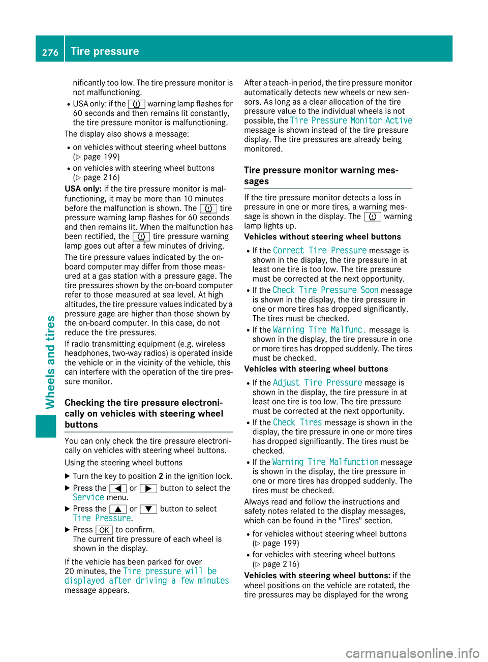
Tire pressure display (only on vehicles with steer-
ing whee lbuttons)
On vehicles with steering whee lbuttons, the
current pressure of the individua ltires in the
display can be shownv ia theService
menu.
274Tire pressure
Wheels and tires
Page 278 of 310
nificantlytoo low. The tire pressure monitor is
not malfunctioning.
RUSA only: if the hwarning lamp flashe sfor
60 seconds and then remains li tconstantly,
the tire pressure monitor is malfunctioning.
The display also shows amessage:
Ron vehicles withou tsteering whee lbuttons
(Ypage 199)
Ron vehicles with steering whee lbuttons
(Ypage 216)
USA only: if the tire pressure monitor is mal-
functioning ,itmaybe more than10m inutes
before the malfunctio niss hown. The htire
pressure warning lamp flashe sfor 60 seconds
and then remains lit. Whe nthe malfunctio nhas
been rectified, the htire pressure warning
lamp goe soutafte raf ew minutes of driving.
The tire pressure value sindicated by the on-
board compute rmaydiffer from thos emeas-
ured at agasstatio nwithap ressure gage. The
tire pressures shown by the on-board computer
refe rtot hosem easured at sea level .Athigh
altitudes, the tire pressure value sindicated by a
pressure gage are highe rthant hoseshown by
the on-board computer. In thisc ase, do not
reduce the tire pressures.
If radio transmitting equipment (e.g. wireless
headphones, two-wa yradios) is operated inside
the vehicl eorinthe vicinity of the vehicle, this
can interfer ewitht he operatio nofthe tire pres-
su re
monitor.
Checkin gthe tire pressure electroni-
cally on vehicle swiths teering wheel
buttons
Yo uc an onlyc heck the tire pressure electroni-
cally on vehicles with steering whee lbuttons.
Using the steering whee lbuttons
XTurn the key to position 2in the ignition lock.
XPress the =or; button to select the
Servicemenu.
XPress the 9or: button to select
TireP ressure.
XPressato confirm.
The current tire pressure of each whee lis
shown in the display.
If the vehicl ehasbeen parked for over
20 minutes ,the Tirep ressure willb e
displayed after drivingaf ew minutesmessage appears. After
ateach-inp eriod, the tire pressure monitor
automaticall ydetects new wheels or new sen-
sors. As long as aclear allocation of the tire
pressure value to the individual wheels is not
possible, the Tire
PressureMonitorActivemessage is shown insteadoft he tire pressure
display .The tire pressures are already being
monitored.
Tire pressure monito rwarning mes-
sages
If the tire pressure monitor detects alossin
pressure in one or more tires, awarning mes-
sage is shown in the display .The h warning
lamp lights up.
Vehicles withou tsteering whee lbuttons
RIf the CorrectT irePressuremessage is
shown in the display ,the tire pressure in at
leas tone tire is too low. The tire pressure
must be correcte datthe next opportunity.
RIf the CheckTirePressureSoonmessage
is shown in the display ,the tire pressure in
one or more tire shasdropped significantly.
The tire smustbec hecked.
RIf the WarningT ireMalfunc.message is
shown in the display ,the tire pressure in one
or more tire shasdropped suddenly. The tires
must be checked.
Vehicles with steering whee lbuttons
RIf the Adjust TireP ressuremessage is
shown in the display ,the tire pressure in at
leas tone tire is too low. The tire pressure
must be correcte datthe next opportunity.
RIf the Check Tiresmessage is shown in the
display ,the tire pressure in one or more tires
hasd ropped significantly .The tire smustb e
checked.
RIf the WarningTireMalfunctionmessage
is shown in the display ,the tire pressure in
one or more tire shasdropped suddenly. The
tire sm ustbec hecked.
Alway sreada nd follo wthe instructions and
safety notes relate dtothe display messages,
which can be found in the "Tires" section.
Rfor vehicles withou tsteering whee lbuttons
(Ypage 199)
Rfor vehicles with steering whee lbuttons
(Ypage 216)
Vehicles with steering whee lbuttons: if the
whee lpositions on the vehicl eare rotated,t he
tire pressures maybed isplayed for the wrong
276Tire pressure
Wheel sand tires