air condition MERCEDES-BENZ ML320 1997 Complete Repair Manual
[x] Cancel search | Manufacturer: MERCEDES-BENZ, Model Year: 1997, Model line: ML320, Model: MERCEDES-BENZ ML320 1997Pages: 4133, PDF Size: 88.89 MB
Page 1616 of 4133

CD PLAYER WITH CHANGER, LOCATION - GF82.64-P-3113-01GI
The CD player with changer is located behind the access flap in the right side cover of the trunk.
Fig. 73: Identifying CD Player With Changer Location
CD PLAYER WITH CHANGER, FUNCTION - GF82.64-P-3113-02GI
Controlling CD player
The CD player with changer (in trunk) (A2/6) is controlled by the radio and navigation module (A2/56)via
the digital data bus (D2B).
The CD player generates reports on the following operating conditions:
No magazine in CD changer
Magazine assignment (only with music CD)
Number of current CD
Number of current title
List of occupied slots (CDs)
Title number per disc
Current operating state (acoustic playback of radio signals, pause, etc.)
The messages are stored on the digital data bus D2B ) and interpreted by the radio and navigation module
(A2/56) .
CD playback
The audio data is stored digitally on the CD-ROM . The audio CD is driven by a motor in the CD-player with
changer (in trunk) (A2/6) .
location/task
Contents - function description
of antenna system (ATS) GF82.62-P-0999GHZ
2001 Mercedes-Benz ML320
1998-2005 ACCESSORIES & BODY, CAB Electrical System - Body - 163 Chassis
me
Saturday, October 02, 2010 3:30:06 PMPage 121 © 2006 Mitchell Repair Information Company, LLC.
Page 1617 of 4133

The laser-optical device scans the non-labeled side of the rotating CDwithout making contact and converts the
digital optical signals into electrical signals. Small interruptions in the data flow of the laser optics caused by
scratches or contamination on the audio CD are compensated by the D/A converter supplementing the missing
values .
The electrical signals are then decoded in the CD player with changer (in trunk) (A2/6) and transmitted via
the digital data bus ( D2B ) to the radio and navigation module (A2/56) via the audio signal processing or
when the sound amplifier (A2/13) (code 810) is installed to the loudspeakers.
Jumps and interruptions during playback
On bad roads or in the event of heavy vibrations , jumps and interruptions can occur during playback. In
such cases do not start CD mode until better road conditions are present.
In the event of wet weather conditions and strong deviations in the ambient temperatures moisture can collect in
the CD player housing (condensation formation). This could also lead to malfunctions in the playback. In such
cases provide for sufficient ventilation of the CD player and the trunk.
CD PLAYER WITH CHANGER, LOCATION/TASK/DESIGN/FUNCTION - GF82.64-P-3113B
MODELS 163, 208, 210, 215, 220 with CODE (819) 6-disc CD changer
MODELS 208, 210, 215, 220 with CODE (819a) CD changer with CODE (498) Japanese version
Shown on model 220 (as of 1.9.02)
Fig. 74: Identifying CD Changer (In Trunk) Location
CD player with changer,
locationThe CD player with
changer (in the trunk)
(A2/6) is located in the
trunk near the left side
wall.
Model 163GF82.64-P-3113-01GI
Models 208, 210GF82.64-P-3113-01D
Models 215, 220 with GF82.64-P-3113-01F
2001 Mercedes-Benz ML320
1998-2005 ACCESSORIES & BODY, CAB Electrical System - Body - 163 Chassis
me
Saturday, October 02, 2010 3:30:06 PMPage 122 © 2006 Mitchell Repair Information Company, LLC.
Page 1665 of 4133

INTERMITTENT INTERRUPTIONS OF RADIO RECEPTION IN RDS MODE - AF82.60-P-1101A
MODELS 163,168,170, 208, 210 with CODE (756a) MB radio Audio 10 RDS with CD compartment
PROBLEM WITH RADIO RECEPTION AFTER INSTALLING SUN SHIELD FILM - AF82.60-P-1105A
MODEL 163, 202, 203, 208, 209, 210, 211, 215, 220
Modification notes
Damage codeCauseRemedy
Under unfavorable
reception conditions in
FM-RDS mode, the radio
may frequently switch to
alternative frequencies of
one and the same radio
station. Due to the equipment
and antenna design there
is no remedy available.
During switchover,
reception may be
interrupted for a brief
period.Do not replace any radios
subject to this complaint
only!
11.2.00Supersedes STIP 82.60-
030 dated 10.2.00
Damage codeCauseRemedy
Complaint is caused by
retrofitting metallized
window foils. When installing
window foils, cut foil
outside of vehicle to
avoid damaging the
antennas and heating
wires
Metallized foil:
AM reception
reduced approx. 70
%, among other
problems search
stop no longer
possible
FM reception
reduced approx. 10
% .
TV reception
reduced approx. 10
Do not use metallized
foil.
Advise customer of
negative effects to
reception
2001 Mercedes-Benz ML320
1998-2005 ACCESSORIES & BODY, CAB Electrical System - Body - 163 Chassis
me
Saturday, October 02, 2010 3:30:07 PMPage 170 © 2006 Mitchell Repair Information Company, LLC.
Page 1680 of 4133

MCS MALFUNCTION - OCCASIONAL FAILURE OF STARGUIDE, SOUND OR CD CHANGER. DTC'S N1111, N1112, N1116
- AF82.95-P-6002A
MODEL 163.157 /174 /175 #A as of 409851 up to 419036 with CODE (349) E Call emergency call system
with CODE (522) Modular control system (MCS) radio USA
Operation no. of operation texts or standard texts and flat rates
other manufacturer.
If the complaint does
not occur during the test
drive, a digitization error
on the navigation CD is
present: ?
4 Inform customers of
facts and manufacturer of
CD with report form
If the correct report
form from the
manufacturer is not
available, please contact
corresponding service
center (telephone number
is given on label of
navigation CD):
5 Check antenna system
for proper function and
repair according to
condition.
If the antenna system
is okay and errors also
occur on other vehicles: ?
6 Inform customer that
the GPS system is
operated by the US
military
RangeOp. no.Operation textTimeAcc. no.Code
P023843FLASH TELEAID
EMERGENCY CALL
SYSTEM CONTROL
MODULE008 WU/0.7 h82 876 90-
Damage codeCauseRemedy
Data transmission of D2B
ring is interrupted. The E-
call control module is in a Recode E-call control
module: ?
2001 Mercedes-Benz ML320
1998-2005 ACCESSORIES & BODY, CAB Electrical System - Body - 163 Chassis
me
Saturday, October 02, 2010 3:30:07 PMPage 185 © 2006 Mitchell Repair Information Company, LLC.
Page 1710 of 4133
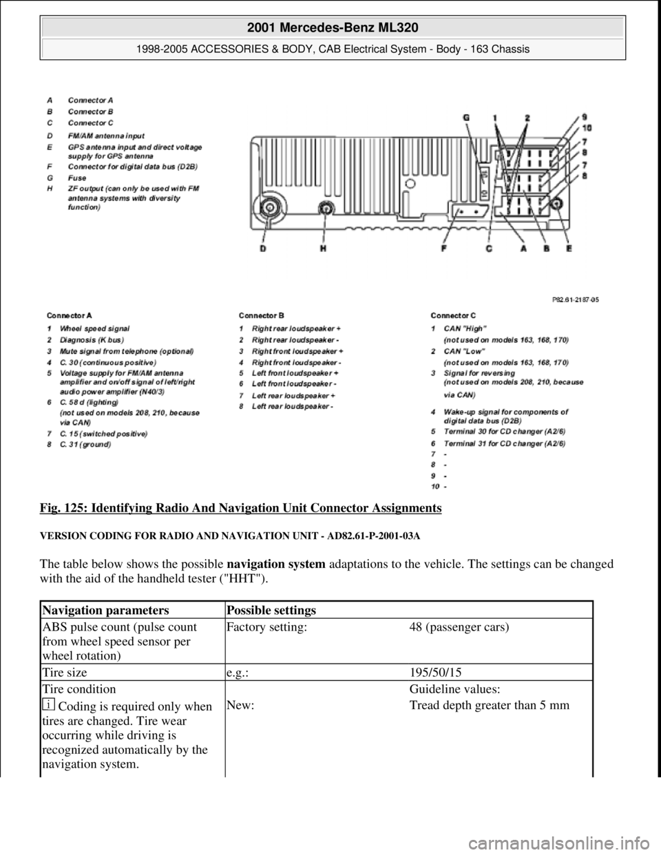
Fig. 125: Identifying Radio And Navigation Unit Connector Assignments
VERSION CODING FOR RADIO AND NAVIGATION UNIT - AD82.61-P-2001-03A
The table below shows the possible navigation system adaptations to the vehicle. The settings can be changed
with the aid of the handheld tester ("HHT").
Navigation parametersPossible settings
ABS pulse count (pulse count
from wheel speed sensor per
wheel rotation)Factory setting:48 (passenger cars)
Tire sizee.g.:195/50/15
Tire condition Guideline values:
Coding is required only when
tires are changed. Tire wear
occurring while driving is
recognized automatically by the
navigation system.New:Tread depth greater than 5 mm
2001 Mercedes-Benz ML320
1998-2005 ACCESSORIES & BODY, CAB Electrical System - Body - 163 Chassis
me
Saturday, October 02, 2010 3:30:08 PMPage 215 © 2006 Mitchell Repair Information Company, LLC.
Page 1764 of 4133

Fig. 169: Identifying License Plate Lamp Components
REMOVING AND INSTALLING CENTER HIGH-MOUNTED STOP LAMP - AR82.10-P-5375GH
MODEL 163
Fig. 170: Identifying Center High
-Mounted Stop Lamp Components
Removal, installation
1Unscrew screws (1)
2Pry out license plate lamp
(E19/3, E19/4) with
suitable tool e.g. plastic wedge
3Reinstall in opposite
order Installation: Check
gasket (2) for license
plate lamp for condition
and proper seating.
4Check for proper function
Removal, installation
1Open tailgate
2Remove cover (1) for
center high-mounted stop
lamp(E21) Press cover in on right
and left (arrow A) until
catch hooks (2) are
2001 Mercedes-Benz ML320
1998-2005 ACCESSORIES & BODY, CAB Electrical System - Body - 163 Chassis
me
Saturday, October 02, 2010 3:30:09 PMPage 269 © 2006 Mitchell Repair Information Company, LLC.
Page 1780 of 4133
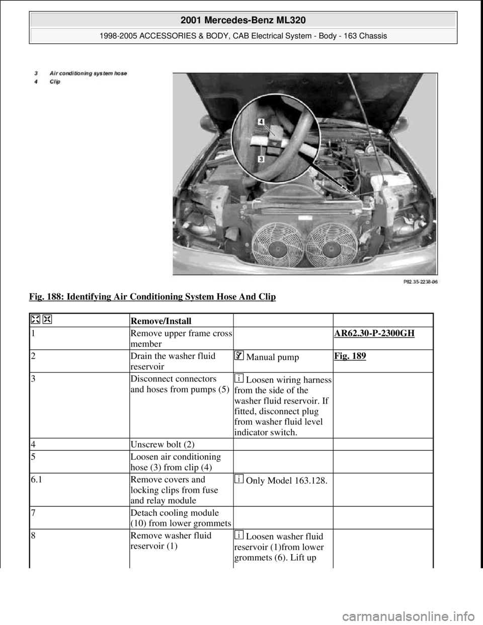
Fig. 188: Identifying Air Conditioning System Hose And Clip
Remove/Install
1Remove upper frame cross
member AR62.30-P-2300GH
2Drain the washer fluid
reservoir Manual pumpFig. 189
3Disconnect connectors
and hoses from pumps (5)Loosen wiring harness
from the side of the
washer fluid reservoir. If
fitted, disconnect plug
from washer fluid level
indicator switch.
4Unscrew bolt (2)
5Loosen air conditioning
hose (3) from clip (4)
6.1Remove covers and
locking clips from fuse
and relay module Only Model 163.128.
7Detach cooling module
(10) from lower grommets
8Remove washer fluid
reservoir (1) Loosen washer fluid
reservoir (1)from lower
grommets (6). Lift up
2001 Mercedes-Benz ML320
1998-2005 ACCESSORIES & BODY, CAB Electrical System - Body - 163 Chassis
me
Saturday, October 02, 2010 3:30:09 PMPage 285 © 2006 Mitchell Repair Information Company, LLC.
Page 1819 of 4133

Fig. 224: Checking Headlamp Adjustment
Check
1Drive vehicle to level
surfaceThe vehicle level must
not change when the
brakes are applied.
Vehicle must be in ready-
for-the-road condition
(unladen weight, fuel tank
full or proper additional
weight).
Correctly adjust tire
pressure.
Load driver's seat with 75
kg or a person (except
USA)
2Align headlamp
adjustment tester to
vehicle and adjust height
according to marking in
lens
Follow the operating
instructions for headlamp
beam setting equipment
exactly*WE58.40-Z-1006-19A
Risk of accident from
vehicle starting off by
itself when engine
running. Risk of injury
suffered in the form of
bruises or burns to the
hands when reaching in
while the engine cranks
or runsSecure vehicle to prevent
it from moving off by
itself.
Wear closed and close-
fitting work clothes.
Do not touch hot or
rotating parts.AS00.00-Z-0005-01A
2001 Mercedes-Benz ML320
1998-2005 ACCESSORIES & BODY, CAB Electrical System - Body - 163 Chassis
me
Saturday, October 02, 2010 3:30:10 PMPage 324 © 2006 Mitchell Repair Information Company, LLC.
Page 1920 of 4133

Fig. 359: Identifying Telephone Console And Assembly Plate
3. Insert mount (1) into assembly plate (10) and install spiral cable into groove (arrow) of telephone console
(12) together with grommet.
Fig. 360: Identifying Mount, Assembly Plate And Telephone Console
4. Screw mount for console (14) to instrument panel with upper right mounting screw (arrow) of air
conditioning control module.
Holder for console (14) must be installed behind A/C control panel.
2001 Mercedes-Benz ML320
1998-2005 ACCESSORIES & BODY, CAB Electrical System - Body - 163 Chassis
me
Saturday, October 02, 2010 3:30:13 PMPage 425 © 2006 Mitchell Repair Information Company, LLC.
Page 1943 of 4133

Parts ordering notes
5Remove air conditioning
pushbutton control
module
6Remove overhead control
panel microphone flap
7Tie antenna lead Tied back in radio
shaft
Install
8Retrofit telephone cable
harness AZ82.70-P-0001-04G
9Retrofit hands-free
system microphone Mount in overhead
control panel.AZ82.70-P-0001-02GH
10Retrofitting telephone
console AZ82.70-P-0001-01G
11Install antenna on roof
See installation
instructions from the
Kathrein company.
12Check portable cellular
telephone for proper
function
13Complete vehicle
(following steps 6 to 1)
Part no.DesignationQuantity
B6 787 57 01Electro kit parts set (for D-net
only)1
B6 788 04 54Portable cellular telephone
console anthracite LHS1
B6 788 04 59Portable cellular telephone
console anthracite RHS1
B6 788 04 55Portable cellular telephone
console orion gray middle LHS1
B6 788 04 58Portable cellular telephone
console orion gray middle RHS1
B6 788 04 56Portable cellular telephone
console java LHS1
B6 788 04 57Portable cellular telephone
console java RHS1
B6 682 86 09Cover (with microphone), color
java
1
B6 682 86 10Cover (with microphone), color
light gray1
2001 Mercedes-Benz ML320
1998-2005 ACCESSORIES & BODY, CAB Electrical System - Body - 163 Chassis
me
Saturday, October 02, 2010 3:30:14 PMPage 448 © 2006 Mitchell Repair Information Company, LLC.