air condition MERCEDES-BENZ ML320 1997 Complete Manual PDF
[x] Cancel search | Manufacturer: MERCEDES-BENZ, Model Year: 1997, Model line: ML320, Model: MERCEDES-BENZ ML320 1997Pages: 4133, PDF Size: 88.89 MB
Page 1121 of 4133
317 Index
A
ABS 25, 76, 311
ABS control 76
LOW RANGE mode 77
Malfunction indicator lamp 242
Warning lamp 242
Accelerator position, automatic
transmission 123
Accident
In case of 52
Activating
Air circulation mode 139
Air recirculation mode 139
Anti-theft alarm system 83
Automatic climate control 135
ESP 82
Exterior headlamps 48
Hazard warning flasher 112
Headlamps 48
High beams 110
Ignition 33Immobilizer 54, 83
Rear passenger compartment ventila-
tion and climate control 141
Rear window defroster 133
Rear window wiper 51
Residual heat 140
Seat heater* 98
Tow-away alarm 85
Warning indicators (Parktronic*) 155
Windshield wipers 50
Activating automatic central locking 93
Adding
Coolant 223
Engine oil 221
Additional turn signals 266
Adjustable steering column
Indicator lamp 253
Adjusting 34
Backrest tilt 36, 38
Exterior rear view mirror 40
Head restraint height 36, 38Head restraint tilt 37, 39
Headlamp aim 272
Instrument cluster illumination 116
Manual seat 35
Mirrors 40
Power seats* 37
Seat cushion tilt 38
Seat fore and aft 35
Seat fore and aft adjustment 37
Seat height 36, 38
Seats 34
Steering wheel 39
Adjusting air distribution
Automatic climate control 137
Adjusting air volume
Automatic climate control 137
Air conditioner (cooling)
Turning on 139
Air conditioning
Cooling 139
Page 1122 of 4133

318 IndexAir conditioning refrigerant 302
Air outlets
Automatic climate control 142
Air pressure see Tire inflation
pressure 227
Air recirculation mode 138
Activating 139
Deactivating 139
AIRBAG OFF
Warning lamp 243
Airbags 59
BabySmart
TM airbag deactivation
system 311
BabySmartTM deactivation
system 70
Children 60
Front 63
Passenger 63
Safety guidelines 62
Side impact 64
Window curtain 64Alarm
Audible 75, 84, 86
Canceling 84, 86
Visual 83
Alarm system
Anti-theft 83
Anticorrosion/antifreeze 305
Antiglare
Automatic 126
Antilock brake system (ABS) 311
Anti-theft alarm system
Arming 83
Canceling alarm 84, 86
Disarming 84
Anti-theft systems
Anti-theft alarm system 83
Immobilizer 83
Tow-away alarm, glass breakage
sensor 84
Aquaplaning see Hydroplaning 197
Armrest
Storage compartment in front of 165
Storage spaces 165Armrest in rear seat bench 167
Ashtray
Front center console 168
Rear center console 169
ATF (automatic transmission fluid) 222
Attaching a trailer 208
Automatic antiglare for rear view
mirror 126
Automatic central locking
Activating 93
Deactivating 93
Automatic climate control 134
Adjusting air distribution 137
Adjusting air volume 137
Air conditioning 139
Air outlets 142
Air recirculation mode 138
Basic setting 137
Changing basic setting 137
Defrosting 138
Economy mode 135
Page 1126 of 4133

322 IndexCoolant 222, 304
Adding 223
Anticorrosion/antifreeze
quantity 304
Checking level 222
Indicator lamp 249
Temperature 213
Temperature gauge 117
Coolant level
Checking 215, 222
Crossing obstacles 204
Cruise control 150, 311
Canceling 151
Driving downhill 151
Driving uphill 151
Fine adjustment 152
LOW RANGE mode 152
Saving current speed 151
Setting speeds 152
Cruise control lever 150Cup holder 166
Cleaning 238
In front seat armrest 167
In instrument panel 166
In rear centerconsole 167
Customer Assistance Center (CAC) 311
D
Daytime running lamp mode 109
Deactivating
Air conditioning (cooling) 139
Air recirculation mode 139
Alarm 84
Anti-theft alarm system 84
Automatic climate control 135, 137
Cruise control 151
Defrost 138
Engine 54
ESP 81
Front fog lamps, rear fog lamp 111
Hazard warning flasher 112
Headlamps 54
Immobilizer 83
Rear passenger compartment ventila-
tion and climate control 141
Rear window defroster 133Residual heat 140
Seat heater* 98
Tow-away alarm 85
Tow-away alarm (vehicles with trip
computer*) 85
Tow-away alarm (vehicles without trip
computer*) 86
Deactivating automatic central
locking 93
Deep water see Standing water 200
Defogging
Windshield 138
Defrosting 138
Difficulties
While driving see Problems while
driving 51
With starting 47
Direction of rotation (tires) 227
Discharged battery
Jump starting 281
Disconnecting
Vehicle battery 279
Display in the speedometer 117
Page 1137 of 4133

333 Index
Reading lamps 114
Rear automatic climate control 141
Adjusting air volume and air distribu-
tion manually 141
Automatic mode 141
Rear bench seat
Foldable 99
Rear door window
Blocking operation 73
Rear fog lamp 267
Bulb 267
Switching on 111
Rear lamp bulbs
Replacing 270
Rear parking lamp
Replacing bulbs 270
Rear passenger compartment ventilation
and climate control
Activating 141
Deactivating 141
Rear passenger compartment ventilation
and rear automatic climate
control 141Rear quarter windows* 146
Opening 146
Closing 147
Rear seats 99
Easy entry/exit feature* 101
Enlarging cargo area 99
Folding down backrest 100
Folding up 101
Folding up backrest 100
Fore and aft 99
Lowering 100
Third row* 102
Rear standing lamp
Replacing bulbs 270
Rear towing eyes 285
Rear view mirror automatic antiglare 126
Rear view mirrors see Mirrors
Rear window defroster 133
Activating 133
Deactivating 133Rear window wiper 131
Rain sensor* 131
Rear window wiper/washer 51
Reconnecting
Vehicle battery 279
Refrigerant
Air conditioning 302
Refueling 214
Regular checks 215
Reinstalling vehicle battery 279
Remote control
Changing battery 262
Global locking 89
Global unlocking 89
Synchronizing 263
Unlocking liftgate 89
Unlocking the driver’s door, fuel filler
flap 89
Unlocking with 32
Remote control with folding key 88
Page 1172 of 4133
Remove/Install
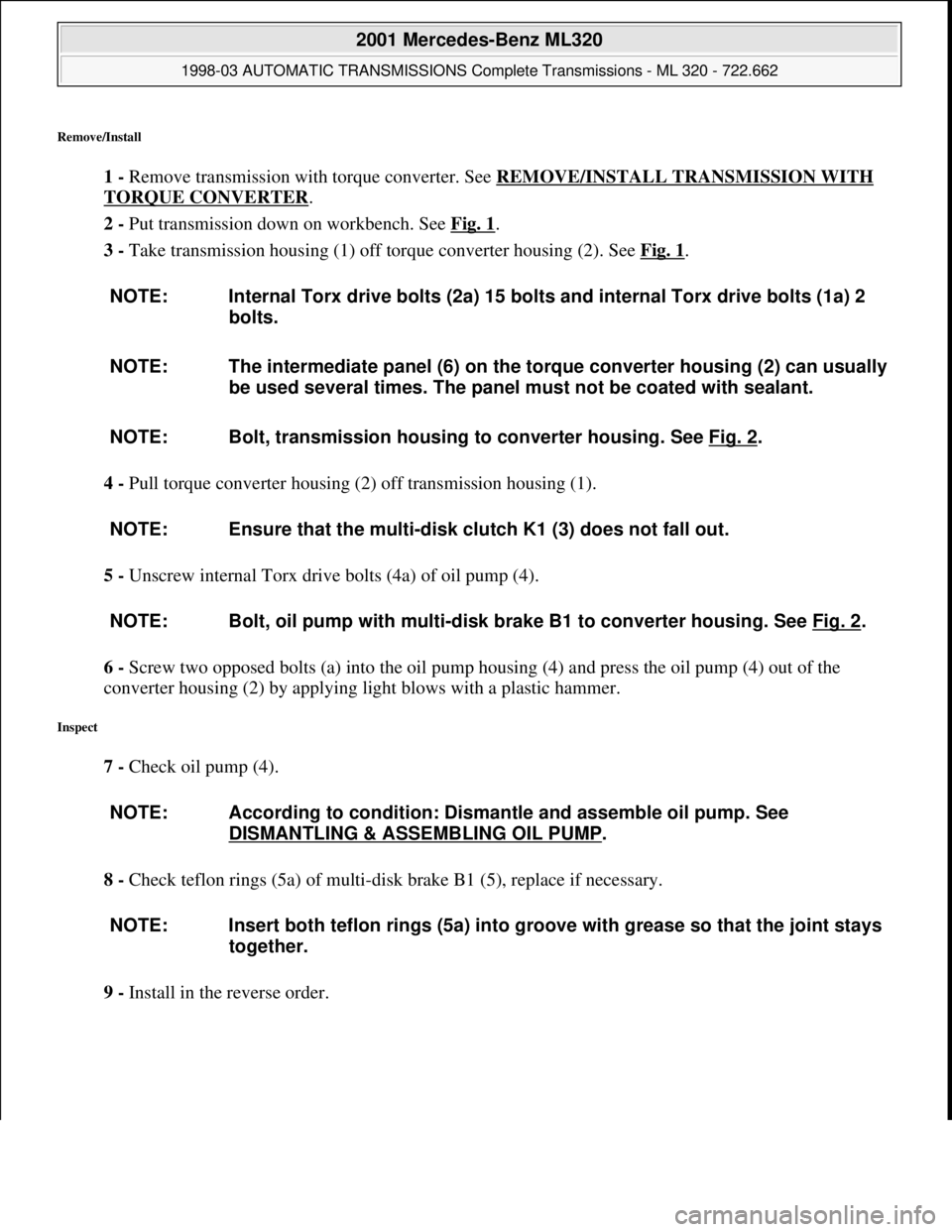
1 - Remove transmission with torque converter. See REMOVE/INSTALL TRANSMISSION WITH
TORQUE CONVERTER.
2 - Put transmission down on workbench. See Fig. 1
.
3 - Take transmission housing (1) off torque converter housing (2). See Fig. 1
.
4 - Pull torque converter housing (2) off transmission housing (1).
5 - Unscrew internal Torx drive bolts (4a) of oil pump (4).
6 - Screw two opposed bolts (a) into the oil pump housing (4) and press the oil pump (4) out of the
converter housing (2) by applying light blows with a plastic hammer.
Inspect
7 - Check oil pump (4).
8 - Check teflon rings (5a) of multi-disk brake B1 (5), replace if necessary.
9 - Install in the reverse order. NOTE: Internal Torx drive bolts (2a) 15 bolts and internal Torx drive bolts (1a) 2
bolts.
NOTE: The intermediate panel (6) on the torque converter housing (2) can usually
be used several times. The panel must not be coated with sealant.
NOTE: Bolt, transmission housing to converter housing. See Fig. 2
.
NOTE: Ensure that the multi-disk clutch K1 (3) does not fall out.
NOTE: Bolt, oil pump with multi-disk brake B1 to converter housing. See Fig. 2
.
NOTE: According to condition: Dismantle and assemble oil pump. See
DISMANTLING & ASSEMBLING OIL PUMP
.
NOTE: Insert both teflon rings (5a) into groove with grease so that the joint stays
together.
2001 Mercedes-Benz ML320
1998-03 AUTOMATIC TRANSMISSIONS Complete Transmissions - ML 320 - 722.662
me
Saturday, October 02, 2010 3:15:25 PMPage 3 © 2006 Mitchell Repair Information Company, LLC.
Page 1286 of 4133

Fig. 64: Modulating Pressure Regulating Solenoid Valve, Location/Task/Design/Function
Courtesy of MERCEDES-BENZ OF NORTH AMERICA.
Modulating Pressure Regulating Solenoid Valve, Location
In the supporting body of the electrical control unit (Y3/6) and pressed against the valve housing of the
shift plate (2a) by means of a leaf spring. See Fig. 64
.
Modulating Pressure Regulating Solenoid Valve, Task
To control the modulating pressure depending on the constantly changing operating conditions such as
load/gear changes.
Modulating Pressure Regulating Solenoid Valve, Design
See MODULATING PRESSURE REGULATING SOLENOID VALVE, DESIGN
.
Modulating Pressure Regulating Solenoid Valve, Function
The modulating pressure regulating solenoid valve (Y3/6y1) assigns a proportional pressure to the current
which is controlled by the ETC control module (N15/3) according to the load.
Modulating Pressure Regulating Solenoid Valve, Design
2001 Mercedes-Benz ML320
1998-03 AUTOMATIC TRANSMISSIONS Complete Transmissions - ML 320 - 722.662
me
Saturday, October 02, 2010 3:15:27 PMPage 117 © 2006 Mitchell Repair Information Company, LLC.
Page 1290 of 4133

Fig. 66: Shift Pressure Regulating Solenoid Valve, Location/Task/Design/Function
Courtesy of MERCEDES-BENZ OF NORTH AMERICA.
Shift Pressure Regulating Solenoid Valve, Location
In the supporting body of the electrical control unit (Y3/6) and pressed against the valve housing of the
shift plate (2a) by means of a leaf spring. See Fig. 66
.
Shift Pressure Regulating Solenoid Valve, Task
To control the shift pressure depending on the constantly changing operating conditions, such as
load/gear changes.
Shift Pressure Regulating Solenoid Valve, Design
See SHIFT PRESSURE REGULATING SOLENOID VALVE, DESIGN
.
Shift Pressure Regulating Solenoid Valve, Function
The shift pressure regulating solenoid valve (Y3/6y2) assigns a proportional pressure to the current which
is controlled by the ETC control module (N15/3) according to the load.
Shift Pressure Regulating Valve, Location/Task/Function
2001 Mercedes-Benz ML320
1998-03 AUTOMATIC TRANSMISSIONS Complete Transmissions - ML 320 - 722.662
me
Saturday, October 02, 2010 3:15:27 PMPage 121 © 2006 Mitchell Repair Information Company, LLC.
Page 1316 of 4133

Fig. 83: R/P-Lock, Function (Locking Position)
Courtesy of MERCEDES-BENZ OF NORTH AMERICA.
Function Of R/P Lock - The selector lever position "P" is locked whenever the R/P locking solenoid (89) is not
actuated by the electronic selector lever module control module (N15/5). See Fig. 83
. The prerequisites for this
are as follows:
No voltage supply to the electronic selector lever module control module (N15/5).
Brake pedal not depressed.
Under these conditions the locking lever (90) is in the locking position (P-lock).
The web on the locking lever (P-lock) (90b) locks the locking disc (69). It is not possible to shift the selector
lever (80) out of selector lever position "P".
Shift Detent Mechanism, Location/Task/Design/Function (Without Touch Shift)
2001 Mercedes-Benz ML320
1998-03 AUTOMATIC TRANSMISSIONS Complete Transmissions - ML 320 - 722.662
me
Saturday, October 02, 2010 3:15:27 PMPage 147 © 2006 Mitchell Repair Information Company, LLC.
Page 1325 of 4133

Shift Pressure Shift Valve, Function
See SHIFT PRESSURE SHIFT VALVE, FUNCTION
.
Shift Pressure Shift Valve, Function
Fig. 91: Shift Pressure Shift Valve, Function
Courtesy of MERCEDES-BENZ OF NORTH AMERICA.
Operation - When the multiple-disc brake (B) is engaged, the working pressure (p-A) is applied to the end face
of the shift valve (29) via the command valve (31). See Fig. 91
. Its shift condition is retained in the shift phase,
2001 Mercedes-Benz ML320
1998-03 AUTOMATIC TRANSMISSIONS Complete Transmissions - ML 320 - 722.662
me
Saturday, October 02, 2010 3:15:27 PMPage 156 © 2006 Mitchell Repair Information Company, LLC.
Page 1326 of 4133

whilst the shift element pressure acting on the end face and which is variable during the shift phase is replaced
by a corresponding, constant pressure.
When the multiple-disc clutch (K) is engaged (K) the end face of the shift pressure shift valve (29) is
depressurized during the stationary and shift phases, here the shift condition is also retained during the shift
phase.
Shift Pressure Regulating Valve, Location/Task/Function Also Float, Location/Function
2001 Mercedes-Benz ML320
1998-03 AUTOMATIC TRANSMISSIONS Complete Transmissions - ML 320 - 722.662
me
Saturday, October 02, 2010 3:15:27 PMPage 157 © 2006 Mitchell Repair Information Company, LLC.