cooling MERCEDES-BENZ ML320 1997 Complete Repair Manual
[x] Cancel search | Manufacturer: MERCEDES-BENZ, Model Year: 1997, Model line: ML320, Model: MERCEDES-BENZ ML320 1997Pages: 4133, PDF Size: 88.89 MB
Page 3381 of 4133

Shown on model 203
Fig. 117: Identifying Pressure Relief Valve And Refrigerant Compressor
- Shown On Model 203
TEMPERATURE CONTROL, FUNCTION - GF83.57-P-2000GH
MODEL 163 up to 31.08.01 with CODE (580) Air conditioning or Tempmatic for USA
Function
The temperature preselected at the temperature selector wheels is reached or kept constant by:
heating up by the heat exchanger,
heating up by the electric heater booster (with engine 612.963 only)
cooling by the evaporator core,
cooling and reheating (reheat mode).
Heating up
The heating system heat exchanger heats the air passing by, which is then conducted into the vehicle interior by
the air ducts.
Heating up by the electric heater booster
Due to the high level of efficiency of the direct-injection diesel engine, the heat output of the coolant is not
sufficient to heat the fresh air. By installing the electric heater booster, behind the heating system heat
exchanger, this heating capacity deficit is compensated.
Pressure relief
valve, positionThe pressure relief valve (3) is located on the refrigerant
compressor (A9).
Pressure relief
valve, taskThe pressure relief valve (3) serves to protect the refrigerant
circuit from damage caused by excess pressure.
Pressure relief
valve, function GF83.55-P-
2104-02P
2001 Mercedes-Benz ML320
1998-2005 HVAC Climate Control - 163 Chassis
me
Saturday, October 02, 2010 3:23:17 PMPage 137 © 2006 Mitchell Repair Information Company, LLC.
Page 3382 of 4133
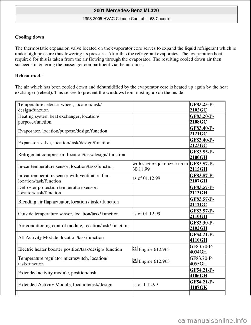
Cooling down
The thermostatic expansion valve located on the evaporator core serves to expand the liquid refrigerant which is
under high pressure thus lowering its pressure. After this the refrigerant evaporates. The evaporation heat
required for this is taken from the air flowing through the evaporator. The resulting cooled down air then
succeeds in entering the passenger compartment via the air ducts.
Reheat mode
The air which has been cooled down and dehumidified by the evaporator core is heated up again by the heat
exchanger (reheat). This serves to prevent the windows from misting up on the inside.
Temperature selector wheel, location/task/
design/function GF83.25-P-
2102GC
Heating system heat exchanger, location/
purpose/function GF83.20-P-
2108GC
Evaporator, location/purpose/design/function GF83.40-P-
2121GC
Expansion valve, location/task/design/function GF83.40-P-
2123GC
Refrigerant compressor, location/task/design/ function GF83.55-P-
2100GH
In-car temperature sensor, location/task/functionwith suction jet nozzle up to
30.11.99GF83.57-P-
2115GH
In-car temperature sensor with ventilation fan,
location/task/functionas of 01.12.99GF83.57-P-
2107GH
Defroster protection temperature sensor,
location/task/function GF83.57-P-
2113GH
Blending air flap actuator, location / task / function GF83.57-P-
2112GC
Outside temperature sensor, location/task/ functionas of 01.12.99GF83.57-P-
2110GH
Air conditioning control module, location/task/ function GF83.30-P-
2102GH
All Activity Module, location/task/function GF54.21-P-
4110GH
Electric heater booster position/task/design/ function Engine 612.963GF83.70-P-
4054GH
Temperature regulator microswitch, location/
task/function Engine 612.963GF83.70-P-
4055GH
Extended activity module, position/task GF54.21-P-
4106GH
Extended Activity Module, location/task/designas of 1.12.99GF54.21-P-
4107GK
2001 Mercedes-Benz ML320
1998-2005 HVAC Climate Control - 163 Chassis
me
Saturday, October 02, 2010 3:23:17 PMPage 138 © 2006 Mitchell Repair Information Company, LLC.
Page 3383 of 4133
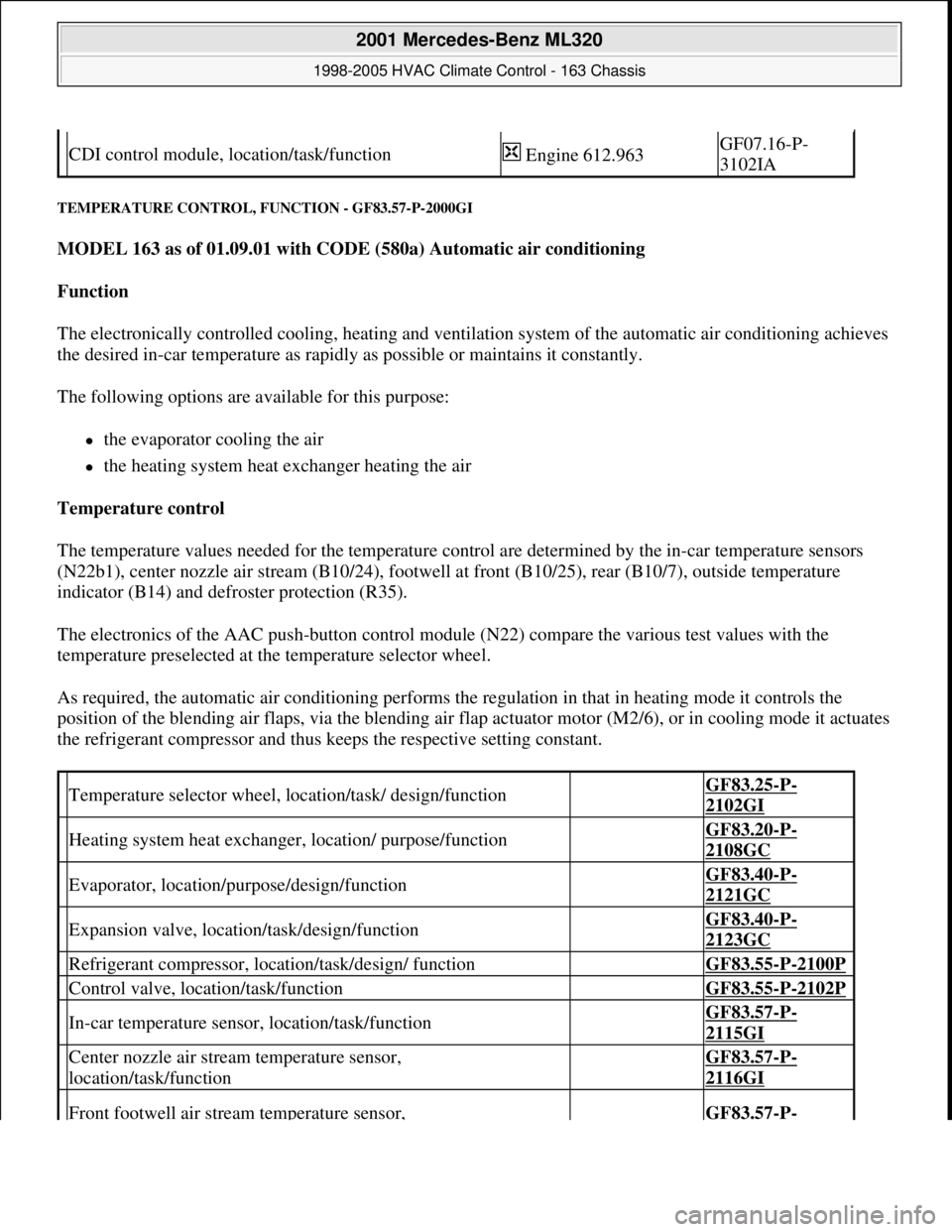
TEMPERATURE CONTROL, FUNCTION - GF83.57-P-2000GI
MODEL 163 as of 01.09.01 with CODE (580a) Automatic air conditioning
Function
The electronically controlled cooling, heating and ventilation system of the automatic air conditioning achieves
the desired in-car temperature as rapidly as possible or maintains it constantly.
The following options are available for this purpose:
the evaporator cooling the air
the heating system heat exchanger heating the air
Temperature control
The temperature values needed for the temperature control are determined by the in-car temperature sensors
(N22b1), center nozzle air stream (B10/24), footwell at front (B10/25), rear (B10/7), outside temperature
indicator (B14) and defroster protection (R35).
The electronics of the AAC push-button control module (N22) compare the various test values with the
temperature preselected at the temperature selector wheel.
As required, the automatic air conditioning performs the regulation in that in heating mode it controls the
position of the blending air flaps, via the blending air flap actuator motor (M2/6), or in cooling mode it actuates
the refrigerant compressor and thus keeps the respective setting constant.
CDI control module, location/task/function Engine 612.963GF07.16-P-
3102IA
Temperature selector wheel, location/task/ design/function GF83.25-P-
2102GI
Heating system heat exchanger, location/ purpose/function GF83.20-P-
2108GC
Evaporator, location/purpose/design/function GF83.40-P-
2121GC
Expansion valve, location/task/design/function GF83.40-P-
2123GC
Refrigerant compressor, location/task/design/ function GF83.55-P-2100P
Control valve, location/task/function GF83.55-P-2102P
In-car temperature sensor, location/task/function GF83.57-P-
2115GI
Center nozzle air stream temperature sensor,
location/task/function GF83.57-P-
2116GI
Front footwell air stream temperature sensor, GF83.57-P-
2001 Mercedes-Benz ML320
1998-2005 HVAC Climate Control - 163 Chassis
me
Saturday, October 02, 2010 3:23:17 PMPage 139 © 2006 Mitchell Repair Information Company, LLC.
Page 3398 of 4133
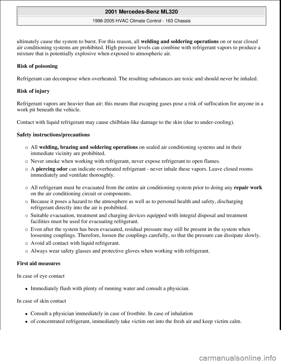
ultimately cause the system to burst. For this reason, all welding and soldering operations on or near closed
air conditioning systems are prohibited. High pressure levels can combine with refrigerant vapors to produce a
mixture that is potentially explosive when exposed to atmospheric air.
Risk of poisoning
Refrigerant can decompose when overheated. The resulting substances are toxic and should never be inhaled.
Risk of injury
Refrigerant vapors are heavier than air; this means that escaping gases pose a risk of suffocation for anyone in a
work pit beneath the vehicle.
Contact with liquid refrigerant may cause chilblain-like damage to the skin (due to under-cooling).
Safety instructions/precautions
All welding, brazing and soldering operations on sealed air conditioning systems and in their
immediate vicinity are prohibited.
Never smoke when working with refrigerant, never expose refrigerant to open flames.
A piercing odor can indicate overheated refrigerant - never inhale these vapors. Leave closed rooms
immediately and ventilate thoroughly.
All refrigerant must be evacuated from the entire air conditioning system prior to doing any repair work
on the air conditioning circuit or components.
Because it poses a hazard to the atmosphere as well as to personal health and safety, discharging
refrigerant directly into the air is prohibited.
Suitable evacuation, treatment and charging devices equipped with integral disposal and treatment
facilities must be used for evacuating refrigerant.
Even after the system has been evacuated, residual pressure may still be present in the system when
loosening couplings. Therefore, loosen the couplings carefully, so that the pressure can dissipate slowly.
Avoid all contact with liquid refrigerant.
Always wear safety glasses and protective gloves when working with refrigerant.
First aid measures
In case of eye contact
Immediately flush with plenty of running water and consult a physician.
In case of skin contact
Consult a physician immediately in case of frostbite. In case of inhalation
of concentrated refrigerant, immediately take victim out into the fresh air and keep victim calm.
2001 Mercedes-Benz ML320
1998-2005 HVAC Climate Control - 163 Chassis
me
Saturday, October 02, 2010 3:23:17 PMPage 154 © 2006 Mitchell Repair Information Company, LLC.
Page 3402 of 4133
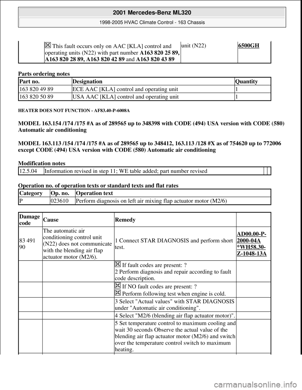
Parts ordering notes
HEATER DOES NOT FUNCTION - AF83.40-P-6008A
MODEL 163.154 /174 /175 #A as of 289565 up to 348398 with CODE (494) USA version with CODE (580)
Automatic air conditioning
MODEL 163.113 /154 /174 /175 #A as of 289565 up to 348412, 163.113 /128 #X as of 754620 up to 772006
except CODE (494) USA version with CODE (580) Automatic air conditioning
Modification notes
Operation no. of operation texts or standard texts and flat rates
This fault occurs only on AAC [KLA] control and
operating units (N22) with part number A163 820 25 89,
A163 820 28 89, A163 820 42 89 and A163 820 43 89 unit (N22)6500GH
Part no.DesignationQuantity
163 820 49 89ECE AAC [KLA] control and operating unit1
163 820 50 89USA AAC [KLA] control and operating unit1
12.5.04Information revised in step 11; WE table added; part number revised
CategoryOp. no.Operation text
P023610Perform diagnosis on left air mixing flap actuator motor (M2/6)
Damage
codeCauseRemedy
83 491
90
The automatic air
conditioning control unit
(N22) does not communicate
with the blending air flap
actuator motor (M2/6).
1 Connect STAR DIAGNOSIS and perform short
test.
AD00.00-P-
2000-04A
*WH58.30
-
Z-1048-13A
If fault codes are present: ?
2 Perform diagnosis and repair according to fault
code description.
If NO fault codes are present: ?
Perform following test when engine is cold.
3 Select "Actual values" with STAR DIAGNOSIS
under "Automatic air conditioning".
4 Select "M2/6 (blending air flap actuator motor)".
5 Set temperature control to maximum cooling and
wait 30 seconds Observe the actual value of the
blending air flap actuator motor (M2/6) and switch
over the temperature control switch to maximum
heating.
2001 Mercedes-Benz ML320
1998-2005 HVAC Climate Control - 163 Chassis
me
Saturday, October 02, 2010 3:23:17 PMPage 158 © 2006 Mitchell Repair Information Company, LLC.
Page 3404 of 4133
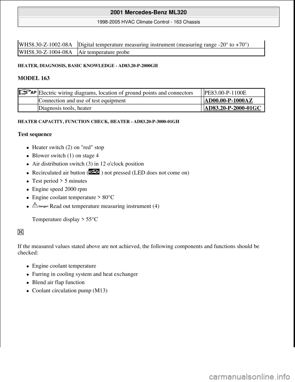
HEATER, DIAGNOSIS, BASIC KNOWLEDGE - AD83.20-P-2000GH
MODEL 163
HEATER CAPACITY, FUNCTION CHECK, HEATER - AD83.20-P-3000-01GH
Test sequence
Heater switch (2) on "red" stop
Blower switch (1) on stage 4
Air distribution switch (3) in 12 o'clock position
Recirculated air button ( ) not pressed (LED does not come on)
Test period > 5 minutes
Engine speed 2000 rpm
Engine coolant temperature > 80°C
Read out temperature measuring instrument (4)
Temperature display > 55°C
If the measured values stated above are not achieved, the following components and functions should be
checked:
Engine coolant temperature
Furring in cooling system and heat exchanger
Blend air flap function
Coolant circulation pump (M13)
WH58.30-Z-1002-08ADigital temperature measuring instrument (measuring range -20° to +70°)
WH58.30-Z-1004-08AAir temperature probe
Electric wiring diagrams, location of ground points and connectors PE83.00-P-1100E
Connection and use of test equipment AD00.00-P-1000AZ
Diagnosis tools, heater AD83.20-P-2000-01GC
2001 Mercedes-Benz ML320
1998-2005 HVAC Climate Control - 163 Chassis
me
Saturday, October 02, 2010 3:23:17 PMPage 160 © 2006 Mitchell Repair Information Company, LLC.
Page 3406 of 4133
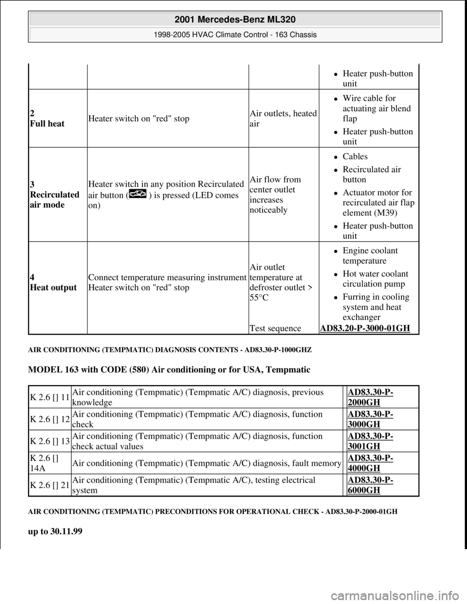
AIR CONDITIONING (TEMPMATIC) DIAGNOSIS CONTENTS - AD83.30-P-1000GHZ
MODEL 163 with CODE (580) Air conditioning or for USA, Tempmatic
AIR CONDITIONING (TEMPMATIC) PRECONDITIONS FOR OPERATIONAL CHECK - AD83.30-P-2000-01GH
up to 30.11.99
Heater push-button
unit
2
Full heat Heater switch on "red" stopAir outlets, heated
air
Wire cable for
actuating air blend
flap
Heater push-button
unit
3
Recirculated
air mode Heater switch in any position Recirculated
air button ( ) is pressed (LED comes
on)Air flow from
center outlet
increases
noticeably
Cables
Recirculated air
button
Actuator motor for
recirculated air flap
element (M39)
Heater push-button
unit
4
Heat output Connect temperature measuring instrument
Heater switch on "red" stop
Air outlet
temperature at
defroster outlet >
55°C
Engine coolant
temperature
Hot water coolant
circulation pump
Furring in cooling
system and heat
exchanger
Test sequenceAD83.20-P-3000-01GH
K 2.6 [] 11Air conditioning (Tempmatic) (Tempmatic A/C) diagnosis, previous
knowledge AD83.30-P-
2000GH
K 2.6 [] 12Air conditioning (Tempmatic) (Tempmatic A/C) diagnosis, function
check AD83.30-P-
3000GH
K 2.6 [] 13Air conditioning (Tempmatic) (Tempmatic A/C) diagnosis, function
check actual values AD83.30-P-
3001GH
K 2.6 []
14AAir conditioning (Tempmatic) (Tempmatic A/C) diagnosis, fault memory AD83.30-P-
4000GH
K 2.6 [] 21Air conditioning (Tempmatic) (Tempmatic A/C), testing electrical
system AD83.30-P-
6000GH
2001 Mercedes-Benz ML320
1998-2005 HVAC Climate Control - 163 Chassis
me
Saturday, October 02, 2010 3:23:17 PMPage 162 © 2006 Mitchell Repair Information Company, LLC.
Page 3425 of 4133
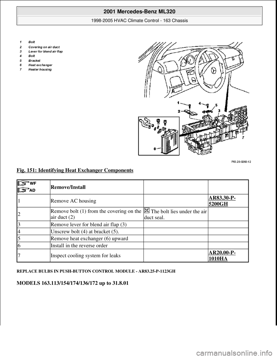
Fig. 151: Identifying Heat Exchanger Components
REPLACE BULBS IN PUSH-BUTTON CONTROL MODULE - AR83.25-P-1123GH
MODELS 163.113/154/174/136/172 up to 31.8.01
Remove/Install
1Remove AC housing AR83.30-P-
5200GH
2Remove bolt (1) from the covering on the
air duct (2)The bolt lies under the air
duct seal.
3Remove lever for blend air flap (3)
4Unscrew bolt (4) at bracket (5).
5Remove heat exchanger (6) upward
6Install in the reverse order
7Inspect cooling system for leaks AR20.00-P-
1010HA
2001 Mercedes-Benz ML320
1998-2005 HVAC Climate Control - 163 Chassis
me
Saturday, October 02, 2010 3:23:18 PMPage 181 © 2006 Mitchell Repair Information Company, LLC.
Page 3440 of 4133
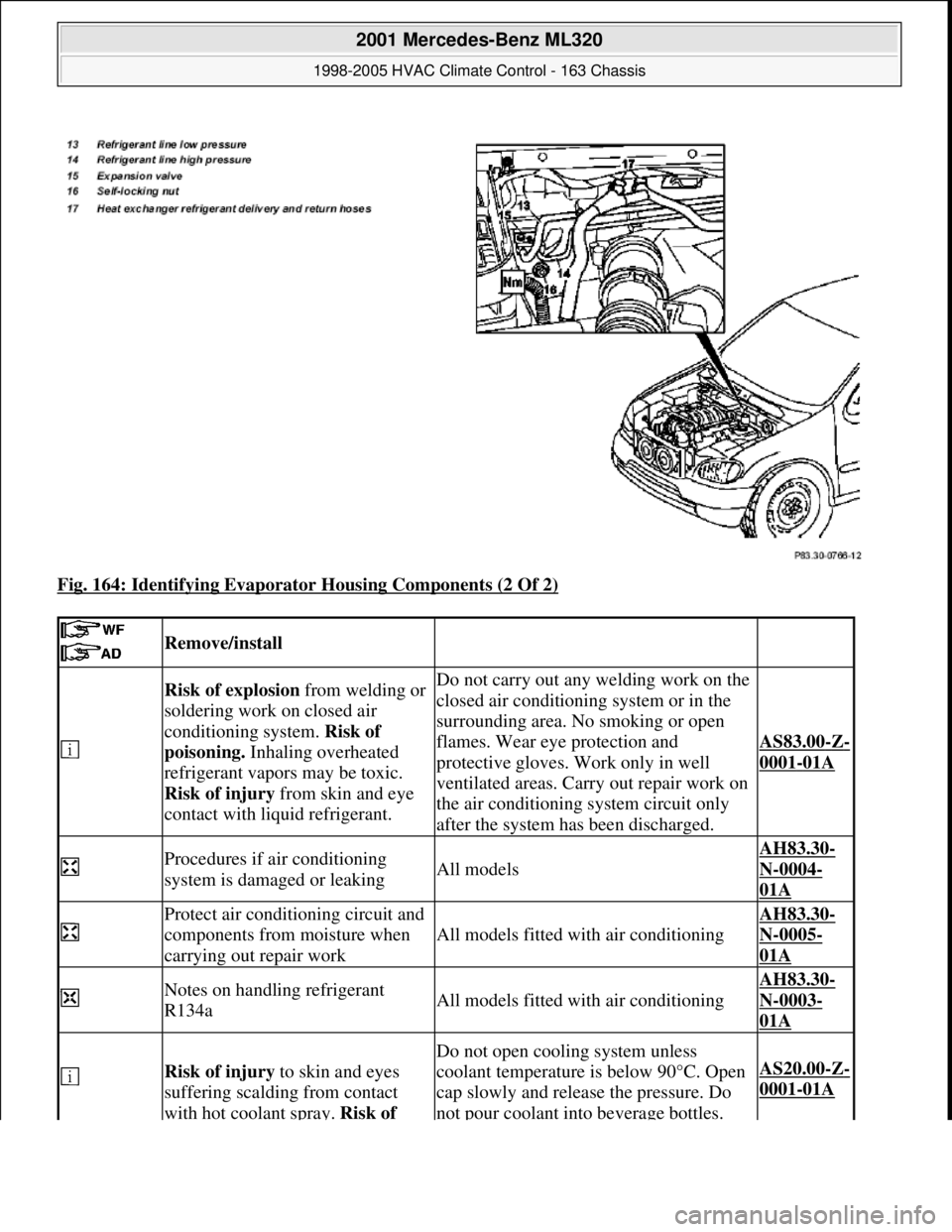
Fig. 164: Identifying Evaporator Housing Components (2 Of 2)
Remove/install
Risk of explosion from welding or
soldering work on closed air
conditioning system. Risk of
poisoning. Inhaling overheated
refrigerant vapors may be toxic.
Risk of injury from skin and eye
contact with liquid refrigerant.Do not carry out any welding work on the
closed air conditioning system or in the
surrounding area. No smoking or open
flames. Wear eye protection and
protective gloves. Work only in well
ventilated areas. Carry out repair work on
the air conditioning system circuit only
after the system has been discharged.
AS83.00-Z-
0001-01A
Procedures if air conditioning
system is damaged or leakingAll models
AH83.30-
N-0004-
01A
Protect air conditioning circuit and
components from moisture when
carrying out repair work
All models fitted with air conditioning
AH83.30-
N-0005-
01A
Notes on handling refrigerant
R134aAll models fitted with air conditioning
AH83.30-
N-0003-
01A
Risk of injury to skin and eyes
suffering scalding from contact
with hot coolant spray. Risk of
Do not open cooling system unless
coolant temperature is below 90°C. Open
cap slowly and release the pressure. Do
not pour coolant into beverage bottles.
AS20.00-Z-
0001-01A
2001 Mercedes-Benz ML320
1998-2005 HVAC Climate Control - 163 Chassis
me
Saturday, October 02, 2010 3:23:18 PMPage 196 © 2006 Mitchell Repair Information Company, LLC.
Page 3442 of 4133
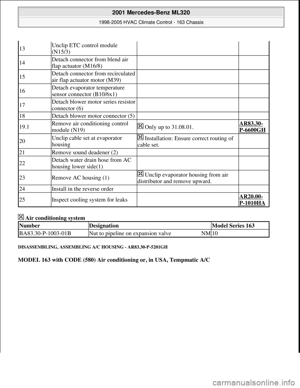
Air conditioning system
DISASSEMBLING, ASSEMBLING A/C HOUSING - AR83.30-P-5201GH
MODEL 163 with CODE (580) Air conditioning or, in USA, Tempmatic A/C
13Unclip ETC control module
(N15/3)
14Detach connector from blend air
flap actuator (M16/8)
15Detach connector from recirculated
air flap actuator motor (M39)
16Detach evaporator temperature
sensor connector (B10/6x1)
17Detach blower motor series resistor
connector (6)
18Detach blower motor connector (5)
19.1Remove air conditioning control
module (N19) Only up to 31.08.01.AR83.30-
P-6600GH
20Unclip cable set at evaporator
housing Installation: Ensure correct routing of
cable set.
21Remove sound deadener (2)
22Detach water drain hose from AC
housing lower side(1)
23Remove AC housing (1) Unclip evaporator housing from air
distributor and remove upward.
24Install in the reverse order
25Inspect cooling system for leaks AR20.00-
P-1010HA
NumberDesignationModel Series 163
BA83.30-P-1003-01BNut to pipeline on expansion valveNM10
2001 Mercedes-Benz ML320
1998-2005 HVAC Climate Control - 163 Chassis
me
Saturday, October 02, 2010 3:23:18 PMPage 198 © 2006 Mitchell Repair Information Company, LLC.