cooling MERCEDES-BENZ ML320 1997 Complete Manual PDF
[x] Cancel search | Manufacturer: MERCEDES-BENZ, Model Year: 1997, Model line: ML320, Model: MERCEDES-BENZ ML320 1997Pages: 4133, PDF Size: 88.89 MB
Page 3169 of 4133
provide reliable cooling system protection. In special cases (commercial-vehicle engines, no antifreeze
specification) coolant additives can be used that are primarily corrosion protection additives. In this case
item 2.3 is valid.
As an exception, if neither anticorrosion/antifreeze agent conforming to Sheet 325.0 nor coolant additives
without addition of antifreeze conforming to Sheet 312.0 are available, proceed according to point 2.4
(exception: OM 500 and OM 900). The systems described under items 2.2/2.3/2.4 are not compatible
with each other. It is recommended to mix the entire coolant quantity outside the engine.
2.1 Anticorrosion/antifreeze agent for passenger-car engines
Alongside the correct constitution of the cooling water (point 1.2.2), care must be taken to ensure that
only anticorrosion/antifreeze agents as approved for all engines in accordance with Sheet 325.0 are used.
These products serve to guarantee that, in particular, an effective protection against corrosion is provided
for all light-alloy parts in the cooling system and they are also specified for all passenger-car engines.
In order to ensure that the protection against corrosion is effective, the anticorrosion/antifreeze agent must
remain in the cooling system throughout the year - including when in tropical climates - and regardless of
the operating conditions. In countries with high outside temperatures this is also important in terms of
raising the boiling point.
In the event that these regulations are not observed the cooling system may suffer from damage by
corrosion. As a consequence of corrosion deposits there is a danger that ducts in the radiators (engine
overheating) and heat exchangers (poor heat output) get plugged up thus causing damage to the engine.
As a result of the optimizations we have carried out on the system of engine/coolant/cooling system, in
the majority of our newer passenger cars, a replacement of coolant is not necessary until reaching 15
operating years or 250,000 km (whichever comes first). This may not apply to some models; in these
cases the maintenance booklet will stipulate another regulation.
2.2 Anticorrosion/antifreeze agent for commercial-vehicle engines (normal case)
(not: BR 600, BR 100 and BR 200)
The coolant in commercial-vehicle engines is made up of both water and anticorrosion/antifreeze agent
(refer to item 1.1.1) and as such offers ideal protection against corrosion and cavitation.
All the approved products on the Sheets 325.2, 325.3 or 325.0 which are part of the Specifications for
Operating Fluids can be used to select an anticorrosion/antifreeze agent. However, it should be noted that
passenger vehicle engines built into commercial vehicles must be filled like passenger vehicles (e.g. OM
601 in T1), i.e. a product conforming to Sheet 325.0 and 326.0 must be used.
Products that are not listed in Sheets 325.0 and 326.0, or 325.2 and 326.2, or 325.3 and 326.3 are not
approved and are therefore not to be used under any circumstances.
Anticorrosion/antifreeze agents or coolants conforming to Sheet 325.3 or 326.3 may be used for
longer than other products due to their composition. The change interval is set at 5 years (refer to
2004 Mercedes-Benz ML350
1998-2005 GENINFO Overall vehicle - 163 Chassis
me
Saturday, October 02, 2010 3:47:57 PMPage 524 © 2006 Mitchell Repair Information Company, LLC.
Page 3171 of 4133
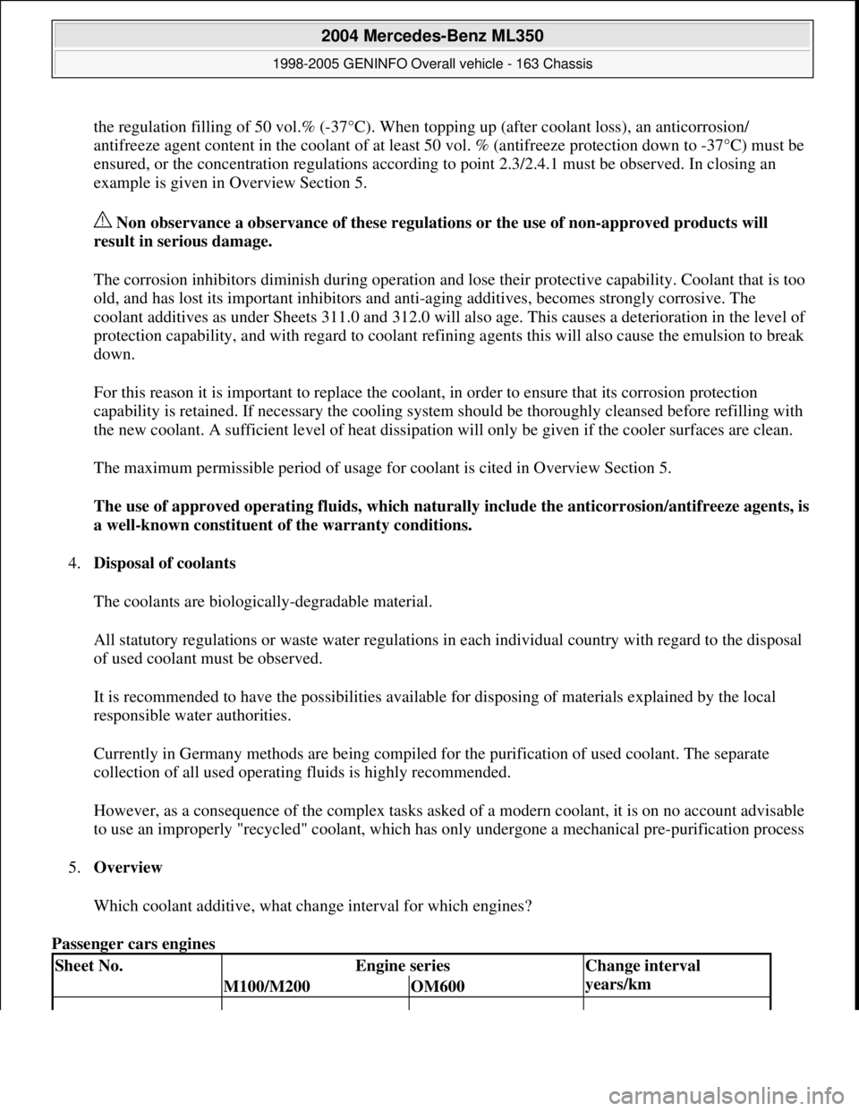
the regulation filling of 50 vol.% (-37°C). When topping up (after coolant loss), an anticorrosion/
antifreeze agent content in the coolant of at least 50 vol. % (antifreeze protection down to -37°C) must be
ensured, or the concentration regulations according to point 2.3/2.4.1 must be observed. In closing an
example is given in Overview Section 5.
Non observance a observance of these regulations or the use of non-approved products will
result in serious damage.
The corrosion inhibitors diminish during operation and lose their protective capability. Coolant that is too
old, and has lost its important inhibitors and anti-aging additives, becomes strongly corrosive. The
coolant additives as under Sheets 311.0 and 312.0 will also age. This causes a deterioration in the level of
protection capability, and with regard to coolant refining agents this will also cause the emulsion to break
down.
For this reason it is important to replace the coolant, in order to ensure that its corrosion protection
capability is retained. If necessary the cooling system should be thoroughly cleansed before refilling with
the new coolant. A sufficient level of heat dissipation will only be given if the cooler surfaces are clean.
The maximum permissible period of usage for coolant is cited in Overview Section 5.
The use of approved operatin
g fluids, which naturally include the anticorrosion/antifreeze agents, is
a well-known constituent of the warranty conditions.
4.Disposal of coolants
The coolants are biologically-degradable material.
All statutory regulations or waste water regulations in each individual country with regard to the disposal
of used coolant must be observed.
It is recommended to have the possibilities available for disposing of materials explained by the local
responsible water authorities.
Currently in Germany methods are being compiled for the purification of used coolant. The separate
collection of all used operating fluids is highly recommended.
However, as a consequence of the complex tasks asked of a modern coolant, it is on no account advisable
to use an improperly "recycled" coolant, which has only undergone a mechanical pre-purification process
5.Overview
Which coolant additive, what change interval for which engines?
Passenger cars engines
Sheet No.Engine seriesChange interval
years/km
M100/M200OM600
2004 Mercedes-Benz ML350
1998-2005 GENINFO Overall vehicle - 163 Chassis
me
Saturday, October 02, 2010 3:47:57 PMPage 526 © 2006 Mitchell Repair Information Company, LLC.
Page 3174 of 4133
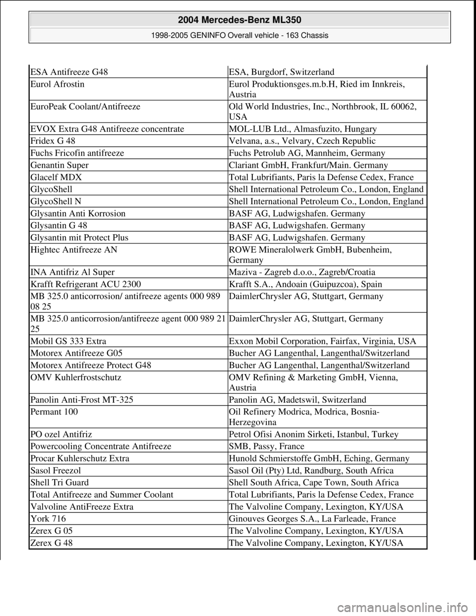
ESA Antifreeze G48ESA, Burgdorf, Switzerland
Eurol AfrostinEurol Produktionsges.m.b.H, Ried im Innkreis,
Austria
EuroPeak Coolant/AntifreezeOld World Industries, Inc., Northbrook, IL 60062,
USA
EVOX Extra G48 Antifreeze concentrateMOL-LUB Ltd., Almasfuzito, Hungary
Fridex G 48Velvana, a.s., Velvary, Czech Republic
Fuchs Fricofin antifreezeFuchs Petrolub AG, Mannheim, Germany
Genantin SuperClariant GmbH, Frankfurt/Main. Germany
Glacelf MDXTotal Lubrifiants, Paris la Defense Cedex, France
GlycoShellShell International Petroleum Co., London, England
GlycoShell NShell International Petroleum Co., London, England
Glysantin Anti KorrosionBASF AG, Ludwigshafen. Germany
Glysantin G 48BASF AG, Ludwigshafen. Germany
Glysantin mit Protect PlusBASF AG, Ludwigshafen. Germany
Hightec Antifreeze ANROWE Mineralolwerk GmbH, Bubenheim,
Germany
INA Antifriz Al SuperMaziva - Zagreb d.o.o., Zagreb/Croatia
Krafft Refrigerant ACU 2300Krafft S.A., Andoain (Guipuzcoa), Spain
MB 325.0 anticorrosion/ antifreeze agents 000 989
08 25DaimlerChrysler AG, Stuttgart, Germany
MB 325.0 anticorrosion/antifreeze agent 000 989 21
25DaimlerChrysler AG, Stuttgart, Germany
Mobil GS 333 ExtraExxon Mobil Corporation, Fairfax, Virginia, USA
Motorex Antifreeze G05Bucher AG Langenthal, Langenthal/Switzerland
Motorex Antifreeze Protect G48Bucher AG Langenthal, Langenthal/Switzerland
OMV KuhlerfrostschutzOMV Refining & Marketing GmbH, Vienna,
Austria
Panolin Anti-Frost MT-325Panolin AG, Madetswil, Switzerland
Permant 100Oil Refinery Modrica, Modrica, Bosnia-
Herzegovina
PO ozel AntifrizPetrol Ofisi Anonim Sirketi, Istanbul, Turkey
Powercooling Concentrate AntifreezeSMB, Passy, France
Procar Kuhlerschutz ExtraHunold Schmierstoffe GmbH, Eching, Germany
Sasol FreezolSasol Oil (Pty) Ltd, Randburg, South Africa
Shell Tri GuardShell South Africa, Cape Town, South Africa
Total Antifreeze and Summer CoolantTotal Lubrifiants, Paris la Defense Cedex, France
Valvoline AntiFreeze ExtraThe Valvoline Company, Lexington, KY/USA
York 716Ginouves Georges S.A., La Farleade, France
Zerex G 05The Valvoline Company, Lexington, KY/USA
Zerex G 48The Valvoline Company, Lexington, KY/USA
2004 Mercedes-Benz ML350
1998-2005 GENINFO Overall vehicle - 163 Chassis
me
Saturday, October 02, 2010 3:47:57 PMPage 529 © 2006 Mitchell Repair Information Company, LLC.
Page 3214 of 4133
Mode control knob controls air distribution throughout the passenger compartment. Air distribution doors are
controlled by cables activated by the mode control knob. See Fig. 1
. Four mode positions are available with
detents in-between to adjust airflow for personal comfort.
Defrost
Set mode control knob to 12-o'clock position. Air will exit from defrost outlets and side window vents.
Vent
Set mode control knob to 9-o'clock position. Air will exit from instrument panel outlets.
Floor
Set mode control knob to 6-o'clock position. Air will exit from floor outlets.
Blend/Bi-Level
Set mode control knob to 3-o'clock position. Air will exit from defrost, instrument panel, and floor outlets.
TEMPERATURE CONTROL KNOB
Air temperature is controlled by a variable resistor rotary control switch. See Fig. 1 . Switch receives voltage
signal and depending upon position, controls voltage signal sent to air mix damper door motor. See Fig. 2
.
Volta
ge controls position of motor for heating and cooling.
2001 Mercedes-Benz ML320
2000-01 MANUAL A/C-HEATER SYSTEMS ML 320, ML 430 & ML 55
me
Saturday, October 02, 2010 3:25:10 PMPage 3 © 2006 Mitchell Repair Information Company, LLC.
Page 3225 of 4133
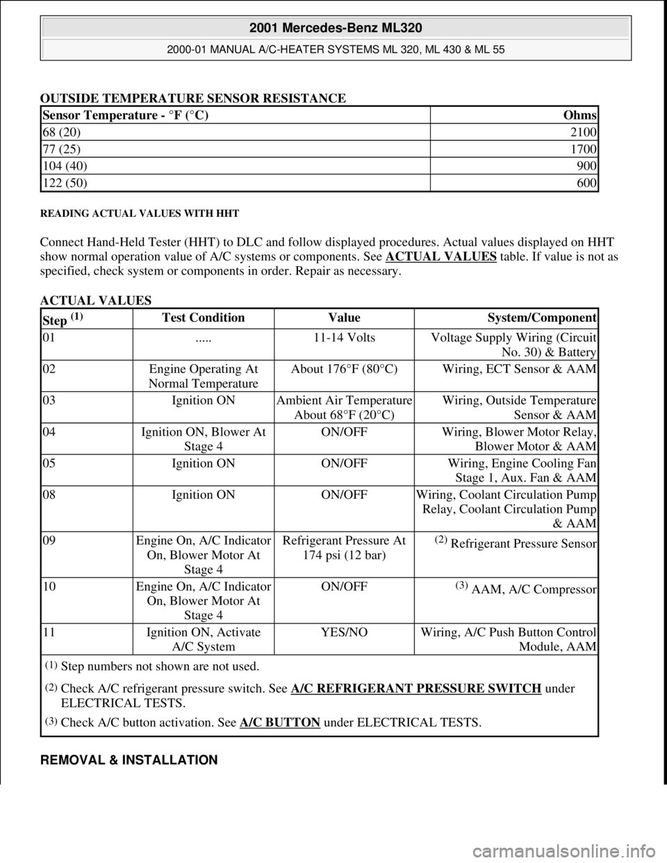
OUTSIDE TEMPERATURE SENSOR RESISTANCE
READING ACTUAL VALUES WITH HHT
Connect Hand-Held Tester (HHT) to DLC and follow displayed procedures. Actual values displayed on HHT
show normal operation value of A/C systems or components. See ACTUAL VALUES
table. If value is not as
specified, check system or components in order. Repair as necessary.
ACTUAL VALUES
REMOVAL & INSTALLATION
Sensor Temperature - °F (°C)Ohms
68 (20)2100
77 (25)1700
104 (40)900
122 (50)600
Step (1) Test ConditionValueSystem/Component
01.....11-14 VoltsVoltage Supply Wiring (Circuit
No. 30) & Battery
02Engine Operating At
Normal TemperatureAbout 176°F (80°C)Wiring, ECT Sensor & AAM
03Ignition ONAmbient Air Temperature
About 68°F (20°C)Wiring, Outside Temperature
Sensor & AAM
04Ignition ON, Blower At
Stage 4ON/OFFWiring, Blower Motor Relay,
Blower Motor & AAM
05Ignition ONON/OFFWiring, Engine Cooling Fan
Stage 1, Aux. Fan & AAM
08Ignition ONON/OFFWiring, Coolant Circulation Pump
Relay, Coolant Circulation Pump
& AAM
09Engine On, A/C Indicator
On, Blower Motor At
Stage 4Refrigerant Pressure At
174 psi (12 bar)(2) Refrigerant Pressure Sensor
10Engine On, A/C Indicator
On, Blower Motor At
Stage 4ON/OFF(3) AAM, A/C Compressor
11Ignition ON, Activate
A/C SystemYES/NOWiring, A/C Push Button Control
Module, AAM
(1)Step numbers not shown are not used.
(2)Check A/C refrigerant pressure switch. See A/C REFRIGERANT PRESSURE SWITCH under
ELECTRICAL TESTS.
(3)Check A/C button activation. See A/C BUTTON under ELECTRICAL TESTS.
2001 Mercedes-Benz ML320
2000-01 MANUAL A/C-HEATER SYSTEMS ML 320, ML 430 & ML 55
me
Saturday, October 02, 2010 3:25:10 PMPage 14 © 2006 Mitchell Repair Information Company, LLC.
Page 3228 of 4133
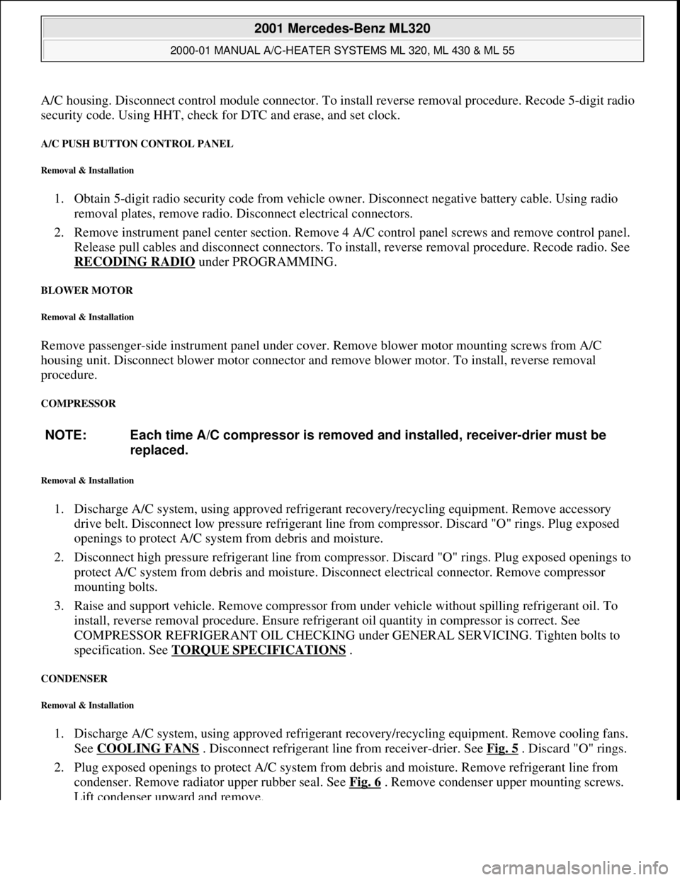
A/C housing. Disconnect control module connector. To install reverse removal procedure. Recode 5-digit radio
security code. Using HHT, check for DTC and erase, and set clock.
A/C PUSH BUTTON CONTROL PANEL
Removal & Installation
1. Obtain 5-digit radio security code from vehicle owner. Disconnect negative battery cable. Using radio
removal plates, remove radio. Disconnect electrical connectors.
2. Remove instrument panel center section. Remove 4 A/C control panel screws and remove control panel.
Release pull cables and disconnect connectors. To install, reverse removal procedure. Recode radio. See
RECODING RADIO
under PROGRAMMING.
BLOWER MOTOR
Removal & Installation
Remove passenger-side instrument panel under cover. Remove blower motor mounting screws from A/C
housing unit. Disconnect blower motor connector and remove blower motor. To install, reverse removal
procedure.
COMPRESSOR
Removal & Installation
1. Discharge A/C system, using approved refrigerant recovery/recycling equipment. Remove accessory
drive belt. Disconnect low pressure refrigerant line from compressor. Discard "O" rings. Plug exposed
openings to protect A/C system from debris and moisture.
2. Disconnect high pressure refrigerant line from compressor. Discard "O" rings. Plug exposed openings to
protect A/C system from debris and moisture. Disconnect electrical connector. Remove compressor
mounting bolts.
3. Raise and support vehicle. Remove compressor from under vehicle without spilling refrigerant oil. To
install, reverse removal procedure. Ensure refrigerant oil quantity in compressor is correct. See
COMPRESSOR REFRIGERANT OIL CHECKING under GENERAL SERVICING. Tighten bolts to
specification. See TORQUE SPECIFICATIONS
.
CONDENSER
Removal & Installation
1. Discharge A/C system, using approved refrigerant recovery/recycling equipment. Remove cooling fans.
See COOLING FANS
. Disconnect refrigerant line from receiver-drier. See Fig. 5 . Discard "O" rings.
2. Plug exposed openings to protect A/C system from debris and moisture. Remove refrigerant line from
condenser. Remove radiator upper rubber seal. See Fig. 6
. Remove condenser upper mounting screws.
Lift condenser upward and remove. NOTE: Each time A/C compressor is removed and installed, receiver-drier must be
replaced.
2001 Mercedes-Benz ML320
2000-01 MANUAL A/C-HEATER SYSTEMS ML 320, ML 430 & ML 55
me
Saturday, October 02, 2010 3:25:10 PMPage 17 © 2006 Mitchell Repair Information Company, LLC.
Page 3232 of 4133
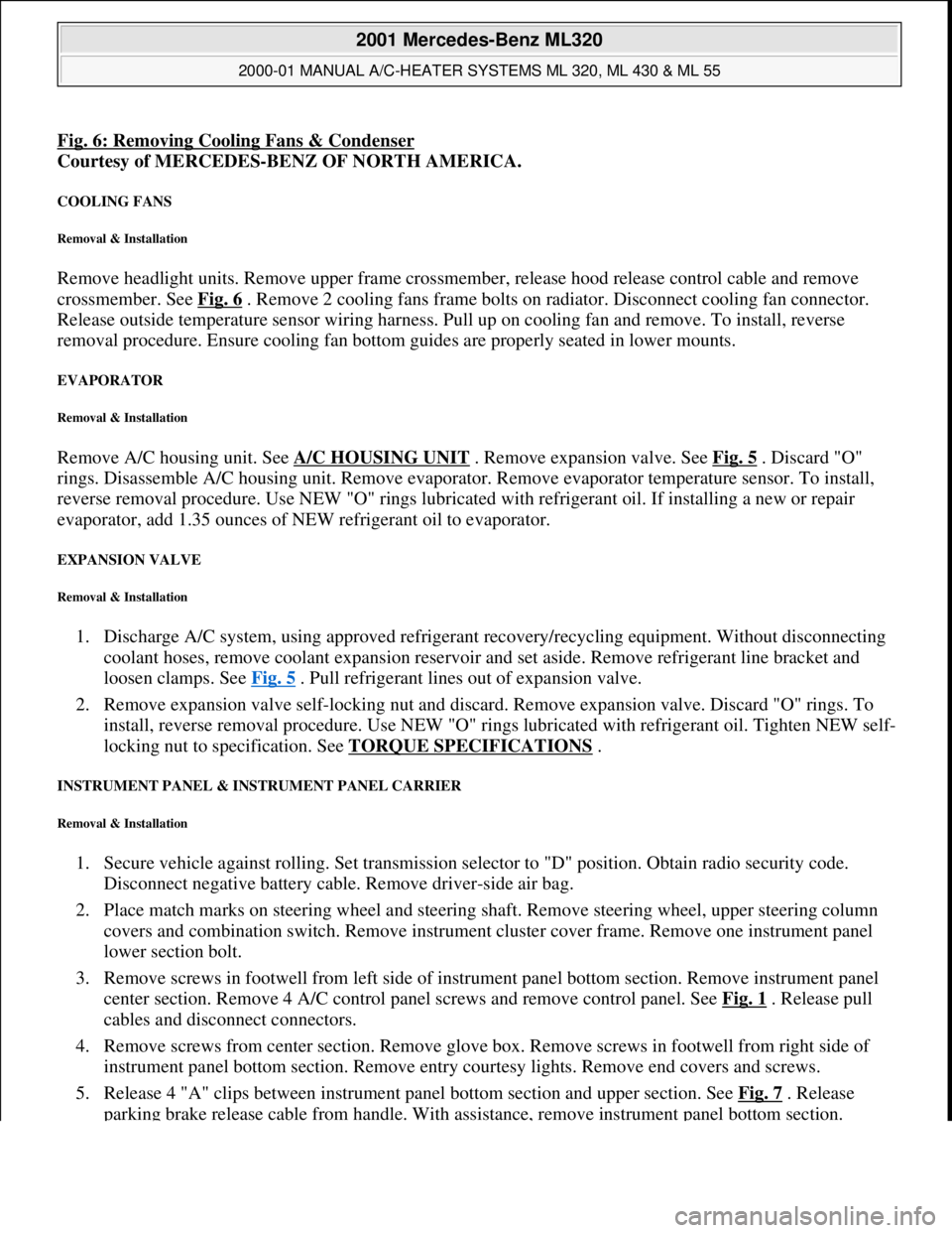
Fig. 6: Removing Cooling Fans & Condenser
Courtesy of MERCEDES-BENZ OF NORTH AMERICA.
COOLING FANS
Removal & Installation
Remove headlight units. Remove upper frame crossmember, release hood release control cable and remove
crossmember. See Fig. 6
. Remove 2 cooling fans frame bolts on radiator. Disconnect cooling fan connector.
Release outside temperature sensor wiring harness. Pull up on cooling fan and remove. To install, reverse
removal procedure. Ensure cooling fan bottom guides are properly seated in lower mounts.
EVAPORATOR
Removal & Installation
Remove A/C housing unit. See A/C HOUSING UNIT . Remove expansion valve. See Fig. 5 . Discard "O"
rings. Disassemble A/C housing unit. Remove evaporator. Remove evaporator temperature sensor. To install,
reverse removal procedure. Use NEW "O" rings lubricated with refrigerant oil. If installing a new or repair
evaporator, add 1.35 ounces of NEW refrigerant oil to evaporator.
EXPANSION VALVE
Removal & Installation
1. Discharge A/C system, using approved refrigerant recovery/recycling equipment. Without disconnecting
coolant hoses, remove coolant expansion reservoir and set aside. Remove refrigerant line bracket and
loosen clamps. See Fig. 5
. Pull refrigerant lines out of expansion valve.
2. Remove expansion valve self-locking nut and discard. Remove expansion valve. Discard "O" rings. To
install, reverse removal procedure. Use NEW "O" rings lubricated with refrigerant oil. Tighten NEW self-
locking nut to specification. See TORQUE SPECIFICATIONS
.
INSTRUMENT PANEL & INSTRUMENT PANEL CARRIER
Removal & Installation
1. Secure vehicle against rolling. Set transmission selector to "D" position. Obtain radio security code.
Disconnect negative battery cable. Remove driver-side air bag.
2. Place match marks on steering wheel and steering shaft. Remove steering wheel, upper steering column
covers and combination switch. Remove instrument cluster cover frame. Remove one instrument panel
lower section bolt.
3. Remove screws in footwell from left side of instrument panel bottom section. Remove instrument panel
center section. Remove 4 A/C control panel screws and remove control panel. See Fig. 1
. Release pull
cables and disconnect connectors.
4. Remove screws from center section. Remove glove box. Remove screws in footwell from right side of
instrument panel bottom section. Remove entry courtesy lights. Remove end covers and screws.
5. Release 4 "A" clips between instrument panel bottom section and upper section. See Fig. 7
. Release
parkin
g brake release cable from handle. With assistance, remove instrument panel bottom section.
2001 Mercedes-Benz ML320
2000-01 MANUAL A/C-HEATER SYSTEMS ML 320, ML 430 & ML 55
me
Saturday, October 02, 2010 3:25:10 PMPage 21 © 2006 Mitchell Repair Information Company, LLC.
Page 3238 of 4133
Fig. 10: Manual A/C-Heater Systems Wiring Diagram (2000-01 ML 320 Without Cooling Fan Control
Module - 1 Of 2)
2001 Mercedes-Benz ML320
2000-01 MANUAL A/C-HEATER SYSTEMS ML 320, ML 430 & ML 55
me
Saturday, October 02, 2010 3:25:10 PMPage 27 © 2006 Mitchell Repair Information Company, LLC.
Page 3240 of 4133
Fig. 11: Manual A/C-Heater Systems Wiring Diagram (2000-01 ML 320 Without Cooling Fan Control
Module - 2 Of 2)
2001 Mercedes-Benz ML320
2000-01 MANUAL A/C-HEATER SYSTEMS ML 320, ML 430 & ML 55
me
Saturday, October 02, 2010 3:25:10 PMPage 29 © 2006 Mitchell Repair Information Company, LLC.
Page 3242 of 4133
Fig. 12: Automatic A/C-Heater Systems Wiring Diagram (2000-01 ML 320 & ML 430 With Cooling Fan
Control Module - 1 Of 2)
2001 Mercedes-Benz ML320
2000-01 MANUAL A/C-HEATER SYSTEMS ML 320, ML 430 & ML 55
me
Saturday, October 02, 2010 3:25:10 PMPage 31 © 2006 Mitchell Repair Information Company, LLC.