parking brake MERCEDES-BENZ ML320 1997 Complete Repair Manual
[x] Cancel search | Manufacturer: MERCEDES-BENZ, Model Year: 1997, Model line: ML320, Model: MERCEDES-BENZ ML320 1997Pages: 4133, PDF Size: 88.89 MB
Page 3496 of 4133
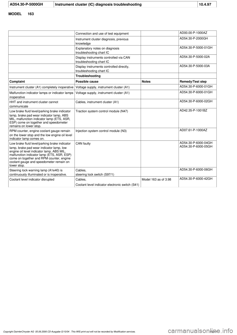
AD54.30-P-5000GH
Instrument cluster (IC) diagnosis troubleshooting
10.4.97
MODEL
163
Connection and use of test equipment
AD00.00-P-1000AZ
Instrument cluster diagnosis, previous
knowledge
AD54.30-P-2000GH
Explanatory notes on diagnosis
troubleshooting chart IC
AD54.30-P-5000-01GH
Display instruments controlled via CAN
troubleshooting chart IC
AD54.30-P-5000-02A
Display instruments controlled directly,
troubleshooting chart IC
AD54.30-P-5000-03A
Troubleshooting
Complaint
Possible cause
Notes
Remedy/Test step
Instrument cluster (A1) completely inoperative
Voltage supply, instrument cluster (A1)
AD54.30-P-6000-01GH
Malfunction indicator lamps or indicator lamps
inoperative
Voltage supply, instrument cluster (A1)
AD54.30-P-6000-01GH
HHT and instrument cluster cannot
communicate
Cables, instrument cluster (A1)
AD54.30-P-6000-02GH
Low brake fluid level/parking brake indicator
lamp, brake pad wear indicator lamp, ABS
MIL, malfunction indicator lamp (ETS, ASR,
ESP) come on together and speedometer
remains on lower stop.
Traction system control module (N47)
AD42.35-P-1001BZ
RPM counter, engine coolant gauge remain
on the lower stop and the low engine oil level
indicator lamp comes on.
Injection system control module (N3)
AD07.61-P-1000AZ
Low brake fluid level/parking brake indicator
lamp, brake pad wear indicator lamp, low
engine oil level indicator lamp, ABS MIL,
malfunction indicator lamp (ETS, ASR, ESP)
come on together and RPM counter, engine
coolant gauge and speedometer remain on
lower stop.
CAN faulty
AD54.30-P-6000-04GH
AD54.30-P-6000-05GH
Steering lock warning lamp (A1e40) is
continuously illuminated or is inoperative.
Cables,
steering lock switch (S97/1)
AD54.30-P-6000-06GH
Coolant level indicator disrupted
Cables,
Coolant level indicator electronic switch (S41)
Model 163 as of 3.98
AD54.30-P-6000-42GH
Copyright DaimlerChrysler AG 05.06.2006 CD-Ausgabe G/10/04 . This WIS print-out will not be recorde
d by Modification services.
Page 1
Page 3499 of 4133
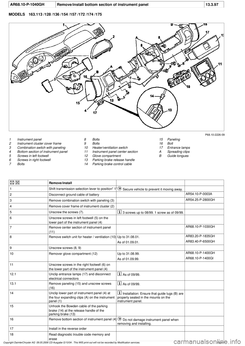
AR68.10-P-1040GH
Remove/install bottom section of instrument panel
13.3.97
MODELS
163.113 /128 /136 /154 /157 /172 /174 /175
P68.10-2226-09
1
Instrument panel
2
Instrument cluster cover frame
3
Combination switch with paneling
4
Bottom section of instrument panel
5
Screws in left footwell
6
Screws in right footwell
7
Bolts
15
Paneling
16
Bolt
17
Entrance lamps
A
Spreading clips
B
Guide tongues
8
Bolts
9
Bolts
10
Heater/ventilation switch
11
Instrument panel center section
12
Glove compartment
13
Parking brake release handle
14
Parking brake control cable
Remove/install
1
Shift transmission selection lever to position" 1"
Secure vehicle to prevent it moving away.
2
Disconnect ground cable of battery
AR54.10-P-0003A
3
Remove combination switch with paneling (3)
AR54.25-P-2800GH
4
Remove cover frame of instrument cluster (2)
5
Unscrew the screws (7).
3 screws up to 08/99. 1 screw as of 09/99.
6
Unscrew screws in left footwell (5) on the
lower part of the instrument panel (4)
7
Remove center section of instrument panel
(11)
AR68.10-P-1030GH
8
Remove switch unit for heater / ventilation (10)
Up to 31.08.01.
AR83.20-P-1835GH
As of 01.09.01.
AR83.40-P-6500GH
9
Unscrew screws (8, 9)
10
Remover glove compartment (12)
Up to 31.08.99.
AR68.10-P-1400GH
As of 01.09.99.
AR68.10-P-1400GI
11
Unscrew screws in the right footwell (6) on
the lower part of the instrument panel (4)
12.1
Unclip entrance lamps (17) and disconnect
electrical connectors
As of 09/99.
13.1
Remove paneling (15) and unscrew screws
(16)
As of 09/99.
14
Unclip lower part of instrument panel (4) at
the four expanding clips (A) on the instrument
panel (1)
Installation: Ensure that guide lugs (B) are
properly seated in the mounts on the
instrument panel.
15
Unhook the Bowden cable of the parking
brake (14) at the release handle of the
parking brake (13)
16
Remove bottom section of instrument panel (4)
Do not damage instrument panel when
removing and installing.
17
Install in the reverse order
18
Read diagnostic trouble code memory and
erase
Copyright DaimlerChrysler AG 09.05.2006 CD-Ausgabe G/10/04 . This WIS print-out will not be recorde
d by Modification services.
Page 1
Page 3539 of 4133
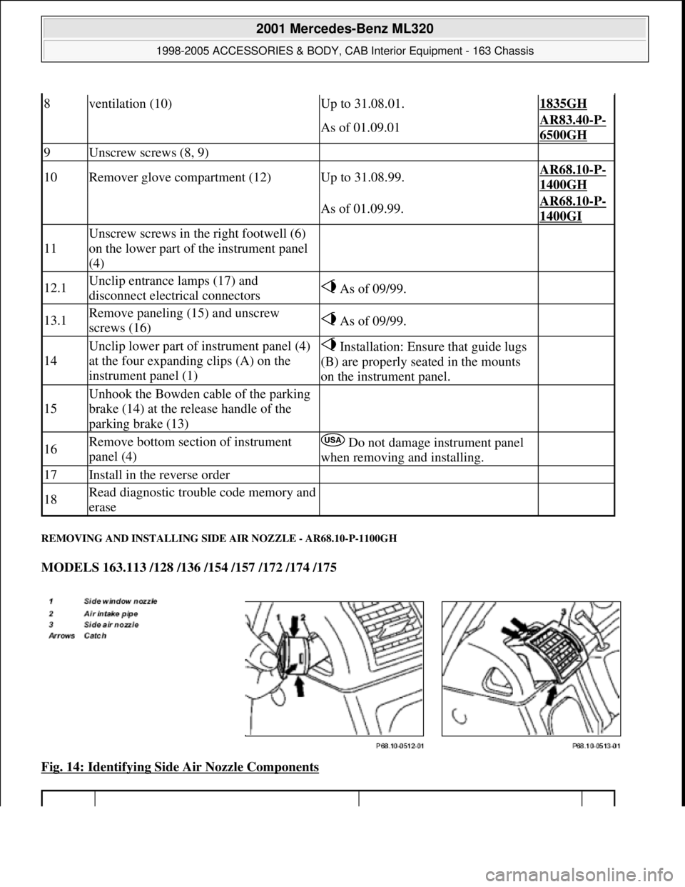
REMOVING AND INSTALLING SIDE AIR NOZZLE - AR68.10-P-1100GH
MODELS 163.113 /128 /136 /154 /157 /172 /174 /175
Fig. 14: Identifying Side Air Nozzle Components
8ventilation (10)Up to 31.08.01.1835GH
As of 01.09.01AR83.40-P-
6500GH
9Unscrew screws (8, 9)
10Remover glove compartment (12)Up to 31.08.99.AR68.10-P-
1400GH
As of 01.09.99.AR68.10-P-
1400GI
11
Unscrew screws in the right footwell (6)
on the lower part of the instrument panel
(4)
12.1Unclip entrance lamps (17) and
disconnect electrical connectors As of 09/99.
13.1Remove paneling (15) and unscrew
screws (16) As of 09/99.
14
Unclip lower part of instrument panel (4)
at the four expanding clips (A) on the
instrument panel (1) Installation: Ensure that guide lugs
(B) are properly seated in the mounts
on the instrument panel.
15
Unhook the Bowden cable of the parking
brake (14) at the release handle of the
parking brake (13)
16Remove bottom section of instrument
panel (4) Do not damage instrument panel
when removing and installing.
17Install in the reverse order
18Read diagnostic trouble code memory and
erase
2001 Mercedes-Benz ML320
1998-2005 ACCESSORIES & BODY, CAB Interior Equipment - 163 Chassis
me
Saturday, October 02, 2010 3:35:21 PMPage 21 © 2006 Mitchell Repair Information Company, LLC.
Page 3553 of 4133

Fig. 29: Identifying Stowage Compartment (Driver's Side Vehicles As Of VIN A145273, X708319)
Remove/install
1Remove left and right cover below instrument cluster Risk of breakage!
2Unscrew bolt (10)
Up to VIN A145272, X708318: 3
screws.
As of VIN A145273, X708319: 1
screw.
3Unscrew screws (9) from bottom side of instrument
panel
4.1Remove entry lamp from bottom of instrument panel Only as of VIN A145273,
X708319.
5.1Remove paneling (8) Only as of VIN A145273,
X708319.
6Unscrew screw (11) from left side of instrument panel
7Loosen instrument panel bottom (2) at side on
instrument panel (1) and pull downward Carefully pull downward to
prevent damaging instrument.
8Unscrew screws (4) from beverage holder (3) at inside
of instrument panel bottom section (2)
9Unscrew screws (5) at outside of instrument panel
bottom section (2) At parking brake release handle
(6).
10Remove beverage holder (3)
2001 Mercedes-Benz ML320
1998-2005 ACCESSORIES & BODY, CAB Interior Equipment - 163 Chassis
me
Saturday, October 02, 2010 3:35:21 PMPage 35 © 2006 Mitchell Repair Information Company, LLC.
Page 3960 of 4133
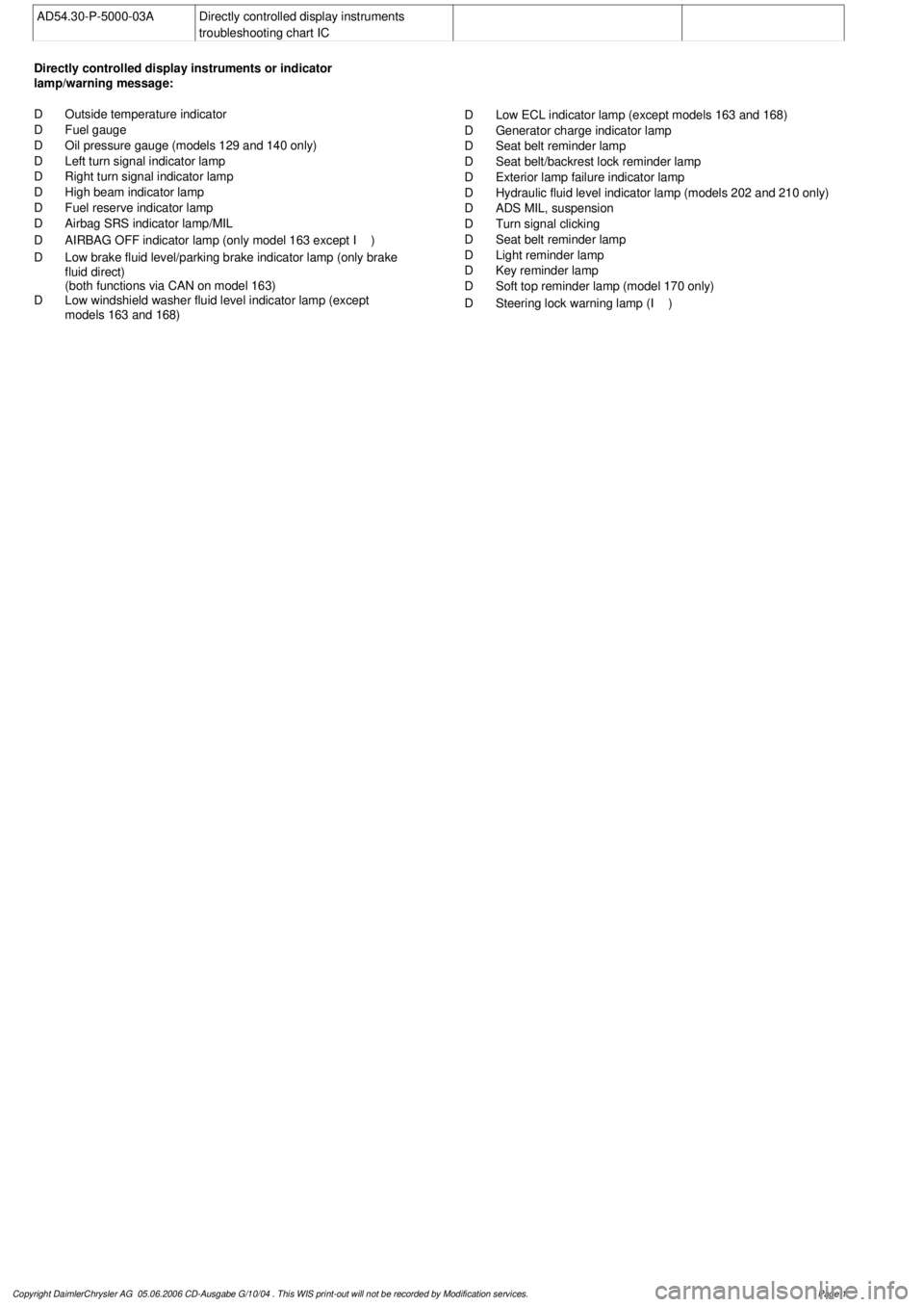
AD54.30-P-5000-03A
Directly controlled display instruments
troubleshooting chart IC
Directly controlled display instruments or indicator
lamp/warning message:
D
Outside temperature indicator
D
Fuel gauge
D
Oil pressure gauge (models 129 and 140 only)
D
Left turn signal indicator lamp
D
Right turn signal indicator lamp
D
High beam indicator lamp
D
Fuel reserve indicator lamp
D
Airbag SRS indicator lamp/MIL
D
AIRBAG OFF indicator lamp (only model 163 except
I )
D
Low brake fluid level/parking brake indicator lamp (only brake
fluid direct)
(both functions via CAN on model 163)
D
Low windshield washer fluid level indicator lamp (except
models 163 and 168)
D
Low ECL indicator lamp (except models 163 and 168)
D
Generator charge indicator lamp
D
Seat belt reminder lamp
D
Seat belt/backrest lock reminder lamp
D
Exterior lamp failure indicator lamp
D
Hydraulic fluid level indicator lamp (models 202 and 210 only)
D
ADS MIL, suspension
D
Turn signal clicking
D
Seat belt reminder lamp
D
Light reminder lamp
D
Key reminder lamp
D
Soft top reminder lamp (model 170 only)
D
Steering lock warning lamp (
I )
Copyright DaimlerChrysler AG 05.06.2006 CD-Ausgabe G/10/04 . This WIS print-out will not be recorde
d by Modification services.
Page 1
Page 3961 of 4133
AD54.30-P-5000-02A
Display instruments controlled via CAN
troubleshooting chart IC
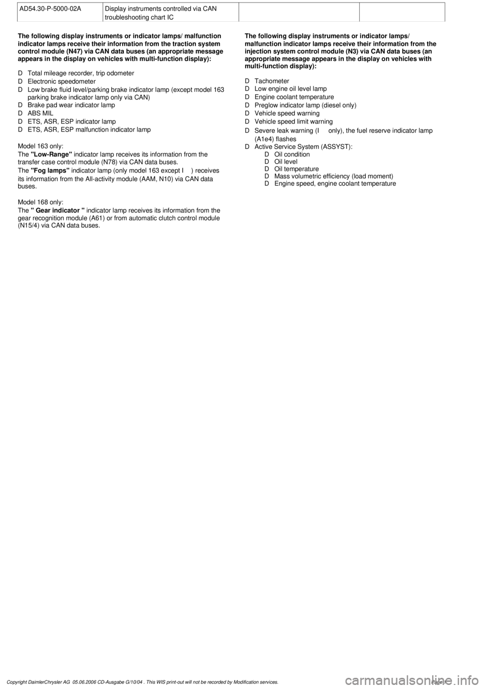
The following display instruments or indicator lamps/ malfunction
indicator lamps receive their information from the traction system
control module (N47) via CAN data buses (an appropriate message
appears in the display on vehicles with multi-function display):
D
Total mileage recorder, trip odometer
D
Electronic speedometer
D
Low brake fluid level/parking brake indicator lamp (except model 163
parking brake indicator lamp only via CAN)
D
Brake pad wear indicator lamp
D
ABS MIL
D
ETS, ASR, ESP indicator lamp
D
ETS, ASR, ESP malfunction indicator lamp
Model 163 only:
The
"Low-Range"
indicator lamp receives its information from the
transfer case control module (N78) via CAN data buses.
The
"Fog lamps"
indicator lamp (only model 163 except
I
) receives
its information from the All-activity module (AAM, N10) via CAN data
buses.
Model 168 only:
The
" Gear indicator "
indicator lamp receives its information from the
gear recognition module (A61) or from automatic clutch control module
(N15/4) via CAN data buses.
The following display instruments or indicator lamps/
malfunction indicator lamps receive their information from the
injection system control module (N3) via CAN data buses (an
appropriate message appears in the display on vehicles with
multi-function display):
D
Tachometer
D
Low engine oil level lamp
D
Engine coolant temperature
D
Preglow indicator lamp (diesel only)
D
Vehicle speed warning
D
Vehicle speed limit warning
D
Severe leak warning (
I
only), the fuel reserve indicator lamp
(A1e4) flashes
D
Active Service System (ASSYST):
D
Oil condition
D
Oil level
D
Oil temperature
D
Mass volumetric efficiency (load moment)
D
Engine speed, engine coolant temperature
Copyright DaimlerChrysler AG 05.06.2006 CD-Ausgabe G/10/04 . This WIS print-out will not be recorde
d by Modification services.
Page 1
Page 3988 of 4133
AD54.30-P-3000-02A
Warning buzzer function check IC
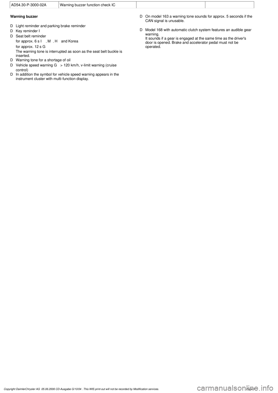
Warning buzzer
D
Light reminder and parking brake reminder
D
Key reminder
I
D
Seat belt reminder
for approx. 6 s
I
,
M
,
H
and Korea
for approx. 12 s
G
The warning tone is interrupted as soon as the seat belt buckle is
inserted.
D
Warning tone for a shortage of oil
D
Vehicle speed warning
G
> 120 km/h, v-limit warning (cruise
control)
D
In addition the symbol for vehicle speed warning appears in the
instrument cluster with multi-function display.
D
On model 163 a warning tone sounds for approx. 5 seconds if the
CAN signal is unusable.
D
Model 168 with automatic clutch system features an audible gear
warning.
It sounds if a gear is engaged at the same time as the driver's
door is opened. Brake and accelerator pedal must not be
operated.
Copyright DaimlerChrysler AG 05.06.2006 CD-Ausgabe G/10/04 . This WIS print-out will not be recorde
d by Modification services.
Page 1