parking brake MERCEDES-BENZ ML320 1997 Complete Manual Online
[x] Cancel search | Manufacturer: MERCEDES-BENZ, Model Year: 1997, Model line: ML320, Model: MERCEDES-BENZ ML320 1997Pages: 4133, PDF Size: 88.89 MB
Page 1208 of 4133
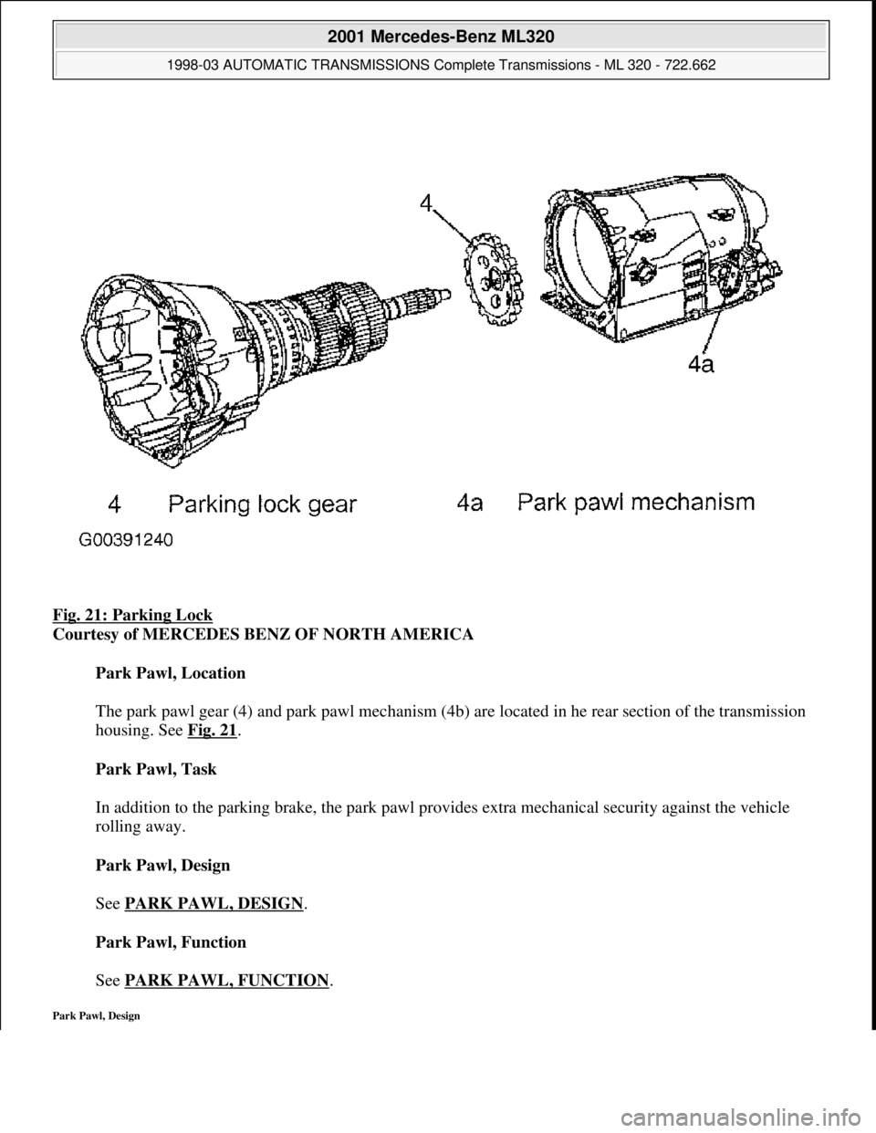
Fig. 21: Parking Lock
Courtesy of MERCEDES BENZ OF NORTH AMERICA
Park Pawl, Location
The park pawl gear (4) and park pawl mechanism (4b) are located in he rear section of the transmission
housing. See Fig. 21
.
Park Pawl, Task
In addition to the parking brake, the park pawl provides extra mechanical security against the vehicle
rolling away.
Park Pawl, Design
See PARK PAWL, DESIGN
.
Park Pawl, Function
See PARK PAWL, FUNCTION
.
Park Pawl, Design
2001 Mercedes-Benz ML320
1998-03 AUTOMATIC TRANSMISSIONS Complete Transmissions - ML 320 - 722.662
me
Saturday, October 02, 2010 3:15:26 PMPage 39 © 2006 Mitchell Repair Information Company, LLC.
Page 1225 of 4133
See MULTIPLE
-DISC BRAKE, LOCATION/TASK/DESIGN/FUNCTION.
Multi-Plate Clutch, Location/Task/Design/Function
See MULTI
-PLATE CLUTCH, LOCATION/TASK/DESIGN/FUNCTION.
Upshift/Downshift Solenoid Valve, Location/Task/Design/Function
See UPSHIFT/DOWNSHIFT SOLENOID VALVE, LOCATION/TASK/DESIGN/FUNCTION
.
Floor Shift, Location/Task/Design/Function
See FLOOR SHIFT, LOCATION/TASK/DESIGN/FUNCTION
.
Location/Task/Design/Function Of Oil Pump
See LOCATION/TASK/DESIGN/FUNCTION OF OIL PUMP
.
Parking Lock, Location/Task/Design/Function
See PARK PAWL, LOCATION/TASK/DESIGN/FUNCTION
.
Planetary Gear Set, Location/Task/Design/Function
See PLANETARY GEAR SET, LOCATION/TASK/DESIGN/FUNCTION
.
Position Indicator, Location/Task/Design/Function
See POSITION DISPLAY, LOCATION TASK
.
Location/Task/Design/Function Of PWM Solenoid Valve, Torque converter Lockup Clutch
See LOCATION/TASK/DESIGN/FUNCTION OF PWM SOLENOID VALVE, TORQUE
CONVERTER LOCKUP CLUTCH.
Modulating Pressure Regulating Solenoid Valve, Location/Task/Design/Function
See MODULATING PRESSURE REGULATING SOLENOID VALVE,
LOCATION/TASK/DESIGN/FUNCTION.
Shift Pressure Regulating Solenoid Valve, Location/Task/Design/Function
See SHIFT PRESSURE REGULATING SOLENOID VALVE,
LOCATION/TASK/DESIGN/FUNCTION.
Working Pressure Regulating Valve, Location/Task/Design/Function
2001 Mercedes-Benz ML320
1998-03 AUTOMATIC TRANSMISSIONS Complete Transmissions - ML 320 - 722.662
me
Saturday, October 02, 2010 3:15:26 PMPage 56 © 2006 Mitchell Repair Information Company, LLC.
Page 1265 of 4133
from flowing from the pressure side to the suction side.
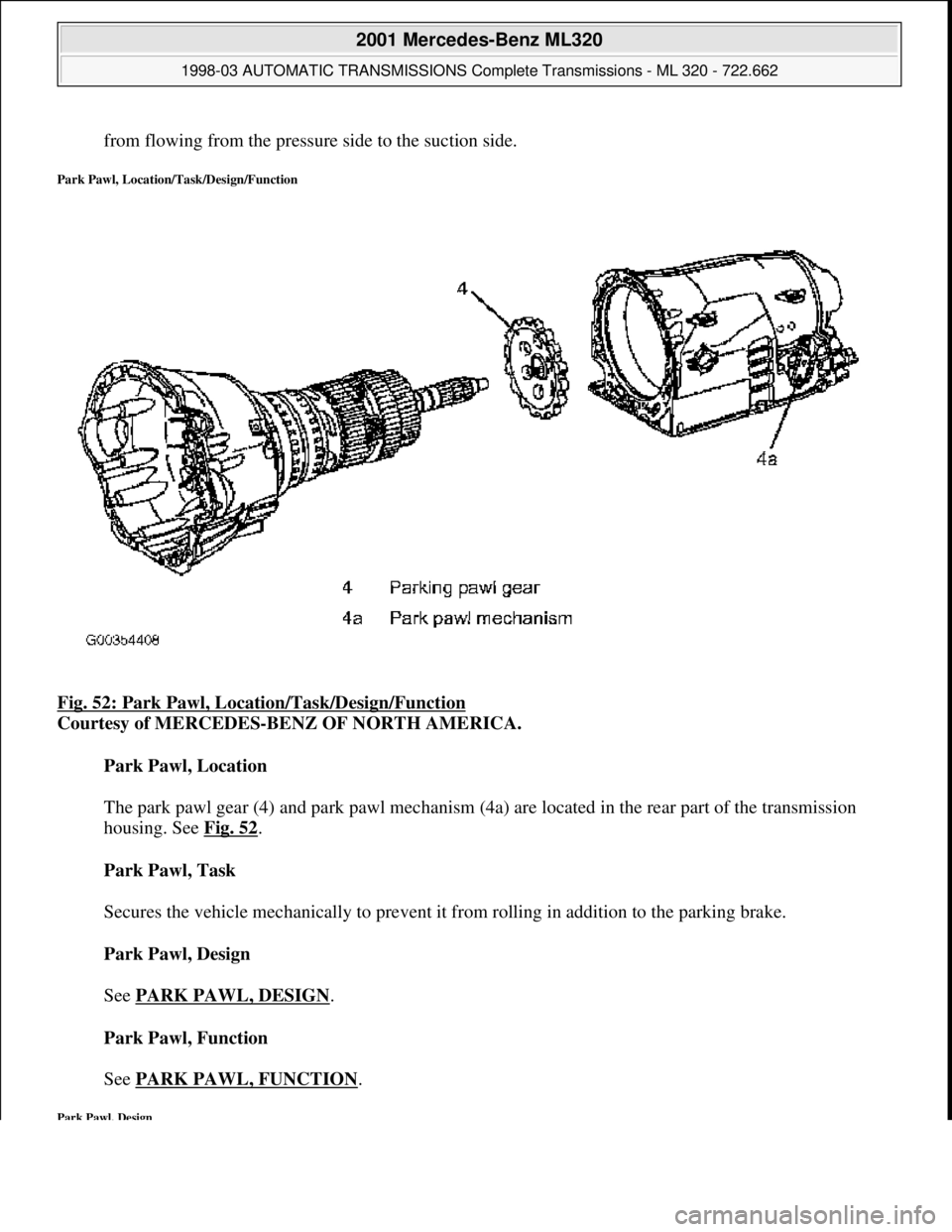
Park Pawl, Location/Task/Design/Function
Fig. 52: Park Pawl, Location/Task/Design/Function
Courtesy of MERCEDES-BENZ OF NORTH AMERICA.
Park Pawl, Location
The park pawl gear (4) and park pawl mechanism (4a) are located in the rear part of the transmission
housing. See Fig. 52
.
Park Pawl, Task
Secures the vehicle mechanically to prevent it from rolling in addition to the parking brake.
Park Pawl, Design
See PARK PAWL, DESIGN
.
Park Pawl, Function
See PARK PAWL, FUNCTION
.
Park Pawl, Design
2001 Mercedes-Benz ML320
1998-03 AUTOMATIC TRANSMI SSIONS Complete Transmissions - ML 320 - 722.662
me
Saturday, October 02, 2010 3:15:26 PMPage 96 © 2006 Mitchell Repair Information Company, LLC.
Page 1352 of 4133
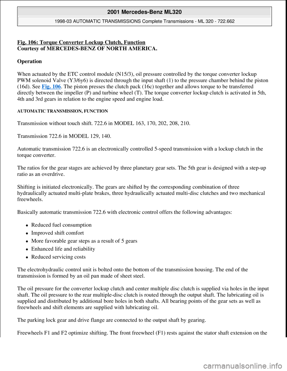
Fig. 106: Torque Converter Lockup Clutch, Function
Courtesy of MERCEDES-BENZ OF NORTH AMERICA.
Operation
When actuated by the ETC control module (N15/3), oil pressure controlled by the torque converter lockup
PWM solenoid Valve (Y3/6y6) is directed through the input shaft (1) to the pressure chamber behind the piston
(16d). See Fig. 106
. The piston presses the clutch pack (16c) together and allows torque to be transferred
directly between the impeller (P) and turbine wheel (T). The torque converter lockup clutch is activated in 5th,
4th and 3rd gears in relation to the engine speed and engine load.
AUTOMATIC TRANSMISSION, FUNCTION
Transmission without touch shift. 722.6 in MODEL 163, 170, 202, 208, 210.
Transmission 722.6 in MODEL 129, 140.
Automatic transmission 722.6 is an electronically controlled 5-speed transmission with a lockup clutch in the
torque converter.
The ratios for the gear stages are achieved by three planetary gear sets. The 5th gear is designed with a step-up
ratio as an overdrive.
Shifting is initiated electronically. The gears are shifted by the corresponding combination of three
hydraulically actuated multi-plate brakes, three hydraulically actuated multi-disc clutches and two mechanical
freewheels.
Basically automatic transmission 722.6 with electronic control offers the following advantages:
Reduced fuel consumption
Improved shift comfort
More favorable gear steps as a result of 5 gears
Enhanced life and reliability
Reduced servicing costs
The electrohydraulic control unit is bolted onto the bottom of the transmission housing. The end of the
transmission is formed by an oil pan made of sheet steel.
The oil pressure for the converter lockup clutch and center multiple disc clutch is supplied via holes in the input
shaft. The oil pressure to the rear multiple-disc clutch is routed through the output shaft. The lubricating oil is
supplied and distributed by additional bore holes in both shafts. All bearing points of the gear sets as well as
freewheels and shift elements are supplied with lubricating oil.
The parking lock gear and drive flange are connected to the output shaft by gearing.
Freewheels F1 and F2 optimize shiftin
g. The front freewheel (F1) rests against the stator shaft extension on the
2001 Mercedes-Benz ML320
1998-03 AUTOMATIC TRANSMISSIONS Complete Transmissions - ML 320 - 722.662
me
Saturday, October 02, 2010 3:15:28 PMPage 183 © 2006 Mitchell Repair Information Company, LLC.
Page 1358 of 4133
Fig. 108: Selector Lever Positions
Courtesy of MERCEDES-BENZ OF NORTH AMERICA.
AUTOMATIC TRANSMISSION, FUNCTION
Transmission With Touch Shift 722.6 In Model 163
Transmission 722.6 is an electronically controlled 5-speed transmission with a lockup clutch in the torque
converter.
The ratios for the gear stages are achieved by 3 planetary gearsets. The 5th gear is designed as a low-rev gear
with an overdrive ratio.
Shifting is initiated electronically. The gears are shifted by the corresponding combination of 3 hydraulically
actuated multi-disk brakes, 3 hydraulically actuated multi-disk clutches and 2 mechanical freewheels.
The oil pump as well as the external plate carrier of the front multi-disk brake are bolted to the torque converter
housing.
The mechanical part of the transmission 722.6 consists of a drive shaft, output shaft, a sun gear shaft and 3
planetary sets which are coupled to each other.
The electrohydraulic control unit is screwed onto the transmission housing from below. The end of the
transmission if formed by an oil pan made of sheet steel.
The oil pressure of the torque converter lockup clutch and center multi-disk clutch is supplied via bore holes in
the drive shaft. The oil pressure to the rear multi-disk clutch is supplied via the output shaft. The lubricating oil
is supplied and distributed by additional bore holes in both shafts. Oil is supplied to all bearing points of the
gearsets as well as to the freewheels and shifting elements.
The parking lock gear and drive flange are connected to the output shaft by gearing.
Basically transmission 722.6 with electronic control offers the following advantages:
Reduced fuel consumption.
Greater ease of shifting.
Favorable spacing by 5 gears.
Long service life and high reliability.
Low maintenance costs.
The torque converter housing and transmission housing consist of a light-metal alloy. Both housings are bolted
together and are centered via the external plate carrier of the multi-disk brake at the front. A coated intermediate
panel seals the two components.
Freewheels F1 and F2 optimize shifting. The front freewheel F1 is supported on the extension of the stator shaft
on the transmission end and connects in the lockin
g direction the sun gear of the front planetary gearset with the
2001 Mercedes-Benz ML320
1998-03 AUTOMATIC TRANSMISSIONS Complete Transmissions - ML 320 - 722.662
me
Saturday, October 02, 2010 3:15:28 PMPage 189 © 2006 Mitchell Repair Information Company, LLC.
Page 1457 of 4133
When the kick-down switch (S16/6) is operated via the accelerator pedal a signal is passed on to the ETC
control module (N15/3). Based on this information the ETC control module (N15/3) actuates the solenoid
valves so that the upshifts and downshifts take place at higher engine speed.
Shift-Lock Function
Operation
The term shift lock combines the functions which, in addition to the parking brake, offer an additional safeguard
for the vehicle to prevent it moving off unintentionally.
These include the functions of locking the selector lever position "P" and locking the ignition lock as well as the
parking lock in the transmission.
The shift lock function only allows shifting out of selector lever position "P" if the transmitter key (A8/1) has
been turned into the position "Ignition: ON" and the brake pedal is depressed.
In order to ensure that after parking the vehicle the selector lever is shifted into selector lever position "P", the
transmitter key (A8/1) can only be turned towards "0" in this position and removed from the EZS control
module (N73) (ignition lock locking, function).
The vehicle is secured mechanically by blocking the park pawl gear.
In the event of mechanical or electrical/electronic faults it is possible to unlock selector lever position "P"
manually (shift lock override function).
Function Of Locking Of Selector Lever Position "P"
See FUNCTION OF LOCKING OF SELECTOR LEVER POSITION "P"
.
Ignition Lock Locking, Function
See IGNITION LOCK INTERLOCK
.
Function Of Shift Lock Override
See FUNCTION OF SHIFT LOCK OVERRIDE
.
Function Of Locking Of Selector Lever Position "P" (With Touch Shift)
Operation
2001 Mercedes-Benz ML320
1998-03 AUTOMATIC TRANSMISSIONS Complete Transmissions - ML 320 - 722.662
me
Saturday, October 02, 2010 3:15:30 PMPage 288 © 2006 Mitchell Repair Information Company, LLC.
Page 1459 of 4133
ignition key position Ignition "ON" when the brake pedal is depressed and therefore when the brake lamp
switch (S9/1) is actuated and when selector lever position "P" is recognized.
The R/P locking magnet (89) releases the selector lever thus allowing the selector lever to be moved away from
position "P".
Parking Lock, Location/Task/Design/Function - See PARK PAWL,
LOCATION/TASK/DESIGN/FUNCTION.
Ignition Lock Interlock
Operation
2001 Mercedes-Benz ML320
1998-03 AUTOMATIC TRANSMISSIONS Complete Transmissions - ML 320 - 722.662
me
Saturday, October 02, 2010 3:15:30 PMPage 290 © 2006 Mitchell Repair Information Company, LLC.
Page 1471 of 4133
Basically automatic transmission 722.6 with electronic control offers the following advantages:
Reduced Fuel Consumption
Improved Shift Comfort
More Favorable Gear Steps As A Result Of 5 Gears
Enhanced Life And Reliability
Reduced Servicing Costs
The electrohydraulic control unit is bolted onto the bottom of the transmission housing. The end of the
transmission is formed by an oil pan made of sheet steel.
The oil pressure for the converter lockup clutch and center multiple-disc clutch is supplied via holes in the input
shaft. The oil pressure to the rear multiple-disc clutch is routed through the output shaft. The lubricating oil is
supplied and distributed by additional bore holes in both shafts. All bearing points of the gear sets as well as
freewheels and shift elements are supplied with lubricating oil.
The parking lock gear and drive flange are connected to the output shaft by gearing.
Freewheels F1 and F2 optimize shifting. The front freewheel (F1) rests against the stator shaft extension on the
transmission side and connects the sun gear of the front planetary gear set to the transmission housing in the
locking direction.
The torque converter housing and transmission housing are made of a metal alloy. They are bolted together and
centered via the outer multiple-disc carrier of the multiple-disc brake B1. A coated intermediate panel seals the
two components.
The oil pump and outer multiple-disc carrier of the front multiple-disc brake are bolted to the converter housing.
The mechanical part consists of the propeller shaft, output shaft, a sun gear shaft and three planetary gearsets
which are coupled together.
In transmissions for powerful engines, the planetary gearsets have 4 planetary gears, while for less powerful
engines the front and rear planetary gear system has three planetary gear wheels. The stator shaft is pressed into
this and is secured against turning by a spline.
The rear freewheel F2 connects the sun gear of the center planetary gear set to the sun gear of the rear planetary
gearset in the locking direction.
The electrohydraulic control unit consists of the shift plate made of light alloy for hydraulic control and an
electronic control unit.
The electrical control unit consists of a supporting body made of plastic in which the electrical components are
combined. The shell is screwed to the shift plate. Conductor tracks which are integrated into the shell, connect
the electric components to a plug connector. This 13-pin plug connector forms the connection with the vehicle-
side wiring harness and with the ETC 5 (electronic transmission control) control module (N15/5) via a bayonet
lock.
2001 Mercedes-Benz ML320
1998-03 AUTOMATIC TRANSMISSIONS Complete Transmissions - ML 320 - 722.662
me
Saturday, October 02, 2010 3:15:30 PMPage 302 © 2006 Mitchell Repair Information Company, LLC.
Page 2146 of 4133
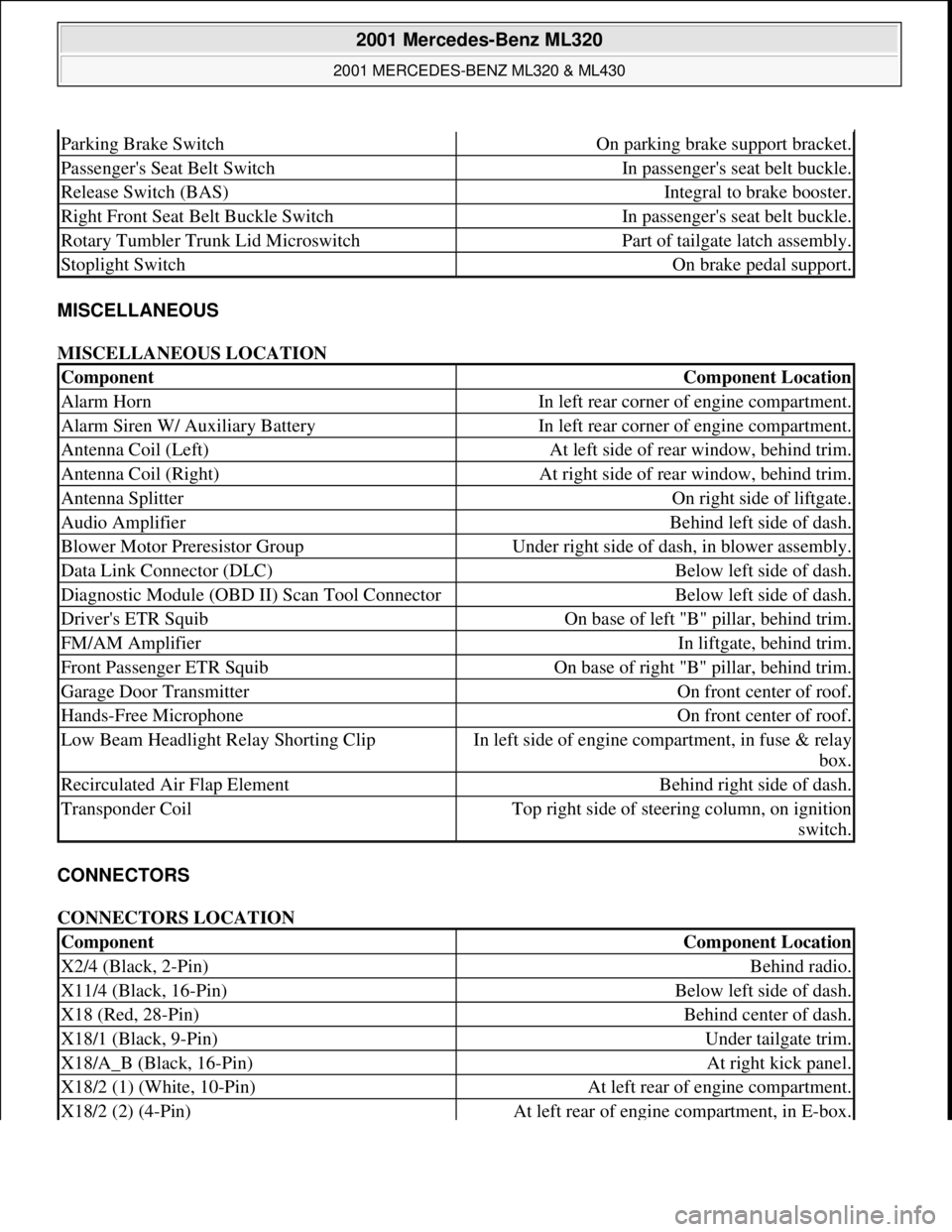
MISCELLANEOUS
MISCELLANEOUS LOCATION
CONNECTORS
CONNECTORS LOCATION
Parking Brake SwitchOn parking brake support bracket.
Passenger's Seat Belt SwitchIn passenger's seat belt buckle.
Release Switch (BAS)Integral to brake booster.
Right Front Seat Belt Buckle SwitchIn passenger's seat belt buckle.
Rotary Tumbler Trunk Lid MicroswitchPart of tailgate latch assembly.
Stoplight SwitchOn brake pedal support.
ComponentComponent Location
Alarm HornIn left rear corner of engine compartment.
Alarm Siren W/ Auxiliary BatteryIn left rear corner of engine compartment.
Antenna Coil (Left)At left side of rear window, behind trim.
Antenna Coil (Right)At right side of rear window, behind trim.
Antenna SplitterOn right side of liftgate.
Audio AmplifierBehind left side of dash.
Blower Motor Preresistor GroupUnder right side of dash, in blower assembly.
Data Link Connector (DLC)Below left side of dash.
Diagnostic Module (OBD II) Scan Tool ConnectorBelow left side of dash.
Driver's ETR SquibOn base of left "B" pillar, behind trim.
FM/AM AmplifierIn liftgate, behind trim.
Front Passenger ETR SquibOn base of right "B" pillar, behind trim.
Garage Door TransmitterOn front center of roof.
Hands-Free MicrophoneOn front center of roof.
Low Beam Headlight Relay Shorting ClipIn left side of engine compartment, in fuse & relay
box.
Recirculated Air Flap ElementBehind right side of dash.
Transponder CoilTop right side of steering column, on ignition
switch.
ComponentComponent Location
X2/4 (Black, 2-Pin)Behind radio.
X11/4 (Black, 16-Pin)Below left side of dash.
X18 (Red, 28-Pin)Behind center of dash.
X18/1 (Black, 9-Pin)Under tailgate trim.
X18/A_B (Black, 16-Pin)At right kick panel.
X18/2 (1) (White, 10-Pin)At left rear of engine compartment.
X18/2 (2) (4-Pin)At left rear of engine compartment, in E-box.
2001 Mercedes-Benz ML320
2001 MERCEDES-BENZ ML320 & ML430
me
Saturday, October 02, 2010 3:21:17 PMPage 6 © 2006 Mitchell Repair Information Company, LLC.
Page 2149 of 4133
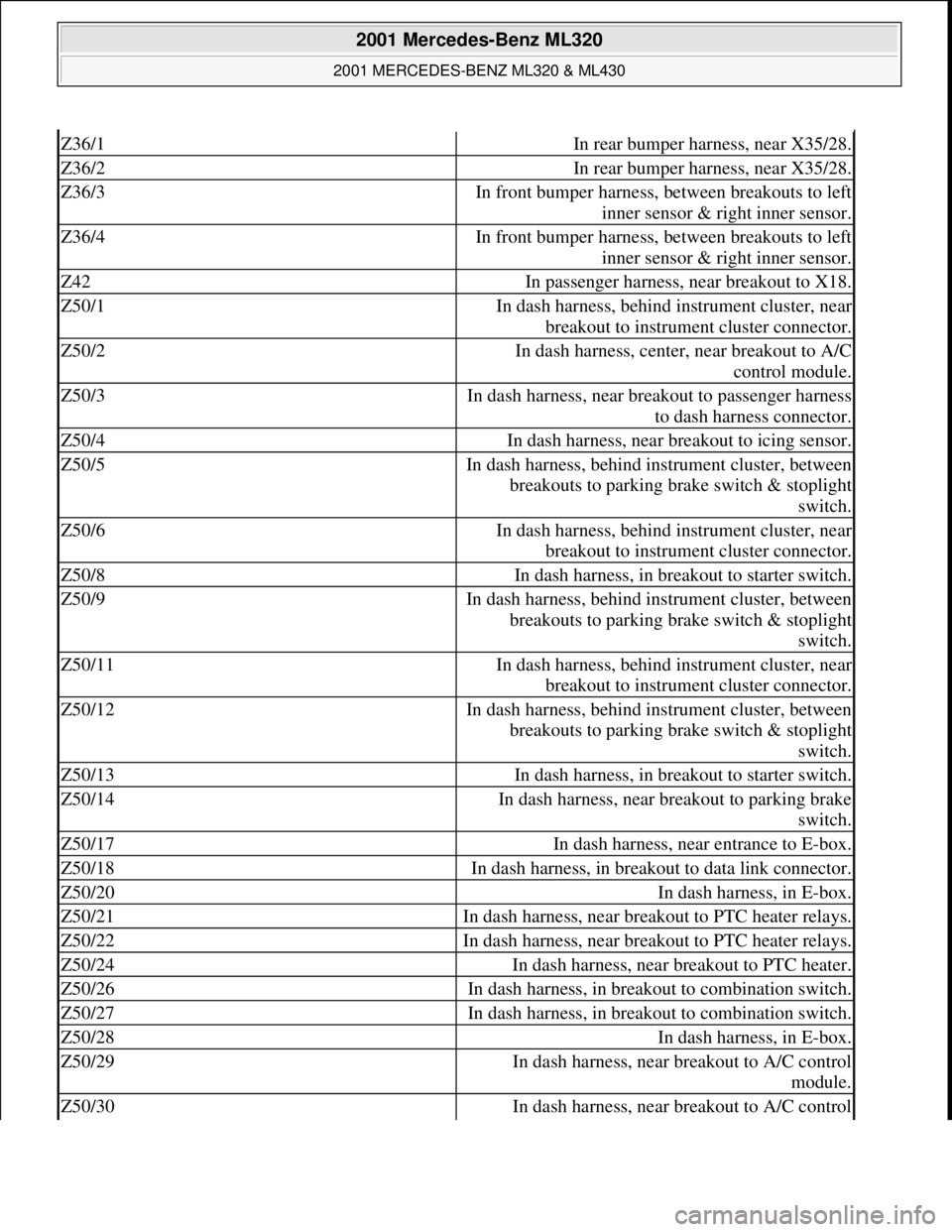
Z36/1In rear bumper harness, near X35/28.
Z36/2In rear bumper harness, near X35/28.
Z36/3In front bumper harness, between breakouts to left
inner sensor & right inner sensor.
Z36/4In front bumper harness, between breakouts to left
inner sensor & right inner sensor.
Z42In passenger harness, near breakout to X18.
Z50/1In dash harness, behind instrument cluster, near
breakout to instrument cluster connector.
Z50/2In dash harness, center, near breakout to A/C
control module.
Z50/3In dash harness, near breakout to passenger harness
to dash harness connector.
Z50/4In dash harness, near breakout to icing sensor.
Z50/5In dash harness, behind instrument cluster, between
breakouts to parking brake switch & stoplight
switch.
Z50/6In dash harness, behind instrument cluster, near
breakout to instrument cluster connector.
Z50/8In dash harness, in breakout to starter switch.
Z50/9In dash harness, behind instrument cluster, between
breakouts to parking brake switch & stoplight
switch.
Z50/11In dash harness, behind instrument cluster, near
breakout to instrument cluster connector.
Z50/12In dash harness, behind instrument cluster, between
breakouts to parking brake switch & stoplight
switch.
Z50/13In dash harness, in breakout to starter switch.
Z50/14In dash harness, near breakout to parking brake
switch.
Z50/17In dash harness, near entrance to E-box.
Z50/18In dash harness, in breakout to data link connector.
Z50/20In dash harness, in E-box.
Z50/21In dash harness, near breakout to PTC heater relays.
Z50/22In dash harness, near breakout to PTC heater relays.
Z50/24In dash harness, near breakout to PTC heater.
Z50/26In dash harness, in breakout to combination switch.
Z50/27In dash harness, in breakout to combination switch.
Z50/28In dash harness, in E-box.
Z50/29In dash harness, near breakout to A/C control
module.
Z50/30In dash harness, near breakout to A/C control
2001 Mercedes-Benz ML320
2001 MERCEDES-BENZ ML320 & ML430
me
Saturday, October 02, 2010 3:21:17 PMPage 9 © 2006 Mitchell Repair Information Company, LLC.