air condition MERCEDES-BENZ ML320 1997 Complete Owner's Manual
[x] Cancel search | Manufacturer: MERCEDES-BENZ, Model Year: 1997, Model line: ML320, Model: MERCEDES-BENZ ML320 1997Pages: 4133, PDF Size: 88.89 MB
Page 301 of 4133
251 Battery
Te ch n ica l
data Instruments
and controlsOperation DrivingInstrument
cluster displayPractical hintsCar care Index If a tire constantly loses air, it should be inspected for
damage.
The spare tire should be checked periodically for
condition and inflation. Spare tire will age and become
worn over time even if never used, and thus should be
inspected and replaced when necessary.Battery
Important!
Battery replacement information:
The maintenance-free battery is located in the engine
compartment.
The service life of the battery is dependent on its
condition of charge. The battery should always be kept
sufficiently charged, in order to last an optimum length
of time.
Wa r n i n g !
Do not overinflate tires. Overinflating tires can
result in sudden deflation (blowout) because they
are more likely to become punctured or damaged
by road debris, potholes etc.. Follow recommended
inflation pressures.Do not overload the tires by exceeding the specified
vehicle capacity weight (as indicated by the label
on the driver’s door latch post). Overloading the
tires can overheat them, possibly causing a
blowout.
Wa r n i n g !
Failure to follow these instructions can result in
severe injury or death.Never lean over batteries while connecting, you
might get injured.Battery fluid contains sulfuric acid. Do not allow
this fluid to come in contact with eyes, skin or
clothing. In case it does, immediately flush affected
area with water and seek medical help if necessary.A battery will also produce hydrogen gas, which is
flammable and explosive. Keep flames or sparks
away from battery, avoid improper connection of
jumper cables, smoking etc..
Page 328 of 4133
278 Cleaning and care of the vehicle
Te ch n ica l
data Instruments
and controlsOperation DrivingInstrument
cluster displayPractical hintsCar careIndex
Cleaning and care of the vehicle
In operation, your vehicle is subjected to varying
external inf luences which, if gone unchecked, can
attack the paintwork as well as the underbody and
cause lasting damage.
Such damage is caused not only by extreme and varying
climatic conditions, but also by air polution, road salt,
tar, gravel and stone chipping. Grease and oil, fuel,
coolant, brake fluid, bird droppings, insects, tree resins
etc. should be removed immediately to avoid paint
damage. Frequent washing reduces and / or eliminates
the aggressiveness and potency of the above adverse
influences.More frequent washings are necessary to deal with
unfavorable conditions; for example, near the ocean, in
industrial areas (smoke, exhaust emissions), or during
winter operation.
You should check your vehicle from time to time for
stone chipping or other damage. Any damage should be
repaired as soon as possible to prevent the start of
corrosion.
In doing so, do not neglect the underside of the vehicle.
A prerequisite for a thorough check is a washing of the
underbody followed by a thorough inspection. Damaged
areas need to be reundercoated.
Your vehicle has been treated at the factory with a wax-
base ru stproof ing in th e body cavities w hich will la st for
the lifetime of the vehicle. Post-production treatment is
neither necessary nor recommended by Mercedes-Benz
because of the possibility of incompatibility between
materials used in the production process and others
applied later.
We have selected car-care products and compiled
recommendations which are specially matched to our
vehicles and which always reflect the latest technology.
You can obtain Mercedes-Benz approved car-care
products at your authorized Mercedes-Benz Light Truck
Center.
Wa r n i n g !
Many cleaning products can be hazardous. Some
are poisonous, others are flammable. Always follow
the instructions on the particular container.
Always open your vehicle’s doors or windows when
cleaning the inside.Never use fluids or solvents that are not designed
for cleaning your vehicle.
Page 333 of 4133
283 Contents - Technical data
Te ch n ica l
data Instruments
and controlsOperation DrivingInstrument
cluster displayPractical hints Car care Index
Technical dataSpare parts service ........................284
Warranty coverage .........................284
Identification labels .......................285
Layout of poly-V-belt drive ............286
Technical data ................................287
Fuels, coolants, lubricants
etc. – capacities .........................292Engine oils ...................................... 294
Engine oil additives ...................... 294
Air conditioner refrigerant .......... 294
Brake fluid ...................................... 294
Premium unleaded gasoline ........ 295
Fuel requirements ........................ 295
Gasoline additives ......................... 296
Coolants .......................................... 296
Consumer information ................. 298
Page 336 of 4133
286 Technical data
Te ch n ica l
data Instruments
and controlsOperation DrivingInstrument
cluster displayPractical hints Car care Index
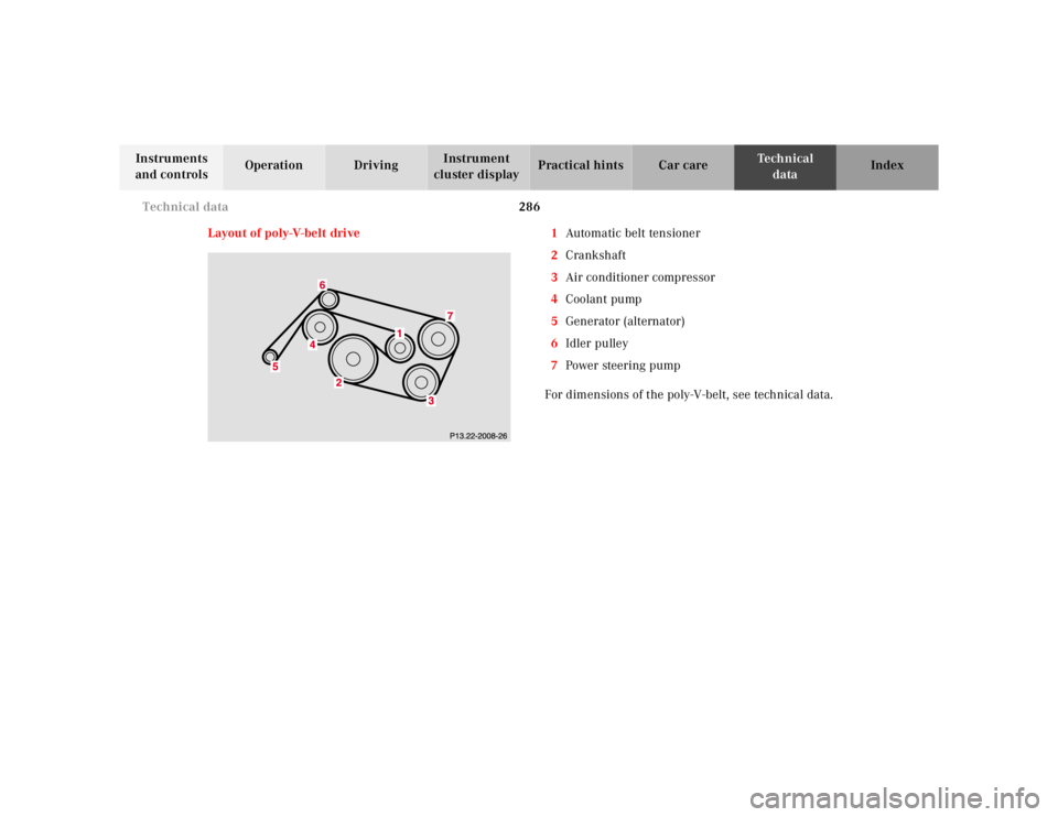
Layout of poly-V-belt drive 1Automatic belt tensioner
2Crankshaft
3Air conditioner compressor
4Coolant pump
5Generator (alternator)
6Idler pulley
7Power steering pump
For dimensions of the poly-V-belt, see technical data.
Page 343 of 4133
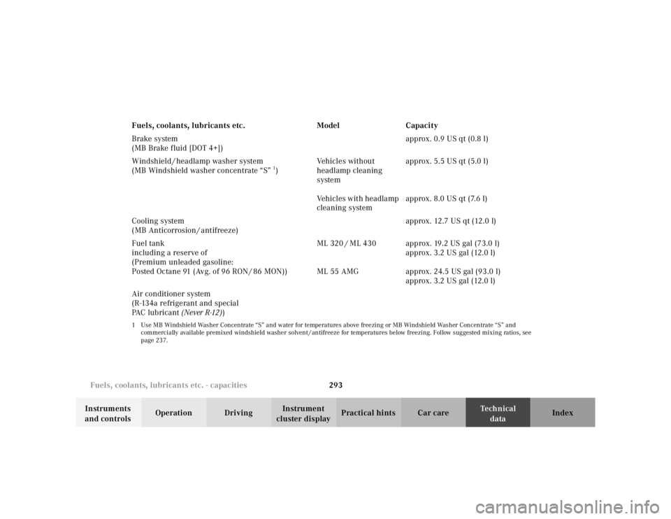
293 Fuels, coolants, lubricants etc. - capacities
Te ch n ica l
data Instruments
and controlsOperation DrivingInstrument
cluster displayPractical hints Car care Index Brake system
(MB Brake fluid [DOT 4+])approx. 0.9 US qt (0.8 l)
Windshield / headlamp washer system
(MB Windshield washer concentrate “S”
1)Vehicles without
headlamp cleaning
system
Vehicles with headlamp
cleaning systemapprox. 5.5 US qt (5.0 l)
approx. 8.0 US qt (7.6 l)
Cooling system
(MB Anticorrosion / antifreeze)approx. 12.7 US qt (12.0 l)
Fuel tank
including a reserve of
(Premium unleaded gasoline:
Posted Octane 91 (Avg. of 96 RON / 86 MON))ML 320 / ML 430
ML 55 AMGapprox. 19.2 US gal (73.0 l)
approx. 3.2 US gal (12.0 l)
approx. 24.5 US gal (93.0 l)
approx. 3.2 US gal (12.0 l)
Air conditioner system
(R-134a refrigerant and special
PA C l u b r i c a n t (Never R-12))
1 Use MB Windshield Washer Concentrate “S” and water for temperatures above freezing or MB Windshield Washer Concentrate “S” and
commercially available premixed windshield washer solvent / antifreeze for temperatures below freezing. Follow suggested mixing ratios, see
page 237.Fuels, coolants, lubricants etc. Model Capacity
Page 344 of 4133
294 Fuels, coolants, lubricants etc.
Te ch n ica l
data Instruments
and controlsOperation DrivingInstrument
cluster displayPractical hints Car care Index
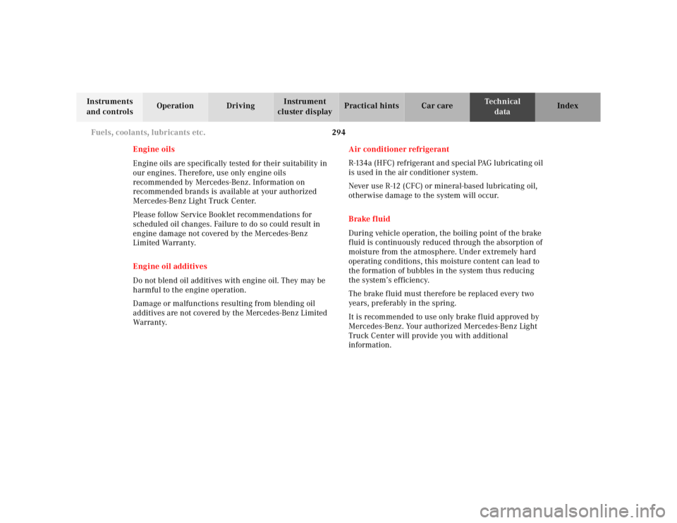
Engine oils
Engine oils are specifically tested for their suitability in
our engines. Therefore, use only engine oils
recommended by Mercedes-Benz. Information on
recommended brands is available at your authorized
Mercedes-Benz Light Truck Center.
Please follow Service Booklet recommendations for
scheduled oil changes. Failure to do so could result in
engine damage not covered by the Mercedes-Benz
Limited Warranty.
Engine oil additives
Do not blend oil additives with engine oil. They may be
harmful to the engine operation.
Damage or malfunctions resulting from blending oil
additives are not covered by the Mercedes-Benz Limited
War ra nt y.Air conditioner refrigerant
R-134a (HFC) refrigerant and special PAG lubricating oil
is used in the air conditioner system.
Never use R-12 (CFC) or mineral-based lubricating oil,
otherwise damage to the system will occur.
Brake fluid
During vehicle operation, the boiling point of the brake
fluid is continuously reduced through the absorption of
moisture from the atmosphere. Under extremely hard
operating conditions, this moisture content can lead to
the formation of bubbles in the system thus reducing
the system’s efficiency.
The brake fluid must therefore be replaced every two
years, preferably in the spring.
It is recommended to use only brake fluid approved by
Mercedes-Benz. Your authorized Mercedes-Benz Light
Truck Center will provide you with additional
information.
Page 350 of 4133
300 Index
Te ch n ica l
data Instruments
and controlsOperation DrivingInstrument
cluster displayPractical hints Car careIndex
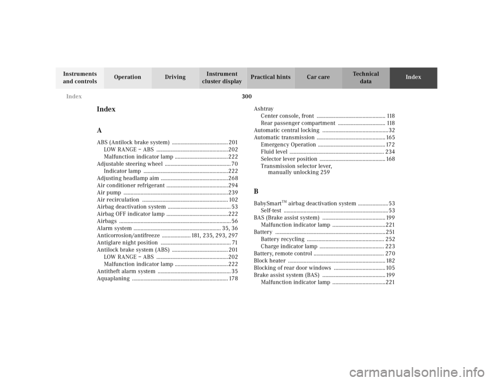
Index
AABS (Antilock brake system) ....................................... 201
LOW RANGE – ABS ..................................................202
Malfunction indicator lamp .....................................222
Adjustable steering wheel .............................................. 70
Indicator lamp ...........................................................222
Adjusting headlamp aim ...............................................268
Air conditioner refrigerant ...........................................294
Air pump .........................................................................239
Air recirculation ............................................................ 102
Airbag deactivation system ............................................ 53
Airbag OFF indicator lamp ...........................................222
Airbags .............................................................................. 56
Alarm system ............................................................. 35, 36
Anticorrosion/antifreeze .................... 181, 235, 293, 297
Antiglare night position ................................................. 71
Antilock brake system (ABS) ....................................... 201
LOW RANGE – ABS ..................................................202
Malfunction indicator lamp .....................................222
Antitheft alarm system ................................................... 35
Aquaplaning ................................................................... 178Ashtray
Center console, front ................................................ 118
Rear passenger compartment ................................. 118
Automatic central locking ..............................................32
Automatic transmission ................................................ 165
Emergency Operation ............................................... 172
Fluid level .................................................................. 234
Selector lever position .............................................. 168
Transmission selector lever,
manually unlocking 259
BBabySmart
TM airbag deactivation system ..................... 53
Self-test ......................................................................... 53
BAS (Brake assist system) ............................................ 199
Malfunction indicator lamp .....................................221
Battery .............................................................................251
Battery recycling ...................................................... 252
Charge indicator lamp ............................................. 223
Battery, remote control ................................................. 270
Block heater .................................................................... 182
Blocking of rear door windows ....................................105
Brake assist system (BAS) ............................................ 199
Malfunction indicator lamp .....................................221
Page 384 of 4133
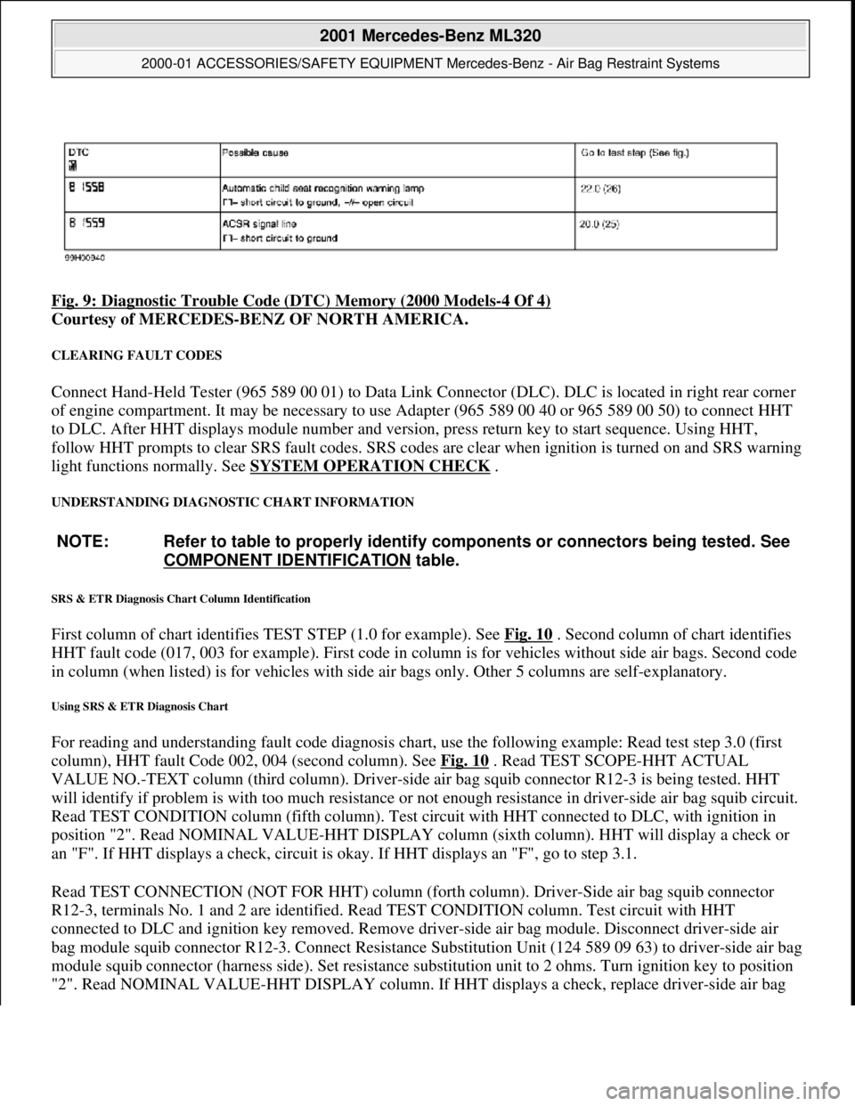
Fig. 9: Diagnostic Trouble Code (DTC) Memory (2000 Models-4 Of 4)
Courtesy of MERCEDES-BENZ OF NORTH AMERICA.
CLEARING FAULT CODES
Connect Hand-Held Tester (965 589 00 01) to Data Link Connector (DLC). DLC is located in right rear corner
of engine compartment. It may be necessary to use Adapter (965 589 00 40 or 965 589 00 50) to connect HHT
to DLC. After HHT displa ys module number and version, press return key to start sequence. Using HHT,
follow HHT prompts to clear SRS faul t codes. SRS codes are clear when ignition is turned on and SRS warning
light functions normally. See SYSTEM OPERATION CHECK
.
UNDERSTANDING DIAGNOSTIC CHART INFORMATION
SRS & ETR Diagnosis Chart Column Identification
First column of chart identifies TEST STEP (1.0 for example). See Fig. 10 . Second column of chart identifies
HHT fault code (017, 003 for example). First code in column is for ve hicles without side air bags. Second code
in column (when listed) is for ve hicles with side air bags only. Ot her 5 columns are self-explanatory.
Using SRS & ETR Diagnosis Chart
For reading and understanding fault code diagnosis chart, use the following example: Read test step 3.0 (first
column), HHT fault Code 002, 004 (second column). See Fig. 10
. Read TEST SCOPE-HHT ACTUAL
VALUE NO.-TEXT column (third column). Driver-side air bag squib connector R12-3 is being tested. HHT
will identify if problem is with too much resistance or not enough resistance in driver-side air bag squib circuit.
Read TEST CONDITION column (fifth column). Test ci rcuit with HHT connected to DLC, with ignition in
position "2". Read NOMINAL VALUE-HHT DISPLAY column (sixth column). HHT will display a check or
an "F". If HHT displays a check, circuit is okay. If HHT displays an "F", go to step 3.1.
Read TEST CONNECTION (NOT FOR HHT) column (fort h column). Driver-Side air bag squib connector
R12-3, terminals No. 1 and 2 are id entified. Read TEST CONDITION column. Test circuit with HHT
connected to DLC and igni tion key removed. Remove driver-side air bag module. Disconnect driver-side air
bag module squib connector R12-3. Conn ect Resistance Substitution Unit (124 589 09 63) to driver-side air bag
module squib connector (harness side). Set resistance substitution unit to 2 ohms. Turn ignition key to position
"2". Read NOMINAL VALUE-HHT DISPLAY column. If HHT displa
ys a check, replace driver-side air bag
NOTE: Refer to table to properly identify components or connectors being tested. See
COMPONENT IDENTIFICATION
table.
2001 Mercedes-Benz ML320
2000-01 ACCESSORIES/SAFETY EQUIPMENT Merc edes-Benz - Air Bag Restraint Systems
me
Saturday, October 02, 2010 3:44:46 PMPage 20 © 2006 Mitchell Repair Information Company, LLC.
Page 385 of 4133
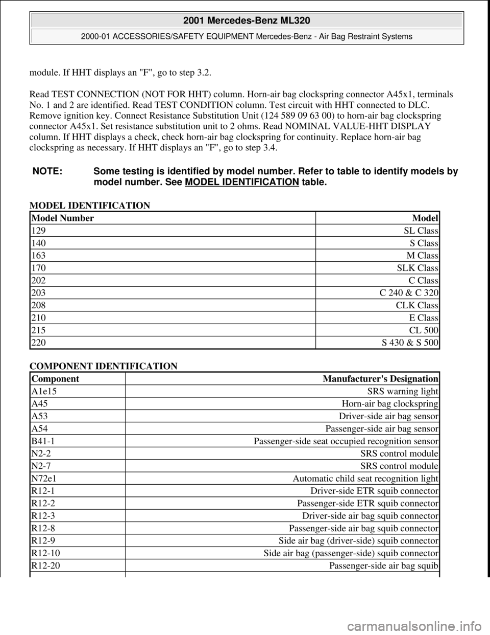
module. If HHT displays an "F", go to step 3.2.
Read TEST CONNECTION (NOT FOR HHT) column. Horn -air bag clockspring connector A45x1, terminals
No. 1 and 2 are identified. Read TEST CONDITION column. Test circuit with HHT connected to DLC.
Remove ignition key. Connect Resist ance Substitution Unit (124 589 09 63 00) to horn-air bag clockspring
connector A45x1. Set resistance s ubstitution unit to 2 ohms. Read NOMINAL VALUE-HHT DISPLAY
column. If HHT displays a check, check horn-air ba g clockspring for continuity. Replace horn-air bag
clockspring as necessary. If HHT displays an "F", go to step 3.4.
MODEL IDENTIFICATION
COMPONENT IDENTIFICATION
NOTE: Some testing is identified
by model number. Refer to table to identify models by
model number. See MO DEL IDENTIFICATION
table.
Model NumberModel
129SL Class
140S Class
163M Class
170SLK Class
202C Class
203C 240 & C 320
208CLK Class
210E Class
215CL 500
220S 430 & S 500
ComponentManufacturer's Designation
A1e15SRS warning light
A45Horn-air bag clockspring
A53Driver-side air bag sensor
A54Passenger-side air bag sensor
B41-1Passenger-side seat occupied recognition sensor
N2-2SRS control module
N2-7SRS control module
N72e1Automatic child seat recognition light
R12-1Driver-side ETR squib connector
R12-2Passenger-side ETR squib connector
R12-3Driver-side air bag squib connector
R12-8Passenger-side air bag squib connector
R12-9Side air bag (driver-side) squib connector
R12-10Side air bag (passenge r-side) squib connector
R12-20Passenger-side air bag squib
2001 Mercedes-Benz ML320
2000-01 ACCESSORIES/SAFETY EQUIPMENT Merc edes-Benz - Air Bag Restraint Systems
me
Saturday, October 02, 2010 3:44:46 PMPage 21 © 2006 Mitchell Repair Information Company, LLC.
Page 386 of 4133
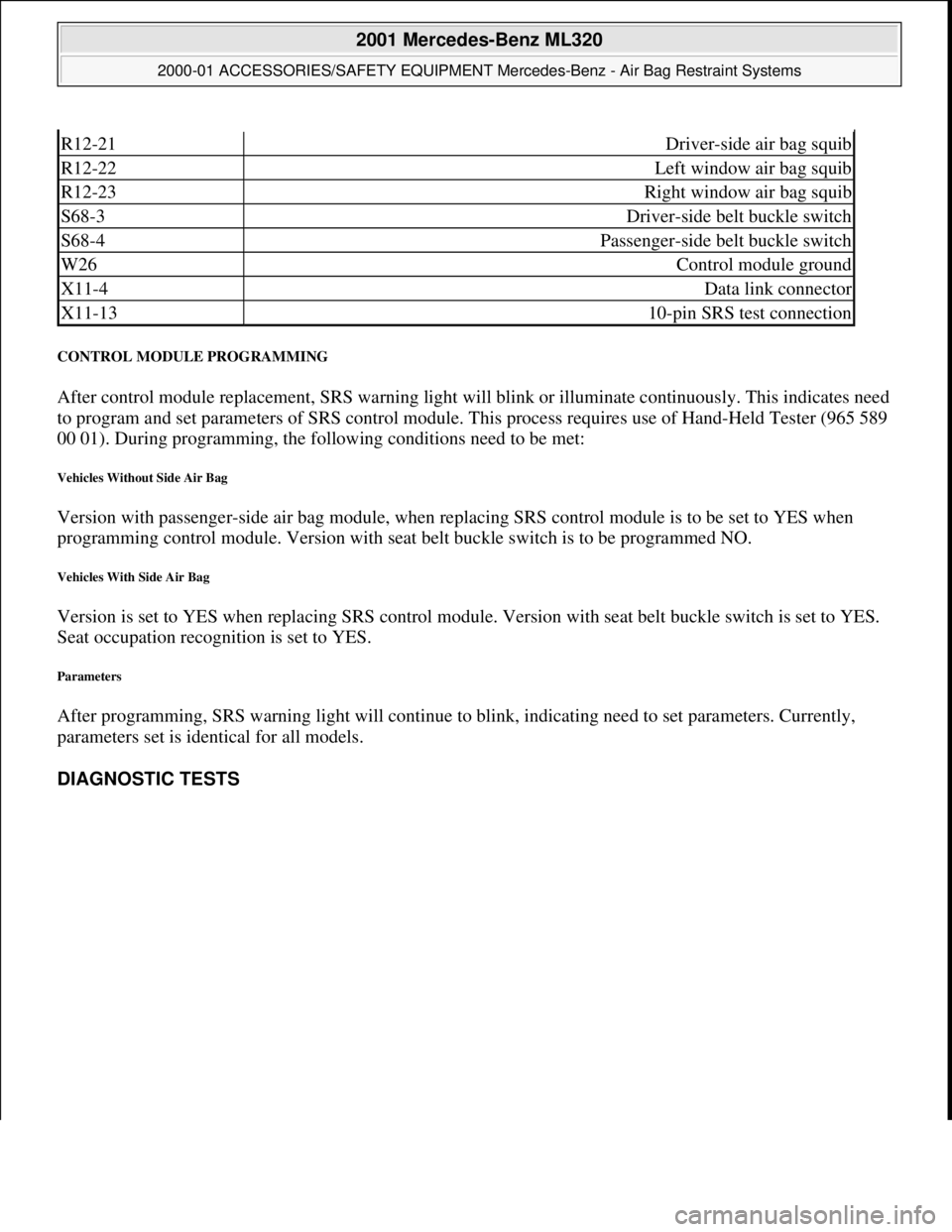
CONTROL MODULE PROGRAMMING
After control module replacement, SRS warning light will blink or illuminate continuously. This indicates need
to program and set paramete rs of SRS control module. This process requires use of Hand-Held Tester (965 589
00 01). During programming, the follow ing conditions need to be met:
Vehicles Without Side Air Bag
Version with passenger-side air bag module, when replac ing SRS control module is to be set to YES when
programming control module. Version with seat belt buckle switch is to be programmed NO.
Vehicles With Side Air Bag
Version is set to YES when replacing SRS control module. Version with seat belt buckle switch is set to YES.
Seat occupation recogni tion is set to YES.
Parameters
After programming, SRS warning light wi ll continue to blink, indicating need to set parameters. Currently,
parameters set is identical for all models.
DIAGNOSTIC TESTS
R12-21Driver-side air bag squib
R12-22Left window air bag squib
R12-23Right window air bag squib
S68-3Driver-side belt buckle switch
S68-4Passenger-side belt buckle switch
W26Control module ground
X11-4Data link connector
X11-1310-pin SRS test connection
2001 Mercedes-Benz ML320
2000-01 ACCESSORIES/SAFETY EQUIPMENT Merc edes-Benz - Air Bag Restraint Systems
me
Saturday, October 02, 2010 3:44:46 PMPage 22 © 2006 Mitchell Repair Information Company, LLC.