oil filter MERCEDES-BENZ ML320 1997 Complete Owner's Manual
[x] Cancel search | Manufacturer: MERCEDES-BENZ, Model Year: 1997, Model line: ML320, Model: MERCEDES-BENZ ML320 1997Pages: 4133, PDF Size: 88.89 MB
Page 2419 of 4133
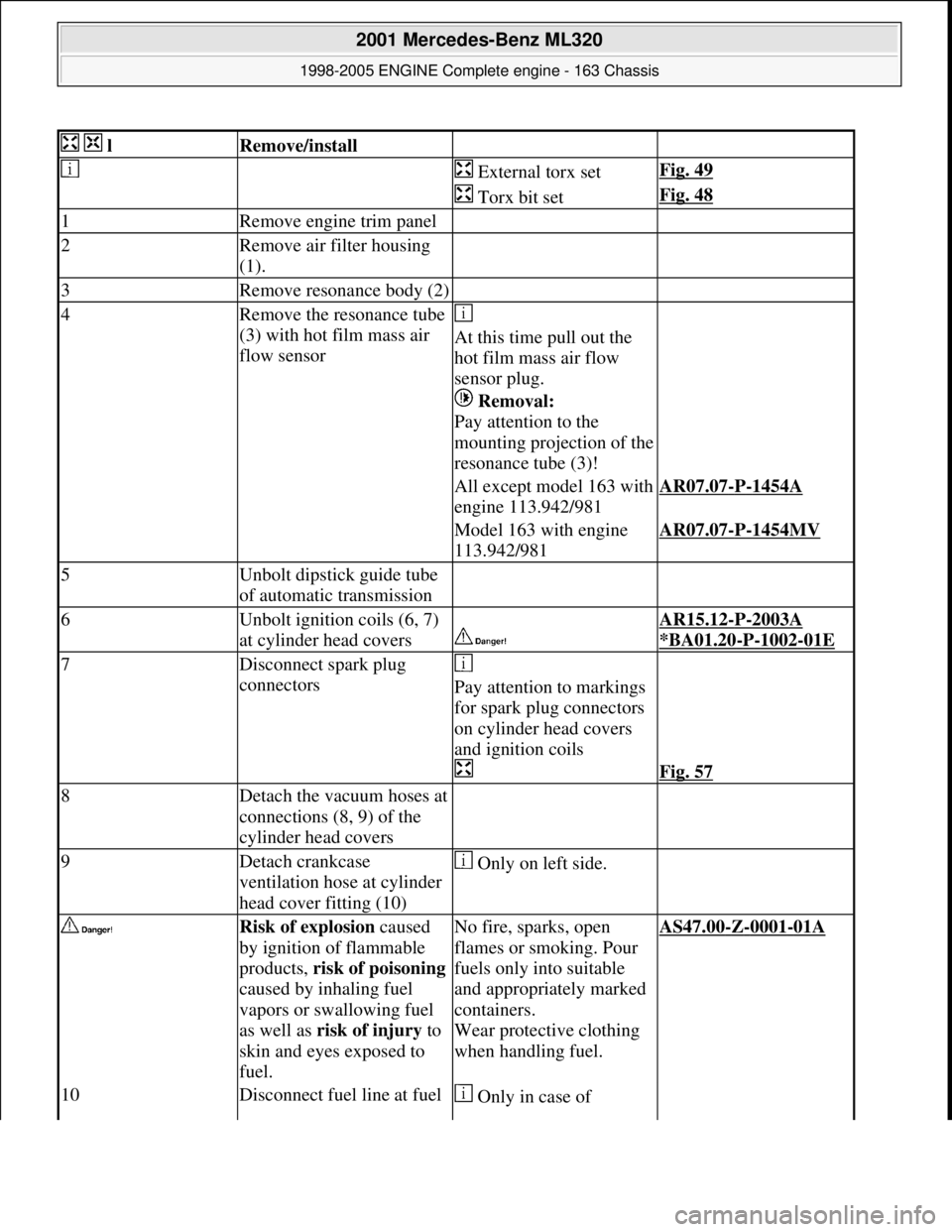
lRemove/install
External torx setFig. 49
Torx bit setFig. 48
1Remove engine trim panel
2Remove air filter housing
(1).
3Remove resonance body (2)
4Remove the resonance tube
(3) with hot film mass air
flow sensor
At this time pull out the
hot film mass air flow
sensor plug.
Removal:
Pay attention to the
mounting projection of the
resonance tube (3)!
All except model 163 with
engine 113.942/981AR07.07-P-1454A
Model 163 with engine
113.942/981AR07.07-P-1454MV
5Unbolt dipstick guide tube
of automatic transmission
6Unbolt ignition coils (6, 7)
at cylinder head covers
AR15.12-P-2003A
*BA01.20
-P-1002-01E
7Disconnect spark plug
connectors
Pay attention to markings
for spark plug connectors
on cylinder head covers
and ignition coils
Fig. 57
8Detach the vacuum hoses at
connections (8, 9) of the
cylinder head covers
9Detach crankcase
ventilation hose at cylinder
head cover fitting (10) Only on left side.
Risk of explosion caused
by ignition of flammable
products, risk of poisoning
caused by inhaling fuel
vapors or swallowing fuel
as well as risk of injury to
skin and eyes exposed to
fuel.No fire, sparks, open
flames or smoking. Pour
fuels only into suitable
and appropriately marked
containers.
Wear protective clothing
when handling fuel.AS47.00-Z-0001-01A
10Disconnect fuel line at fuel Only in case of
2001 Mercedes-Benz ML320
1998-2005 ENGINE Complete engine - 163 Chassis
me
Saturday, October 02, 2010 3:17:56 PMPage 63 © 2006 Mitchell Repair Information Company, LLC.
Page 2423 of 4133
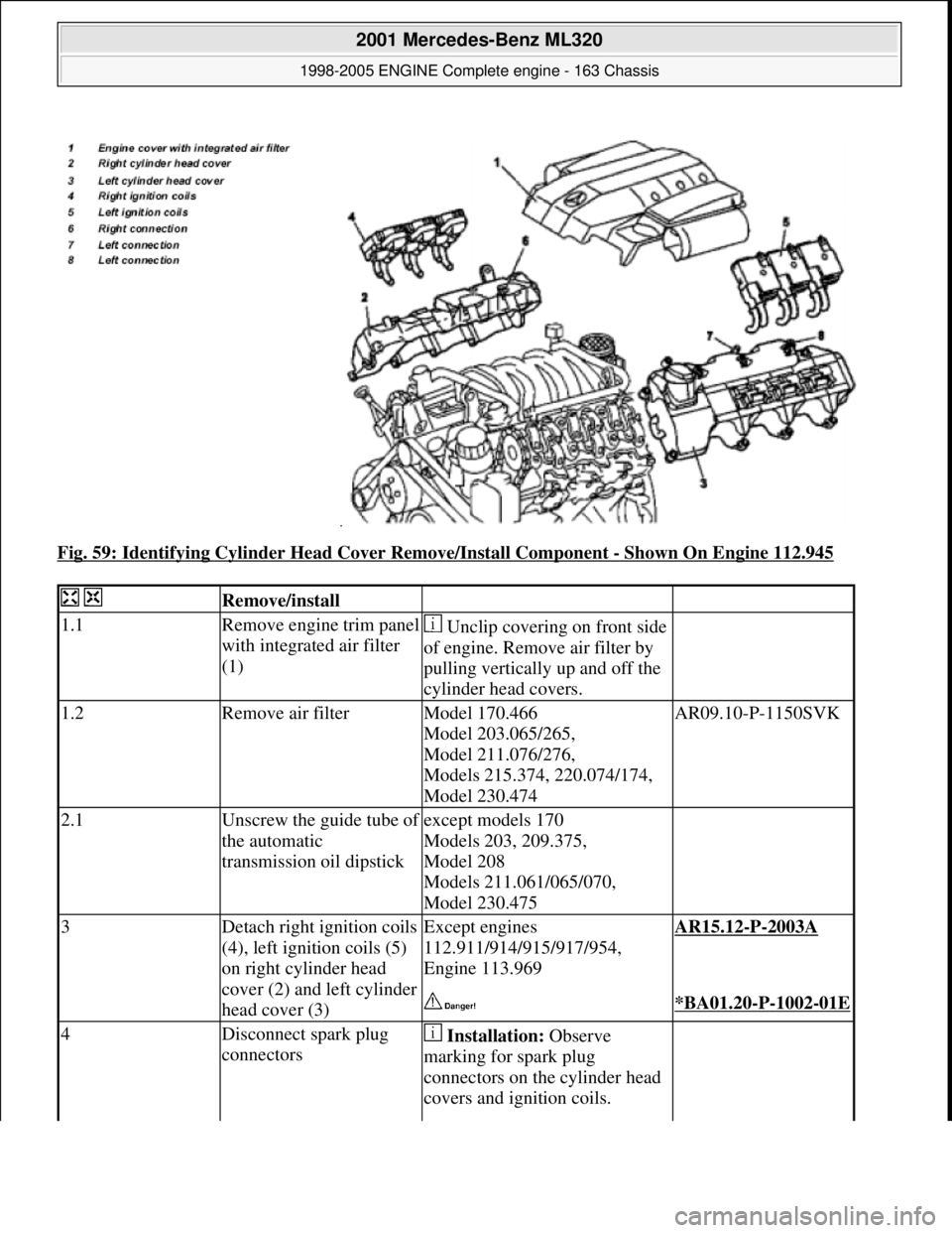
Fig. 59: Identifying Cylinder Head Cover Remove/Install Component - Shown On Engine 112.945
Remove/install
1.1Remove engine trim panel
with integrated air filter
(1) Unclip covering on front side
of engine. Remove air filter by
pulling vertically up and off the
cylinder head covers.
1.2Remove air filterModel 170.466
Model 203.065/265,
Model 211.076/276,
Models 215.374, 220.074/174,
Model 230.474AR09.10-P-1150SVK
2.1Unscrew the guide tube of
the automatic
transmission oil dipstickexcept models 170
Models 203, 209.375,
Model 208
Models 211.061/065/070,
Model 230.475
3Detach right ignition coils
(4), left ignition coils (5)
on right cylinder head
cover (2) and left cylinder
head cover (3)Except engines
112.911/914/915/917/954,
Engine 113.969AR15.12-P-2003A
*BA01.20-P-1002-01E
4Disconnect spark plug
connectors Installation: Observe
marking for spark plug
connectors on the cylinder head
covers and ignition coils.
2001 Mercedes-Benz ML320
1998-2005 ENGINE Complete engine - 163 Chassis
me
Saturday, October 02, 2010 3:17:56 PMPage 67 © 2006 Mitchell Repair Information Company, LLC.
Page 2444 of 4133
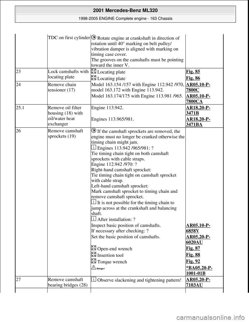
TDC on first cylinder Rotate engine at cra nkshaft in direction of
rotation until 40° marking on belt pulley/
vibration damper is al igned with marking on
timing case cover.
The grooves on the camshafts must be pointing
toward the inner V.
23Lock camshafts with
locating plate Locating plateFig. 85
Locating plateFig. 86
24Remove chain
tensioner (17)Model 163.154 /157 with Engine 112.942 /970,
model 163.172 with Engine 113.942.AR05.10-P-
7800C
Model 163.174/175 with Engine 113.981 /965.AR05.10-P-
7800CA
25.1Remove oil filter
housing (18) with
oil/water heat
exchangerEngine 113.942.AR18.20-P-
3471B
Engines 113.965/981.AR18.20-P-
3471BA
26Remove camshaft
sprockets (19) If the camshaft sprockets are removed, the
engine must no longer be cranked otherwise the
timing chain might jam.
Engines 113.942 /965/981: ?
Tie timing chain tight on both camshaft
sprockets with cable straps.
Engine 112.942 /970: ?
Right-hand camshaft sprocket:
Tie timing chain tight on camshaft sprocket
with cable strap.
Left-hand camshaft sprocket:
Mark camshaft sprocket to timing chain and
remove camshaft sprocket.
It is not possible for the timing chain to
jump across at the crankshaft and balancing
shaft.
After installation: ?
Inspect basic positi on of camshafts.
If necessary after checking: ?AR05.10-P-
6858V
Set the basic position of camshafts.AR05.20-P-
6020AU
Open-end wrenchFig. 87
Insertion toolFig. 88
Torque wrenchFig. 92
*BA05.20-P-
1001-01B
27Remove camshaft
bearing bridges (28) Observe slackening and tightening pattern!AR05.20-P-
7103AU
2001 Mercedes-Benz ML320
1998-2005 ENGINE Complete engine - 163 Chassis
me
Saturday, October 02, 2010 3:17:57 PMPage 88 © 2006 Mitchell Repair Information Company, LLC.
Page 2456 of 4133
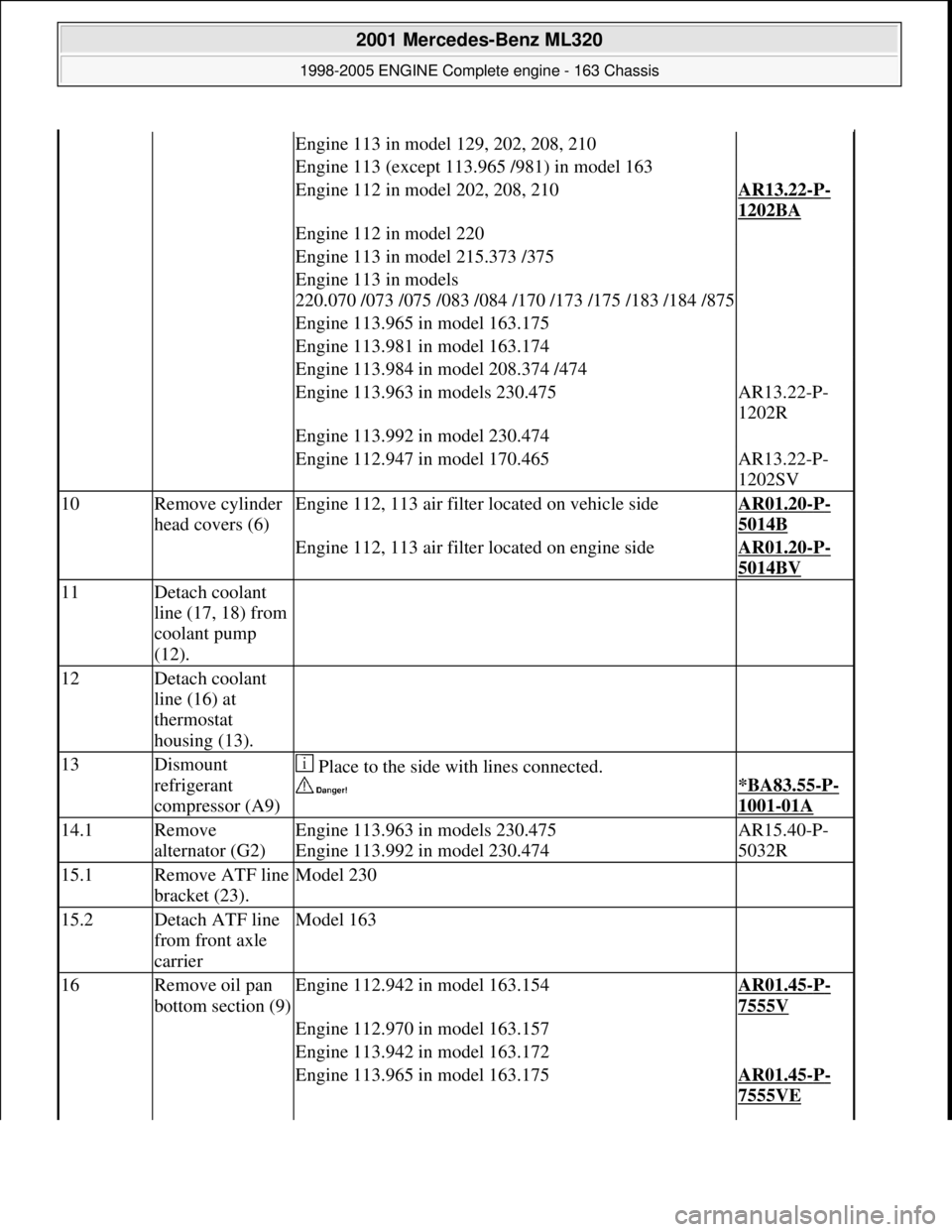
Engine 113 in model 129, 202, 208, 210
Engine 113 (except 113.965 /981) in model 163
Engine 112 in model 202, 208, 210AR13.22-P-
1202BA
Engine 112 in model 220
Engine 113 in model 215.373 /375
Engine 113 in models
220.070 /073 /075 /083 /084 /170 /173 /175 /183 /184 /875
Engine 113.965 in model 163.175
Engine 113.981 in model 163.174
Engine 113.984 in model 208.374 /474
Engine 113.963 in models 230.475AR13.22-P-
1202R
Engine 113.992 in model 230.474
Engine 112.947 in model 170.465AR13.22-P-
1202SV
10Remove cylinder
head covers (6)Engine 112, 113 air filter located on vehicle sideAR01.20-P-
5014B
Engine 112, 113 air filter located on engine sideAR01.20-P-
5014BV
11Detach coolant
line (17, 18) from
coolant pump
(12).
12Detach coolant
line (16) at
thermostat
housing (13).
13Dismount
refrigerant
compressor (A9) Place to the side with lines connected.
*BA83.55-P-
1001-01A
14.1Remove
alternator (G2)Engine 113.963 in models 230.475
Engine 113.992 in model 230.474AR15.40-P-
5032R
15.1Remove ATF line
bracket (23).Model 230
15.2Detach ATF line
from front axle
carrierModel 163
16Remove oil pan
bottom section (9)Engine 112.942 in model 163.154AR01.45-P-
7555V
Engine 112.970 in model 163.157
Engine 113.942 in model 163.172
Engine 113.965 in model 163.175AR01.45-P-
7555VE
2001 Mercedes-Benz ML320
1998-2005 ENGINE Complete engine - 163 Chassis
me
Saturday, October 02, 2010 3:17:57 PMPage 100 © 2006 Mitchell Repair Information Company, LLC.
Page 2458 of 4133
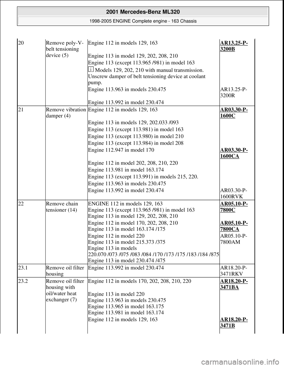
20Remove poly-V-
belt tensioning
device (5)Engine 112 in models 129, 163AR13.25-P-
3200B
Engine 113 in model 129, 202, 208, 210
Engine 113 (except 113.965 /981) in model 163
Models 129, 202, 210 with manual transmission.
Unscrew damper of belt te nsioning device at coolant
pump.
Engine 113.963 in models 230.475AR13.25-P-
3200R
Engine 113.992 in model 230.474
21Remove vibration
damper (4)Engine 112 in models 129, 163AR03.30-P-
1600C
Engine 113 in models 129, 202.033 /093
Engine 113 (except 113.981) in model 163
Engine 113 (except 113.980) in model 210
Engine 113 (except 113.984) in model 208
Engine 112.947 in model 170AR03.30-P-
1600CA
Engine 112 in model 202, 208, 210, 220
Engine 113.981 in model 163.174
Engine 113 (except 113.991) in models 215, 220.
Engine 113.963 in models 230.475
Engine 113.992 in model 230.474AR03.30-P-
1600RVK
22Remove chain
tensioner (14)ENGINE 112 in models 129, 163
Engine 113 (except 113.965 /981) in model 163
Engine 113 in model 129, 202, 208, 210AR05.10-P-
7800C
Engine 112 in model 170, 202, 208, 210
Engine 113 in model 163.174 /175AR05.10-P-
7800CA
Engine 112 in model 220
Engine 113 in model 215.373 /375
Engine 113 in models
220.070 /073 /075 /083 /084 /170 /173 /175 /183 /184 /875
Engine 113 in model 230.474 /475AR05.10-P-
7800AM
23.1Remove oil filter
housingEngine 113.992 in model 230.474AR18.20-P-
3471RKV
23.2Remove oil filter
housing with
oil/water heat
exchanger (7)Engine 112 in models 170, 202, 208, 210, 220AR18.20-P-
3471BA
Engine 113 in model 220
Engine 113.963 in models 230.475
Engine 113.965 in model 163.175
Engine 113.981 in model 163.174
Engine 112 in models 129, 163AR18.20-P-
3471B
2001 Mercedes-Benz ML320
1998-2005 ENGINE Complete engine - 163 Chassis
me
Saturday, October 02, 2010 3:17:57 PMPage 102 © 2006 Mitchell Repair Information Company, LLC.
Page 2475 of 4133
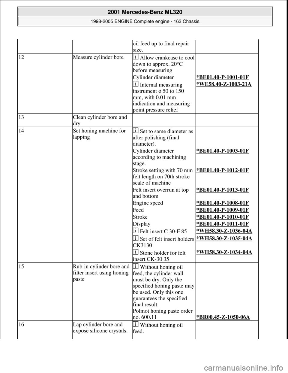
oil feed up to final repair
size.
12Measure cylinder boreAllow crankcase to cool
down to approx. 20°C
before measuring
Cylinder diameter*BE01.40-P-1001-01F
Internal measuring
instrument ø 50 to 150
mm, with 0.01 mm
indication and measuring
point pressure relief*WE58.40-Z-1003-21A
13Clean cylinder bore and
dry
14Set honing machine for
lapping Set to same diameter as
after polishing (final
diameter).
Cylinder diameter
according to machining
stage.*BE01.40-P-1003-01F
Stroke setting with 70 mm
felt length on 70th stroke
scale of machine*BE01.40-P-1012-01F
Felt insert overrun at top
and bottom*BE01.40-P-1013-01F
Engine speed*BE01.40-P-1008-01F
Feed*BE01.40-P-1009-01F
Stroke*BE01.40-P-1010-01F
Display*BE01.40-P-1011-01F
Felt insert C 30-F 85*WH58.30-Z-1036-04A
Set of felt insert holders
CK3130*WH58.30-Z-1035-04A
Stone holder for felt
insert CK-30 35*WH58.30-Z-1034-04A
15Rub-in cylinder bore and
filter insert using honing
paste Without honing oil
feed, the cylinder wall
must be dry. Only the
specified honing paste may
be used. Only this one
guarantees the specified
final result.
Polmot honing paste order
no. 600.11
*BR00.45-Z-1050-06A
16Lap cylinder bore and
expose silicone crystals. Without honing oil
feed.
2001 Mercedes-Benz ML320
1998-2005 ENGINE Complete engine - 163 Chassis
me
Saturday, October 02, 2010 3:17:57 PMPage 119 © 2006 Mitchell Repair Information Company, LLC.
Page 2476 of 4133
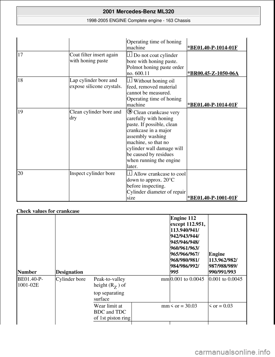
Check values for crankcase
Operating time of honing
machine
*BE01.40-P-1014-01F
17Coat filter insert again
with honing paste Do not coat cylinder
bore with honing paste.
Polmot honing paste order
no. 600.11
*BR00.45-Z-1050-06A
18Lap cylinder bore and
expose silicone crystals. Without honing oil
feed, removed material
cannot be measured.
Operating time of honing
machine
*BE01.40-P-1014-01F
19Clean cylinder bore and
dry Clean crankcase very
carefully with honing
paste. If possible, clean
crankcase in a major
assembly washing
machine, so that no
cylinder wall damage will
be caused by residues
when running the engine
later.
20Inspect cylinder boreAllow crankcase to cool
down to approx. 20°C
before inspecting.
Cylinder diameter of repair
size
*BE01.40-P-1001-01F
NumberDesignation
Engine 112
except 112.951,
113.940/941/
942/943/944/
945/946/948/
960/961/963/
965/966/967/
968/980/981/
984/986/992/
995
Engine
113.962/982/
987/988/989/
990/991/993
BE01.40-P-
1001-02E Cylinder borePeak-to-valley
height (R
Z ) of
top separating
surface
mm0.001 to 0.00450.001 to 0.0045
Wear limit at
BDC and TDC
of 1st piston ringmm< or = 30.03< or = 0.03
2001 Mercedes-Benz ML320
1998-2005 ENGINE Complete engine - 163 Chassis
me
Saturday, October 02, 2010 3:17:57 PMPage 120 © 2006 Mitchell Repair Information Company, LLC.
Page 2492 of 4133
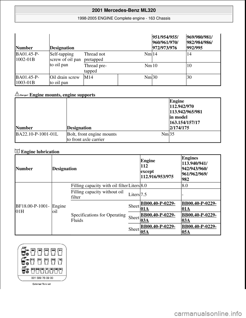
Engine mounts, engine supports
Engine lubrication
NumberDesignation
951/954/955/
960/961/970/
972/973/976969/980/981/
982/984/986/
992/995
BA01.45-P-
1002-01BSelf-tapping
screw of oil pan
to oil panThread not
pretappedNm1414
Thread pre-
tappedNm1010
BA01.45-P-
1003-01BOil drain screw
to oil panM14Nm3030
NumberDesignation
Engine
112.942/970
113.942/965/981
in model
163.154/157/17
2/174/175
BA22.10-P-1001-01LBolt, front engine mounts
to front axle carrierNm35
NumberDesignation
Engine
112
except
112.916/953/975Engines
113.940/941/
942/943/960/
961/962/969/
982
BF18.00-P-1001-
01HEngine
oil
Filling capacity with oil filterLiters8.08.0
Filling capacity without oil
filterLiters7.5-
Specifications for Operating
Fluids
SheetBB00.40-P-0229-
01A
BB00.40-P-0229-
01A
SheetBB00.40-P-0229-
03A
BB00.40-P-0229-
03A
SheetBB00.40-P-0229-
05A
BB00.40-P-0229-
05A
2001 Mercedes-Benz ML320
1998-2005 ENGINE Complete engine - 163 Chassis
me
Saturday, October 02, 2010 3:17:58 PMPage 136 © 2006 Mitchell Repair Information Company, LLC.
Page 2495 of 4133
Engine mounts, engine supports
Engine lubrication
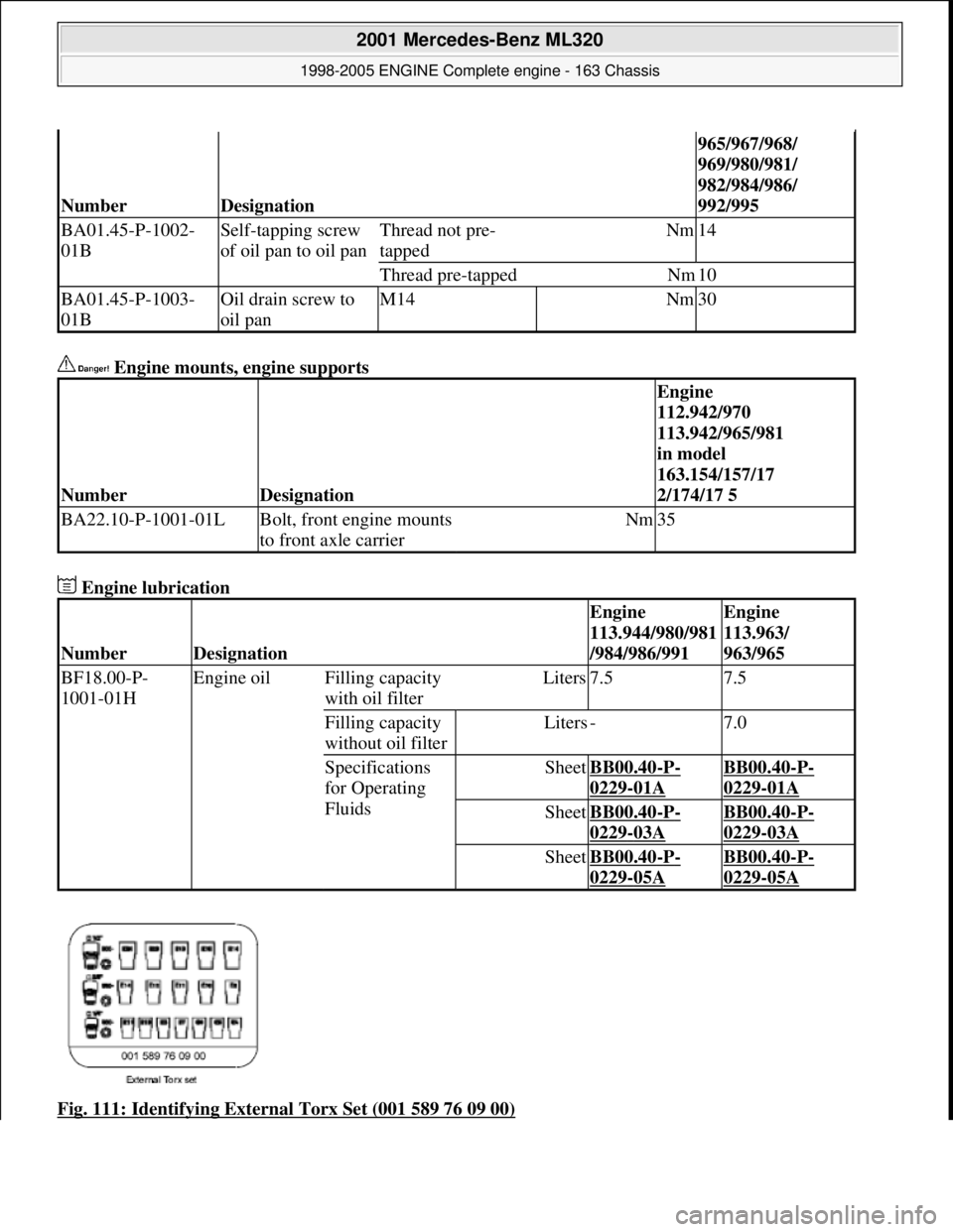
Fig. 111: Identifying External Torx Set (001 589 76 09 00)
NumberDesignation
965/967/968/
969/980/981/
982/984/986/
992/995
BA01.45-P-1002-
01BSelf-tapping screw
of oil pan to oil panThread not pre-
tappedNm14
Thread pre-tappedNm10
BA01.45-P-1003-
01BOil drain screw to
oil panM14Nm30
NumberDesignation
Engine
112.942/970
113.942/965/981
in model
163.154/157/17
2/174/17 5
BA22.10-P-1001-01LBolt, front engine mounts
to front axle carrierNm35
NumberDesignation
Engine
113.944/980/981
/984/986/991Engine
113.963/
963/965
BF18.00-P-
1001-01HEngine oilFilling capacity
with oil filterLiters7.57.5
Filling capacity
without oil filterLiters-7.0
Specifications
for Operating
FluidsSheetBB00.40-P-
0229-01A
BB00.40-P-
0229-01A
SheetBB00.40-P-
0229-03A
BB00.40-P-
0229-03A
SheetBB00.40-P-
0229-05A
BB00.40-P-
0229-05A
2001 Mercedes-Benz ML320
1998-2005 ENGINE Complete engine - 163 Chassis
me
Saturday, October 02, 2010 3:17:58 PMPage 139 © 2006 Mitchell Repair Information Company, LLC.
Page 2589 of 4133
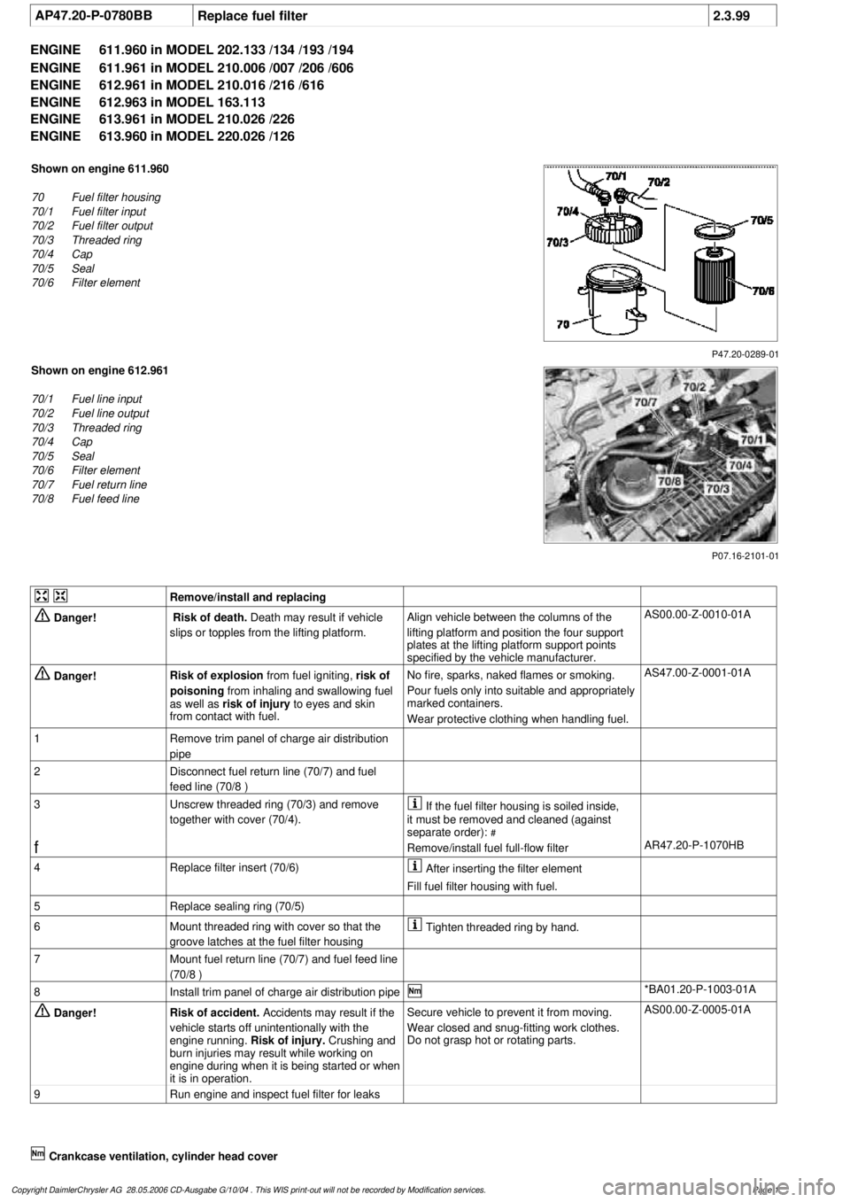
AP47.20-P-0780BB
Replace fuel filter
2.3.99
ENGINE
611.960 in MODEL 202.133 /134 /193 /194
ENGINE
611.961 in MODEL 210.006 /007 /206 /606
ENGINE
612.961 in MODEL 210.016 /216 /616
ENGINE
612.963 in MODEL 163.113
ENGINE
613.961 in MODEL 210.026 /226
ENGINE
613.960 in MODEL 220.026 /126
P47.20-0289-01
Shown on engine 611.960
70
Fuel filter housing
70/1
Fuel filter input
70/2
Fuel filter output
70/3
Threaded ring
70/4
Cap
70/5
Seal
70/6
Filter element
P07.16-2101-01
Shown on engine 612.961
70/1
Fuel line input
70/2
Fuel line output
70/3
Threaded ring
70/4
Cap
70/5
Seal
70/6
Filter element
70/7
Fuel return line
70/8
Fuel feed line
Remove/install and replacing
Danger!
Risk of death.
Death may result if vehicle
slips or topples from the lifting platform.
Align vehicle between the columns of the
lifting platform and position the four support
plates
at the lifting platform support points
specified by the vehicle manufacturer.
AS00.00-Z-0010-01A
Danger!
Risk of explosion
from fuel igniting,
risk of
poisoning
from inhaling and swallowing fuel
as well as
risk of injury
to eyes and skin
from contact with fuel.
No fire, sparks, naked flames or smoking.
Pour fuels only into suitable and appropriately
marked containers.
Wear protective clothing when handling fuel.
AS47.00-Z-0001-01A
1
Remove trim panel of charge air distribution
pipe
2
Disconnect fuel return line (70/7) and fuel
feed line (70/8 )
3
Unscrew threaded ring (70/3) and remove
together with cover (70/4).
If the fuel filter housing is soiled inside,
it must be removed and cleaned (against
separate order):
#
f
Remove/install fuel full-flow filter
AR47.20-P-1070HB
4
Replace filter insert (70/6)
After inserting the filter element
Fill fuel filter housing with fuel.
5
Replace sealing ring (70/5)
6
Mount threaded ring with cover so that the
groove latches at the fuel filter housing
Tighten threaded ring by hand.
7
Mount fuel return line (70/7) and fuel feed line
(70/8 )
8
Install trim panel of charge air distribution pipe
*BA01.20-P-1003-01A
Danger!
Risk of accident.
Accidents may result if the
vehicle starts off unintentionally with the
engine running.
Risk of injury.
Crushing and
burn injuries may result while working on
engine during when it is being started or when
it is in operation.
Secure vehicle to prevent it from moving.
Wear closed and snug-fitting work clothes.
Do not grasp hot or rotating parts.
AS00.00-Z-0005-01A
9
Run engine and inspect fuel filter for leaks
Crankcase ventilation, cylinder head cover
Copyright DaimlerChrysler AG 28.05.2006 CD-Ausgabe G/10/04 . This WIS print-out will not be recorde
d by Modification services.
Page 1