wheel bolts MERCEDES-BENZ ML320 1997 Complete Owner's Guide
[x] Cancel search | Manufacturer: MERCEDES-BENZ, Model Year: 1997, Model line: ML320, Model: MERCEDES-BENZ ML320 1997Pages: 4133, PDF Size: 88.89 MB
Page 2551 of 4133
Wheel location, hub
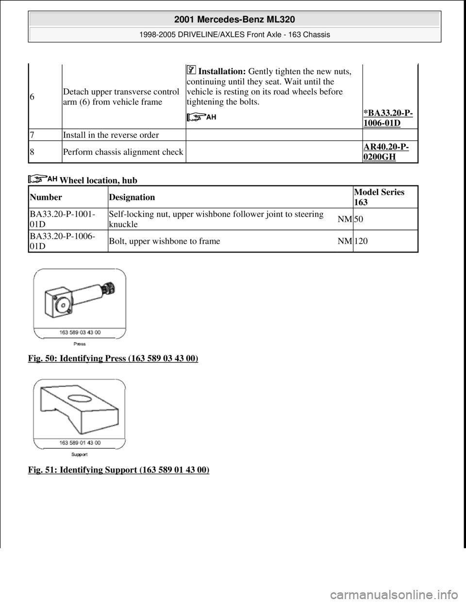
Fig. 50: Identifying Press (163 589 03 43 00)
Fig. 51: Identifying Support (163 589 01 43 00)
6Detach upper transverse control
arm (6) from vehicle frame
Installation: Gently tighten the new nuts,
continuing until they seat. Wait until the
vehicle is resting on it s road wheels before
tightening the bolts.
*BA33.20-P-
1006-01D
7Install in the reverse order
8Perform chassis alignment check AR40.20-P-
0200GH
NumberDesignationModel Series
163
BA33.20-P-1001-
01DSelf-locking nut, upper wishbone follower joint to steering
knuckleNM50
BA33.20-P-1006-
01DBolt, upper wishbone to frameNM120
2001 Mercedes-Benz ML320
1998-2005 DRIVELINE/AXLES Front Axle - 163 Chassis
me
Saturday, October 02, 2010 3:38:22 PMPage 32 © 2006 Mitchell Repair Information Company, LLC.
Page 2555 of 4133
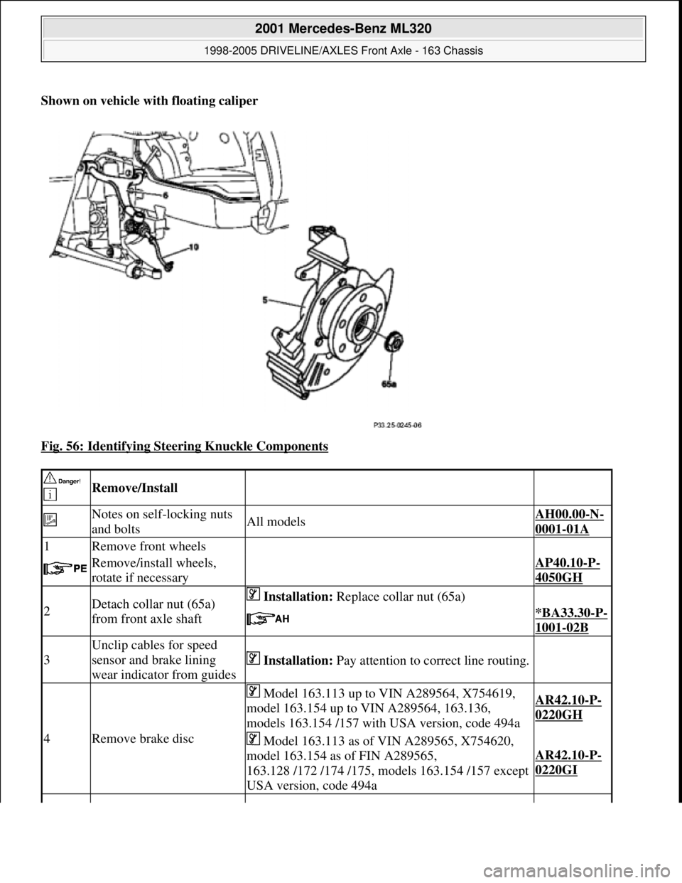
Shown on vehicle with floating caliper
Fig. 56: Identifying Steering Knuckle Components
Remove/Install
Notes on self-locking nuts
and boltsAll modelsAH00.00-N-
0001-01A
1Remove front wheels
Remove/install wheels,
rotate if necessaryAP40.10-P-
4050GH
2Detach collar nut (65a)
from front axle shaft Installation: Replace collar nut (65a)
*BA33.30-P-
1001-02B
3
Unclip cables for speed
sensor and brake lining
wear indicator from guides
Installation: Pay attention to correct line routing.
4Remove brake disc
Model 163.113 up to VIN A289564, X754619,
model 163.154 up to VIN A289564, 163.136,
models 163.154 /157 with USA version, code 494aAR42.10-P-
0220GH
Model 163.113 as of VIN A289565, X754620,
model 163.154 as of FIN A289565,
163.128 /172 /174 /175, models 163.154 /157 except
USA version, code 494a
AR42.10-P-
0220GI
2001 Mercedes-Benz ML320
1998-2005 DRIVELINE/AXLES Front Axle - 163 Chassis
me
Saturday, October 02, 2010 3:38:22 PMPage 36 © 2006 Mitchell Repair Information Company, LLC.
Page 2562 of 4133
Wheel location, hub
Front final-drive unit
Propeller shaft of front axle gear
Front axle gear
Thrust pieceFig. 45
SupportFig. 46
PressFig. 47
5Remove lower engine compartment
panelingModel 163.157 /172 /174 /175AR61.20-P-
1105GH
Model 163.113 /128AR94.30-P-
5400GH
6Press left and right front axle shafts out
of front axle gear Do not damage shield.
Suspend steering knuckle with
wire.
7Disconnect vent hose from front axle
gear
8Remove bolts (14a) *BA33.30-P-
1001-03B
9Remove front axle gear (14).
10Install in the reverse order
NumberDesignationModel 163
BA33.20-P-1001-01DSelf-locking nut, upper wishbone follower joint to steering knuckleNm50
NumberDesignationModel 163
BA33.30-P-1001-03BBolt securing front axle gear to front axle carrierNm135
BA33.30-P-1002-03BOil filler screw, front axle gearNm50
BA33.30-P-1003-03BOil drain screw, front axle gearNm50
NumberDesignationModel 163
BA41.20-P-1001-01ASelf-locking bolt of propeller shaft to front-axle gear flangeNm40
Number Designation Model 163
BF33.30-P-1001-
03BFilling capacityFront axle gearLiters1.2
Specifications for Operating
FluidsSheetBB00.40-P-0235-
07B
2001 Mercedes-Benz ML320
1998-2005 DRIVELINE/AXLES Front Axle - 163 Chassis
me
Saturday, October 02, 2010 3:38:22 PMPage 43 © 2006 Mitchell Repair Information Company, LLC.
Page 2567 of 4133
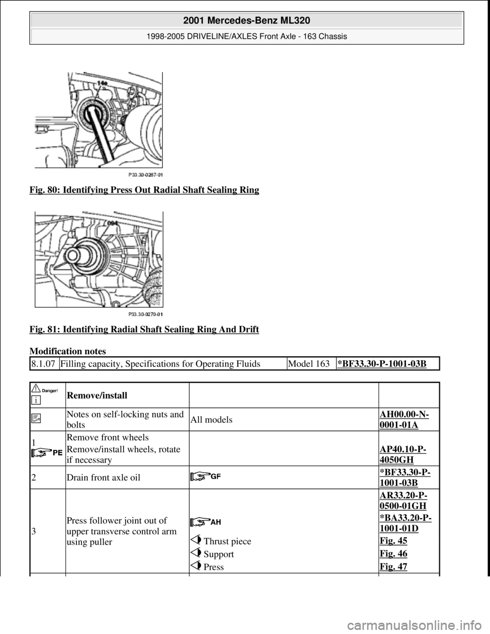
Fig. 80: Identifying Press Ou t Radial Shaft Sealing Ring
Fig. 81: Identifying Radial Sh aft Sealing Ring And Drift
Modification notes
8.1.07Filling capacity, Specificat ions for Operating FluidsModel 163*BF33.30-P-1001-03B
Remove/install
Notes on self-locking nuts and
boltsAll modelsAH00.00-N-
0001-01A
1
Remove front wheels
Remove/install wheels, rotate
if necessaryAP40.10-P-
4050GH
2Drain front axle oil *BF33.30-P-
1001-03B
3
Press follower joint out of
upper transverse control arm
using puller
AR33.20-P-
0500-01GH
*BA33.20-P-
1001-01D
Thrust pieceFig. 45
SupportFig. 46
PressFig. 47
2001 Mercedes-Benz ML320
1998-2005 DRIVELINE/AXLES Front Axle - 163 Chassis
me
Saturday, October 02, 2010 3:38:22 PMPage 48 © 2006 Mitchell Repair Information Company, LLC.
Page 2570 of 4133
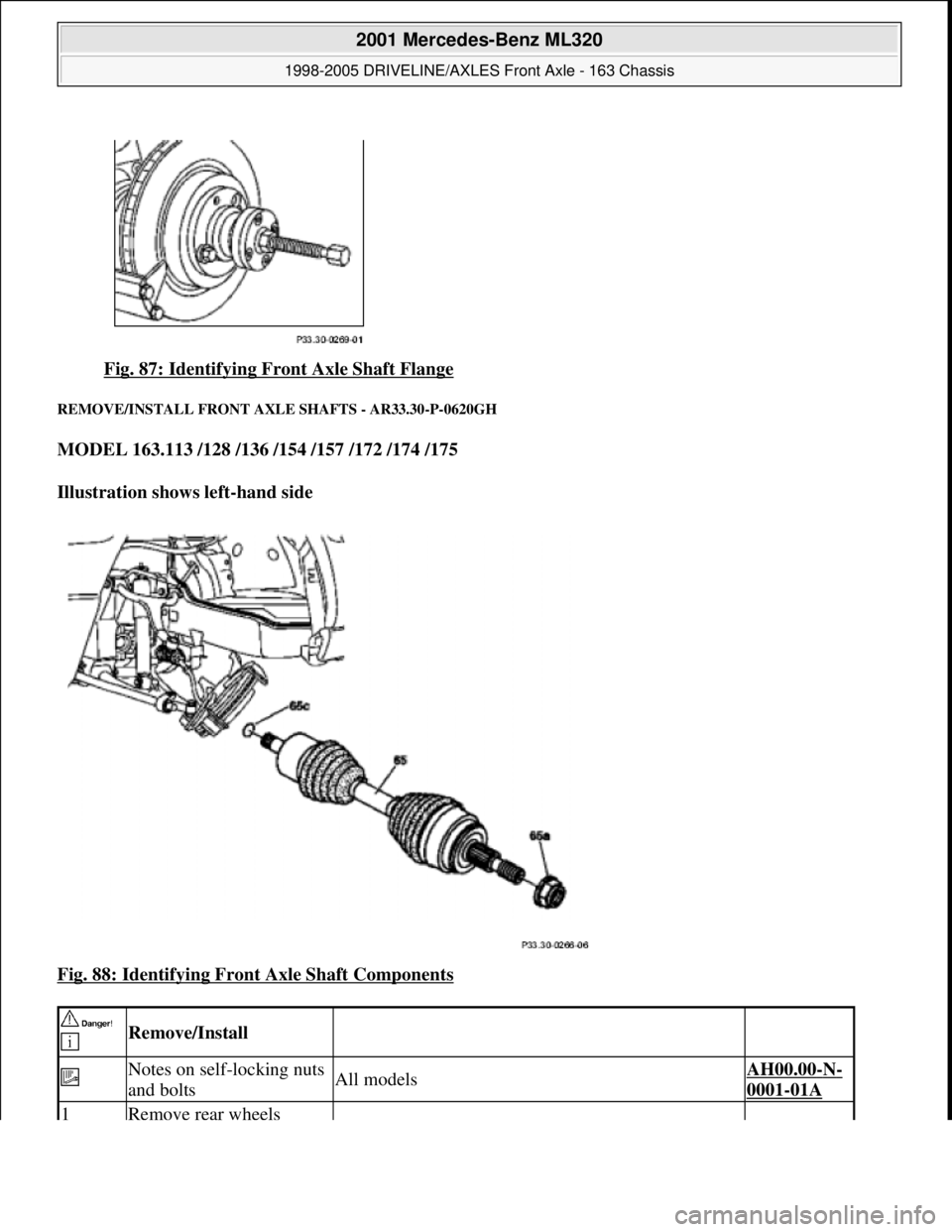
Fig. 87: Identifying Front Axle Shaft Flange
REMOVE/INSTALL FRON T AXLE SHAFTS - AR33.30-P-0620GH
MODEL 163.113 /128 /136 /154 /157 /172 /174 /175
Illustration shows left-hand side
Fig. 88: Identifying Front Axle Shaft Components
Remove/Install
Notes on self-locking nuts
and boltsAll modelsAH00.00-N-
0001-01A
1Remove rear wheels
2001 Mercedes-Benz ML320
1998-2005 DRIVELINE/AXLES Front Axle - 163 Chassis
me
Saturday, October 02, 2010 3:38:22 PMPage 51 © 2006 Mitchell Repair Information Company, LLC.
Page 2609 of 4133

Remove, Install
Danger!
Risk of explosion
from fuel igniting,
risk of
poisoning
from inhaling and swallowing fuel
as well as
risk of injury
to eyes and skin
from contact with fuel.
Fire, sparks, open flames or smoking
forbidden.
Pour fuels only into suitable and appropriately
marked containers.
Wear protective clothing when handling fuel.
AS47.00-Z-0001-01A
1
Drain fuel tank
Via fuel pump. NOT for model 163.113/128.
AR47.10-P-4001GH
If fuel pump faulty, and model 163.113/128.
AR47.10-P-4000GH
*BF47.10-P-1001-01A
2
Unscrew filler cap (2) and detach from filler
cap attachment (4)
3.1
Remove left seat of 3rd seat row
If installed. See owner's manual
4
Unclip cover of left-hand side panel (1)
5.1
Detach fuel lines of expansion reservoir and
separate from filler neck
As of VIN A289565. NOT for model
163.113/128.
6
Detach fuel filler neck from guide funnel
Installation:
Check O-ring and replace if
necessary. Ensure that the bayonet-lock
remains above
the pressure sensor.
Ensure it is correctly located when installed.
Open bayonet lock (3) to do this.
7
Pull filler neck through toward interior
Screw on cap again in order to avoid fuel
flowing out.
8.1
Remove fuel tank pressure sensor (B4/3)
Only USA version
AR47.10-P-8022GH
9.1
Detach bolted connection of fuel tank filler
neck/ground (X36/4) from filler neck
NOT for model 163.113/128.
10.1
Cut cable strap for retaining clips of fuel lines
at filler neck and remove retaining clips
As of VIN A289565. NOT for model
163.113/128.
Danger!
Risk of fatal accident
from vehicle slipping
or toppling off the lift platform
Align vehicle between the columns of lifting
platform and position the four support plates
below the support strongpoints specified by
the vehicle manufacturer.
AS00.00-Z-0010-01A
11
Place the vehicle on lifting platform
AR00.60-P-1000GH
12
Separate rubber seal (5) from underside of
vehicle and remove filler neck from interior
Do not damage fuel lines at filler neck.
13
Remove left rear wheel
e
Removing and installing wheels, rotating if
necessary
AP40.10-P-4050GH
14
Remove spare wheel and spare wheel carrier
complete
NOT in the case of spare wheel
holder/spare wheel, code 849.
15
Cut a large safety cable strap for filler neck at
bracket on longitudinal frame member
16
Remove bracket from longitudinal frame
member
17
Disconnect connection for regeneration (77/2)
and fresh air connection (77/4) on activated
charcoal canister (77)
Installation
: Connect up lines as per
connection diagram:
#
Engine 111
AR47.30-P-8212-01GJ
Engines 112, 113
AR47.30-P-8212-01GI
Engines 112, 113 version
I
AR47.30-P-8212-01GH
Charcoal canister and fuel tank form a
single unit.
NOT for model 163.113/128.
18
Detach vent hose
At rear differential to rear of activated
charcoal reservoir.
19
Remove rear exhaust system heat shield.
Do not damage boot at rear axle shaft.
20
Disconnect rear propeller shaft at differential
Installation:
Install new self-locking bolts.
Tie up propeller shaft e.g. using welding
wire
Heat bolts with hot air fan to facilitate
removing. Mark propeller shaft and differential
gear flange for correct installed position.
*BA41.10-P-1002-01C
Copyright DaimlerChrysler AG 28.05.2006 CD-Ausgabe G/10/04 . This WIS print-out will not be recorde
d by Modification services.
Page 2
Page 3232 of 4133
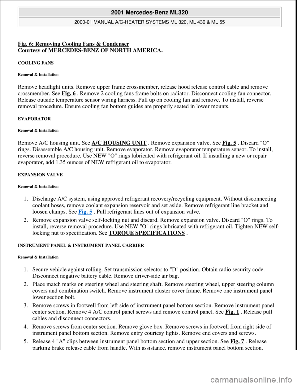
Fig. 6: Removing Cooling Fans & Condenser
Courtesy of MERCEDES-BENZ OF NORTH AMERICA.
COOLING FANS
Removal & Installation
Remove headlight units. Remove upper frame crossmember, release hood release control cable and remove
crossmember. See Fig. 6
. Remove 2 cooling fans frame bolts on radiator. Disconnect cooling fan connector.
Release outside temperature sensor wiring harness. Pull up on cooling fan and remove. To install, reverse
removal procedure. Ensure cooling fan bottom guides are properly seated in lower mounts.
EVAPORATOR
Removal & Installation
Remove A/C housing unit. See A/C HOUSING UNIT . Remove expansion valve. See Fig. 5 . Discard "O"
rings. Disassemble A/C housing unit. Remove evaporator. Remove evaporator temperature sensor. To install,
reverse removal procedure. Use NEW "O" rings lubricated with refrigerant oil. If installing a new or repair
evaporator, add 1.35 ounces of NEW refrigerant oil to evaporator.
EXPANSION VALVE
Removal & Installation
1. Discharge A/C system, using approved refrigerant recovery/recycling equipment. Without disconnecting
coolant hoses, remove coolant expansion reservoir and set aside. Remove refrigerant line bracket and
loosen clamps. See Fig. 5
. Pull refrigerant lines out of expansion valve.
2. Remove expansion valve self-locking nut and discard. Remove expansion valve. Discard "O" rings. To
install, reverse removal procedure. Use NEW "O" rings lubricated with refrigerant oil. Tighten NEW self-
locking nut to specification. See TORQUE SPECIFICATIONS
.
INSTRUMENT PANEL & INSTRUMENT PANEL CARRIER
Removal & Installation
1. Secure vehicle against rolling. Set transmission selector to "D" position. Obtain radio security code.
Disconnect negative battery cable. Remove driver-side air bag.
2. Place match marks on steering wheel and steering shaft. Remove steering wheel, upper steering column
covers and combination switch. Remove instrument cluster cover frame. Remove one instrument panel
lower section bolt.
3. Remove screws in footwell from left side of instrument panel bottom section. Remove instrument panel
center section. Remove 4 A/C control panel screws and remove control panel. See Fig. 1
. Release pull
cables and disconnect connectors.
4. Remove screws from center section. Remove glove box. Remove screws in footwell from right side of
instrument panel bottom section. Remove entry courtesy lights. Remove end covers and screws.
5. Release 4 "A" clips between instrument panel bottom section and upper section. See Fig. 7
. Release
parkin
g brake release cable from handle. With assistance, remove instrument panel bottom section.
2001 Mercedes-Benz ML320
2000-01 MANUAL A/C-HEATER SYSTEMS ML 320, ML 430 & ML 55
me
Saturday, October 02, 2010 3:25:10 PMPage 21 © 2006 Mitchell Repair Information Company, LLC.
Page 3485 of 4133

Rims
D
When changing wheels, for instance, when replacing steel
wheels with light-alloy rims, ensure that the wheel bolts
required for the spare wheel are stored in a clearly visible
location.
D
Since December 1994 models 202 and 124 with special
equipment light alloy disk wheels, are supplied with a sheet
steel spare wheel instead of a light alloy spare wheel. The
necessary wheel bolts are included with the steel spare wheel.
D
Only use approved Mercedes-Benz rims of the same version.
D
Reinforced steel rims are identified by a sticker on the wheel
disc.
D
The wheel bolts on steel and light-alloy rims should always be
tightened to the specified tightening torque using a torque
wrench.
It is not necessary to retorque the lug bolts after approximately
100 to 500 km.
D
The seat for the tire bead must display no corrosion marks.
D
Before inserting a new rubber valve, clean the contact surfaces
on the disk wheel.
On sheet steel-disk wheel wheel trims must be fitted to support
the rubber valve.
Damaged or deformed rims must not be repaired.
Tire pressure monitor
D
Before replacing a tire, check the date of manufacturer of the
wheel sensor: wheel sensors which are more than 5 years old
must be replaced.
D
Use STAR DIAGNOSIS to read out the actual values of the tire
pressure monitor. Check the remaining life of the wheel sensor
battery, replace the wheel sensor if necessary.
Copyright DaimlerChrysler AG 06.07.2006 CD-Ausgabe G/10/04 . This WIS print-out will not be recorde
d by Modification services.
Page 2
Page 3752 of 4133
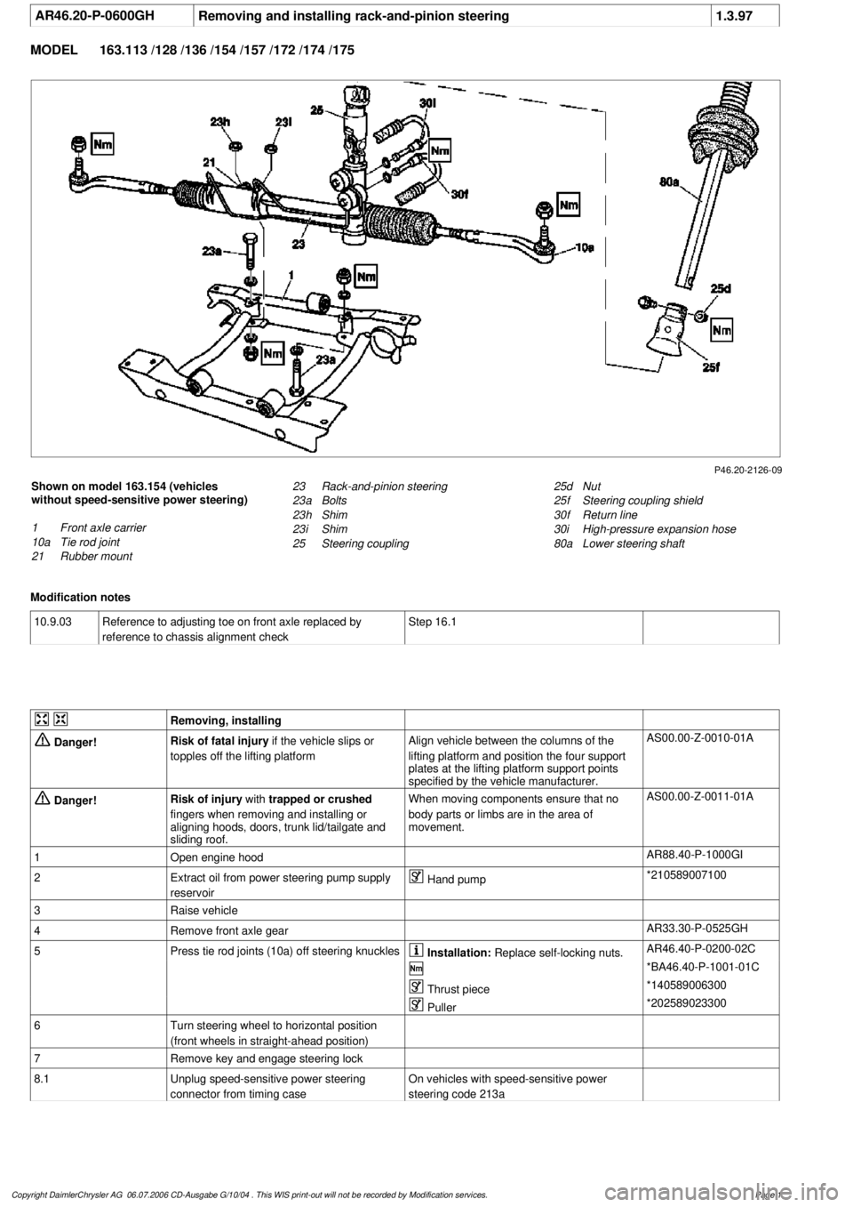
AR46.20-P-0600GH
Removing and installing rack-and-pinion steering
1.3.97
MODEL
163.113 /128 /136 /154 /157 /172 /174 /175
P46.20-2126-09
Shown on model 163.154 (vehicles
without speed-sensitive power steering)
1
Front axle carrier
10a
Tie rod joint
21
Rubber mount
25d
Nut
25f
Steering coupling shield
30f
Return line
30i
High-pressure expansion hose
80a
Lower steering shaft
23
Rack-and-pinion steering
23a
Bolts
23h
Shim
23i
Shim
25
Steering coupling
Modification notes
10.9.03
Reference to adjusting toe on front axle replaced by
reference to chassis alignment check
Step 16.1
Removing, installing
Danger!
Risk of fatal injury
if the vehicle slips or
topples off the lifting platform
Align vehicle between the columns of the
lifting platform and position the four support
plates
at the lifting platform support points
specified by the vehicle manufacturer.
AS00.00-Z-0010-01A
Danger!
Risk of injury
with
trapped or crushed
fingers when removing and installing or
aligning hoods, doors, trunk lid/tailgate and
sliding roof.
When moving components ensure that no
body parts or limbs are in the area of
movement.
AS00.00-Z-0011-01A
1
Open engine hood
AR88.40-P-1000GI
2
Extract oil from power steering pump supply
reservoir
Hand pump
*210589007100
3
Raise vehicle
4
Remove front axle gear
AR33.30-P-0525GH
5
Press tie rod joints (10a) off steering knuckles
Installation:
Replace self-locking nuts.
AR46.40-P-0200-02C
*BA46.40-P-1001-01C
Thrust piece
*140589006300
Puller
*202589023300
6
Turn steering wheel to horizontal position
(front wheels in straight-ahead position)
7
Remove key and engage steering lock
8.1
Unplug speed-sensitive power steering
connector from timing case
On vehicles with speed-sensitive power
steering code 213a
Copyright DaimlerChrysler AG 06.07.2006 CD-Ausgabe G/10/04 . This WIS print-out will not be recorde
d by Modification services.
Page 1
Page 3891 of 4133
Fig. 4: Connecting Hand Held Tester Scan Tool To OBD-II Data Link Connector
Courtesy of MERCEDES-BENZ OF NORTH AMERICA.
TESTING
Starter malfunctions may cause a Di agnostic Trouble Codes (DTCs) to be stored in Motor Electronics
Sequential Fuel Injection (ME-SFI) sy stem. After repairs are completed check for and erase any DTCs stored in
(ME-SFI) system. See appropriate SE LF-DIAGNOSTICS article in ENGINE PERFORMANCE. If cause of
starter malfunction is not engine pe rformance related, replace starter.
REMOVAL & INSTALLATION
STARTER
Removal & Installation
1. Disconnect and shield negative battery cable. See BATTERY DISCONNECT/CONNECT under
SERVICE PRECAUTIONS.
2. Remove nut (2) for inner fender. See Fig. 5
. Pull front and rear section of inner fender (1) downward.
Move inner fender away inward and downward. Pull toward outside over wheel. DO NOT damage fender
cutout or paint.
3. On vehicles with 112 engine, remove nut (6) at shield (5) of left engine mount and take out shield. See
Fig. 6
.
4. On all vehicles, disconnect circuit 30 (1) and circuit 50 (2) cables from starter. See Fig. 6
. Remove bolts
(3) for starter-to-crankcase. Take starter (M1) out to the side.
5. If replacing starter on vehicles with manual transmission, check ring gear at flywheel for wear and
damage. If replacing starter on vehicles with auto matic transmission, check ring gear on drive plate for
wear and damage. Repair or repl ace damaged parts as necessary.
6. To install, reverse removal proce dure. Replace bolts with locking splines, micro-encapsulated bolts and
self-locking nuts. Mating thread of mi cro-encapsulated bolts must be cleaned to remove all residue of old
bolt locking compound. Tighten fasteners to specification. See TORQUE SPECIFICATIONS
. Connect
battery. See BATTERY DISCONNECT/CONNECTunder SERVICE PRECAUTIONS.
NOTE: Numbers and letters in text refe
r to numbers and letters in figures.
2001 Mercedes-Benz ML320
2001-04 STARTING & CHARGING SYSTEMS Starters - 163 Chassis
me
Saturday, October 02, 2010 3:19:47 PMPage 9 © 2006 Mitchell Repair Information Company, LLC.