ECU MERCEDES-BENZ ML350 1997 Complete Repair Manual
[x] Cancel search | Manufacturer: MERCEDES-BENZ, Model Year: 1997, Model line: ML350, Model: MERCEDES-BENZ ML350 1997Pages: 4133, PDF Size: 88.89 MB
Page 2589 of 4133
AP47.20-P-0780BB
Replace fuel filter
2.3.99
ENGINE
611.960 in MODEL 202.133 /134 /193 /194
ENGINE
611.961 in MODEL 210.006 /007 /206 /606
ENGINE
612.961 in MODEL 210.016 /216 /616
ENGINE
612.963 in MODEL 163.113
ENGINE
613.961 in MODEL 210.026 /226
ENGINE
613.960 in MODEL 220.026 /126
P47.20-0289-01
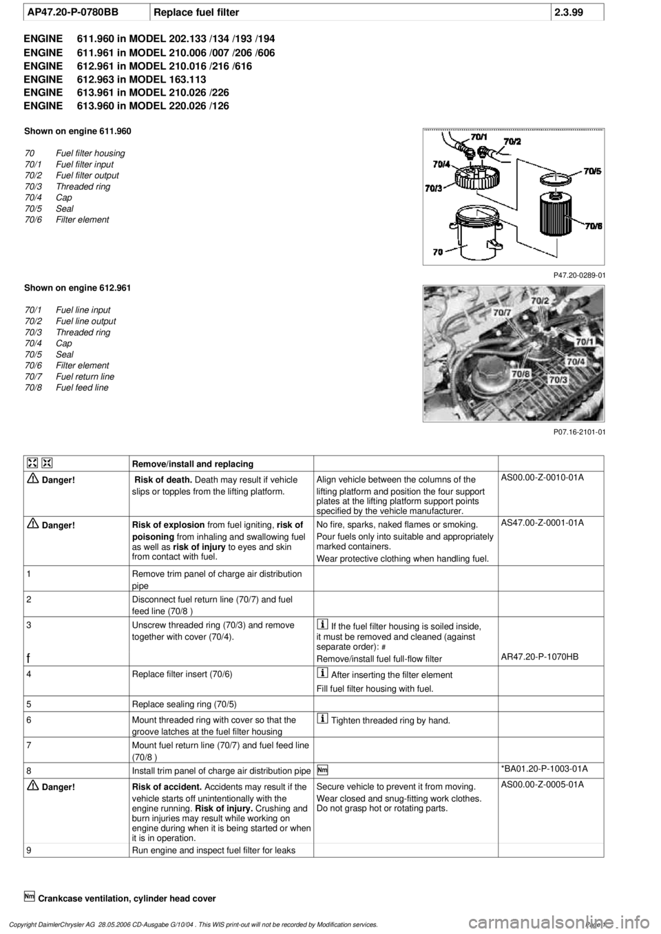
Shown on engine 611.960
70
Fuel filter housing
70/1
Fuel filter input
70/2
Fuel filter output
70/3
Threaded ring
70/4
Cap
70/5
Seal
70/6
Filter element
P07.16-2101-01
Shown on engine 612.961
70/1
Fuel line input
70/2
Fuel line output
70/3
Threaded ring
70/4
Cap
70/5
Seal
70/6
Filter element
70/7
Fuel return line
70/8
Fuel feed line
Remove/install and replacing
Danger!
Risk of death.
Death may result if vehicle
slips or topples from the lifting platform.
Align vehicle between the columns of the
lifting platform and position the four support
plates
at the lifting platform support points
specified by the vehicle manufacturer.
AS00.00-Z-0010-01A
Danger!
Risk of explosion
from fuel igniting,
risk of
poisoning
from inhaling and swallowing fuel
as well as
risk of injury
to eyes and skin
from contact with fuel.
No fire, sparks, naked flames or smoking.
Pour fuels only into suitable and appropriately
marked containers.
Wear protective clothing when handling fuel.
AS47.00-Z-0001-01A
1
Remove trim panel of charge air distribution
pipe
2
Disconnect fuel return line (70/7) and fuel
feed line (70/8 )
3
Unscrew threaded ring (70/3) and remove
together with cover (70/4).
If the fuel filter housing is soiled inside,
it must be removed and cleaned (against
separate order):
#
f
Remove/install fuel full-flow filter
AR47.20-P-1070HB
4
Replace filter insert (70/6)
After inserting the filter element
Fill fuel filter housing with fuel.
5
Replace sealing ring (70/5)
6
Mount threaded ring with cover so that the
groove latches at the fuel filter housing
Tighten threaded ring by hand.
7
Mount fuel return line (70/7) and fuel feed line
(70/8 )
8
Install trim panel of charge air distribution pipe
*BA01.20-P-1003-01A
Danger!
Risk of accident.
Accidents may result if the
vehicle starts off unintentionally with the
engine running.
Risk of injury.
Crushing and
burn injuries may result while working on
engine during when it is being started or when
it is in operation.
Secure vehicle to prevent it from moving.
Wear closed and snug-fitting work clothes.
Do not grasp hot or rotating parts.
AS00.00-Z-0005-01A
9
Run engine and inspect fuel filter for leaks
Crankcase ventilation, cylinder head cover
Copyright DaimlerChrysler AG 28.05.2006 CD-Ausgabe G/10/04 . This WIS print-out will not be recorde
d by Modification services.
Page 1
Page 2591 of 4133
AR47.20-P-1070M
Removing and installing fuel full-flow filter
24.8.99
ENGINE
612.963 in MODEL 163.113
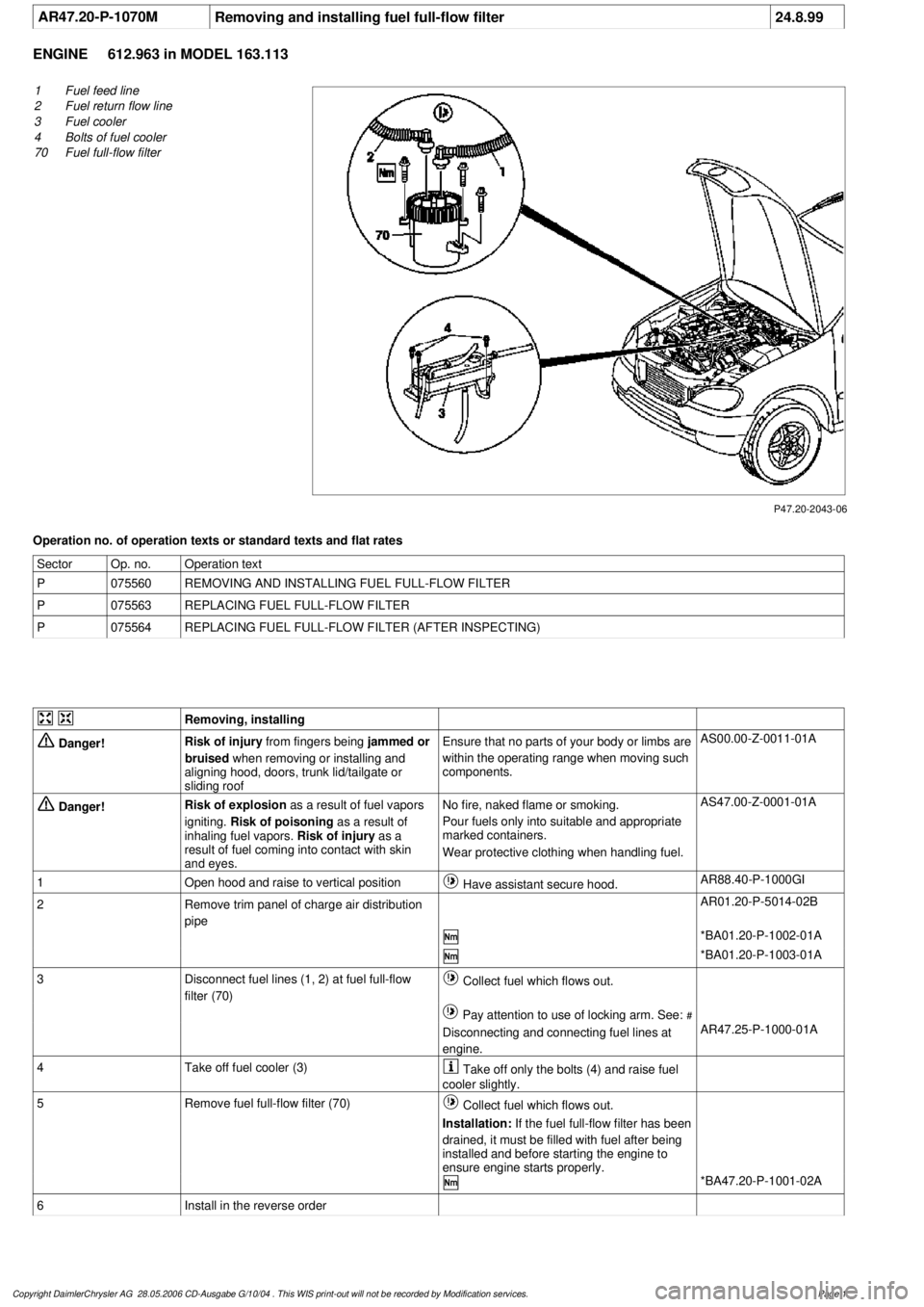
P47.20-2043-06
1
Fuel feed line
2
Fuel return flow line
3
Fuel cooler
4
Bolts of fuel cooler
70
Fuel full-flow filter
Operation no. of operation texts or standard texts and flat rates
Sector
Op. no.
Operation text
P
075560
REMOVING AND INSTALLING FUEL FULL-FLOW FILTER
P
075563
REPLACING FUEL FULL-FLOW FILTER
P
075564
REPLACING FUEL FULL-FLOW FILTER (AFTER INSPECTING)
Removing, installing
Danger!
Risk of injury
from fingers being
jammed or
bruised
when removing or installing and
aligning hood, doors, trunk lid/tailgate or
sliding roof
Ensure that no parts of your body or limbs are
within the operating range when moving such
components.
AS00.00-Z-0011-01A
Danger!
Risk of explosion
as a result of fuel vapors
igniting.
Risk of poisoning
as a result of
inhaling fuel vapors.
Risk of injury
as a
result of fuel coming into contact with skin
and eyes.
No fire, naked flame or smoking.
Pour fuels only into suitable and appropriate
marked containers.
Wear protective clothing when handling fuel.
AS47.00-Z-0001-01A
1
Open hood and raise to vertical position
Have assistant secure hood.
AR88.40-P-1000GI
2
Remove trim panel of charge air distribution
pipe
AR01.20-P-5014-02B
*BA01.20-P-1002-01A
*BA01.20-P-1003-01A
3
Disconnect fuel lines (1, 2) at fuel full-flow
filter (70)
Collect fuel which flows out.
Pay attention to use of locking arm. See:
#
Disconnecting and connecting fuel lines at
engine.
AR47.25-P-1000-01A
4
Take off fuel cooler (3)
Take off only the bolts (4) and raise fuel
cooler slightly.
5
Remove fuel full-flow filter (70)
Collect fuel which flows out.
Installation:
If the fuel full-flow filter has been
drained, it must be filled with fuel after being
installed and before starting the engine to
ensure engine starts properly.
*BA47.20-P-1001-02A
6
Install in the reverse order
Copyright DaimlerChrysler AG 28.05.2006 CD-Ausgabe G/10/04 . This WIS print-out will not be recorde
d by Modification services.
Page 1
Page 2592 of 4133

Danger!
Risk of accident
as a result of vehicle
starting off when engine running.
Risk of
injury as a result of bruises and burns if you
insert your hands into engine when it is being
started or when it is running.
Secure vehicle to prevent it starting off.
Wear closed and close-fitting work clothes.
Do not grasp hot or rotating parts.
AS00.00-Z-0005-01A
7
Run engine and inspect fuel system for leaks
Crankcase ventilation, cylinder head cover
Number
Designation
Engine
612.963
BA01.20-P-1002-01A
Screw of trim panel of cylinder head cover
to cylinder head cover
Nm
10
BA01.20-P-1003-01A
Screw of trim panel of charge air distribution
pipe to charge air distribution pipe
Nm
10
Fuel filter
Number
Designation
Engine
612.961/
963
BA47.20-P-1001-02A
Bolt of fuel filter to charge air distribution pipe
Nm
14
Copyright DaimlerChrysler AG 28.05.2006 CD-Ausgabe G/10/04 . This WIS print-out will not be recorde
d by Modification services.
Page 2
Page 2594 of 4133

2.1
Disconnect fuel lines (1,2) at main fuel filter
(70)
Engine 611
Collect escaping fuel.
Pay attention to use of locking arm. Refer
to:
#
Separate fuel lines from engine, reconnect
AR47.25-P-1000-01A
2.2
Disconnect fuel lines (1,2,3,4) at main fuel
filter (70)
Engine 612, 613
Collect escaping fuel.
Pay attention to use of locking arm. Refer
to:
#
Disconnect, connect fuel lines at engine.
AR47.25-P-1000-01A
3
Remove main fuel filter (70)
If the main fuel filter has been emptied, it
must be filled with fuel after being installed
before starting, the engine starts more easily.
*BA47.20-P-1001-02A
4
Install in the reverse order
Danger!
Risk of accident
due to automatic starting-off
when engine is running.
Injury hazard
due to
crimped connection and combustion when
meshing during starting procedure or when
engine is running
Secure vehicle to prevent it from moving off
by itself.
Wear closed and close-fitting work clothes.
Do not grasp hot or rotating parts.
AS00.00-Z-0005-01A
5
Run engine and inspect fuel system for leaks
Crankcase ventilation, cylinder head cover
Number
Designation
Engine
611.960/
961/962
Engine
612.961/
962/967
Engine
612.963
Engine
613.960/
961
BA01.20-P-1003-01A
Screw attaching cover panel to charge air
distribution pipe
Nm
10101010
Fuel filter
Number
Designation
Engine
611.960/
961
Engine
611.962
Engine
612.961/
963
Engine
613.960/
961
BA47.20-P-1001-02A
Bolt of fuel filter to charge air distribution pipe
Nm
14141414
Copyright DaimlerChrysler AG 28.05.2006 CD-Ausgabe G/10/04 . This WIS print-out will not be recorde
d by Modification services.
Page 2
Page 2612 of 4133
AR47.10-P-8022GH
Remove/install fuel tank pressure sensor
18.3.97
MODEL
163.154 with ENGINE 112.942 with CODE (494a) USA version
MODEL
163.157 with ENGINE 112.970 with CODE (494a) USA version
MODEL
163.172 with ENGINE 113.942 with CODE (494a) USA version
MODEL
163.174 with ENGINE 113.981 with CODE (494a) USA version
MODEL
163.175 with ENGINE 113.965 with CODE (494a) USA version
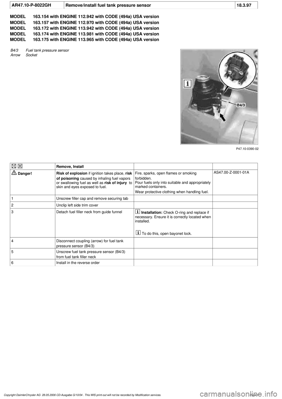
P47.10-0390-02
B4/3Fuel tank pressure sensor
Arrow
Socket
Remove, Install
Danger!
Risk of explosion
if ignition takes place,
risk
of poisoning
caused by inhaling fuel vapors
or swallowing fuel as well as
risk of injury
to
skin and eyes exposed to fuel.
Fire, sparks, open flames or smoking
forbidden.
Pour fuels only into suitable and appropriately
marked containers.
Wear protective clothing when handling fuel.
AS47.00-Z-0001-01A
1
Unscrew filler cap and remove securing tab
2
Unclip left side trim cover
3
Detach fuel filler neck from guide funnel
Installation:
Check O-ring and replace if
necessary. Ensure it is correctly located when
installed.
To do this, open bayonet lock.
4
Disconnect coupling (arrow) for fuel tank
pressure sensor (B4/3)
5
Unscrew fuel tank pressure sensor (B4/3)
from fuel tank filler neck
6
Install in the reverse order
Copyright DaimlerChrysler AG 28.05.2006 CD-Ausgabe G/10/04 . This WIS print-out will not be recorde
d by Modification services.
Page 1
Page 2666 of 4133
The cause for the damage must be determined to ensure that the damage does not reoccur after the wiring
harness has been repaired.
Scope of the damage:
Which components are damaged, can the damage be identified exactly?
Can you be sure that no other components are damaged?
Repair options:
What are the options for repair?
Which replacement parts are available?
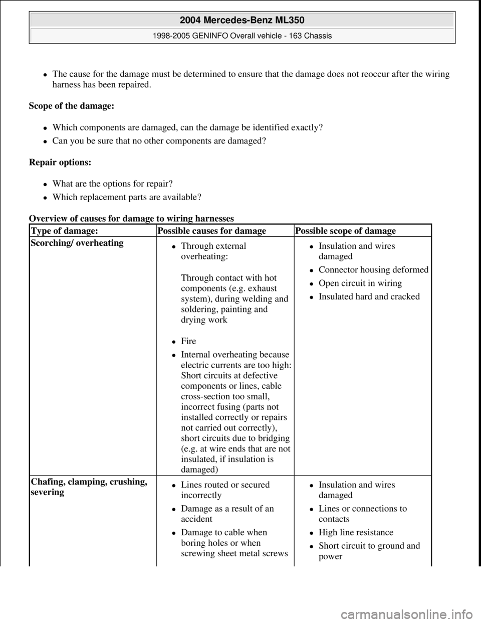
Overview of causes for damage to wiring harnesses
Type of damage:Possible causes for damagePossible scope of damage
Scorching/ overheating Through external
overheating:
Through contact with hot
components (e.g. exhaust
system), during welding and
soldering, painting and
drying work
Fire
Internal overheating because
electric currents are too high:
Short circuits at defective
components or lines, cable
cross-section too small,
incorrect fusing (parts not
installed correctly or repairs
not carried out correctly),
short circuits due to bridging
(e.g. at wire ends that are not
insulated, if insulation is
damaged)
Insulation and wires
damaged
Connector housing deformed
Open circuit in wiring
Insulated hard and cracked
Chafing, clamping, crushing,
severing Lines routed or secured
incorrectly
Damage as a result of an
accident
Damage to cable when
boring holes or when
screwing sheet metal screws
Insulation and wires
damaged
Lines or connections to
contacts
High line resistance
Short circuit to ground and
power
2004 Mercedes-Benz ML350
1998-2005 GENINFO Overall vehicle - 163 Chassis
me
Saturday, October 02, 2010 3:47:44 PMPage 21 © 2006 Mitchell Repair Information Company, LLC.
Page 2667 of 4133
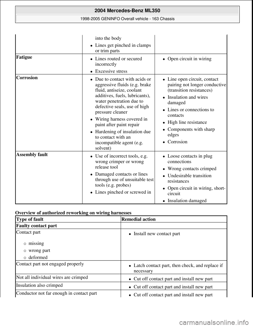
Overview of authorized reworking on wiring harnesses
into the body
Lines get pinched in clamps
or trim parts
Fatigue Lines routed or secured
incorrectly
Excessive stress
Open circuit in wiring
Corrosion Due to contact with acids or
aggressive fluids (e.g. brake
fluid, antiseize, coolant
additives, fuels, lubricants),
water penetration due to
defective seals, use of high
pressure cleaner
Wiring harness covered in
paint after paint repair
Hardening of insulation due
to contact with an
incompatible agent (e.g.
solvent)
Line open circuit, contact
pairing not longer conductive
(transition resistances)
Insulation and wires
damaged
Lines or connections to
contacts
High line resistance
Components with sharp
edges
Corrosion
Assembly fault Use of incorrect tools, e.g.
wrong crimper or wrong
release tool
Damaged contacts or lines
through use of unsuitable test
tools (e.g. probes)
Lines pinched or screwed in
Loose contacts in plug
connections
Wrong contacts crimped
Undesirable transition
resistances
Open circuit in wiring, short-
circuit
Insulation damaged
Type of faultRemedial action
Faulty contact part
Contact part
missing
wrong part
deformed
Install new contact part
Contact part not engaged properlyLatch contact part, then check, and replace if
necessary
Not all individual wires are crimpedCut off contact part and install new part
Insulation also crimpedCut off contact part and install new part
Conductor not far enough in contact partCut off contact part and install new part
2004 Mercedes-Benz ML350
1998-2005 GENINFO Overall vehicle - 163 Chassis
me
Saturday, October 02, 2010 3:47:44 PMPage 22 © 2006 Mitchell Repair Information Company, LLC.
Page 2863 of 4133
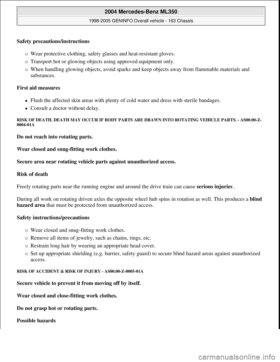
Safety precautions/instructions
Wear protective clothing, safety glasses and heat-resistant gloves.
Transport hot or glowing objects using approved equipment only.
When handling glowing objects, avoid sparks and keep objects away from flammable materials and
substances.
First aid measures
Flush the affected skin areas with plenty of cold water and dress with sterile bandages.
Consult a doctor without delay.
RISK OF DEATH. DEATH MAY OCCUR IF BODY PARTS ARE DRAWN INTO ROTATING VEHICLE PARTS. - AS00.00-Z-
0004-01A
Do not reach into rotating parts.
Wear closed and snug-fitting work clothes.
Secure area near rotating vehicle parts against unauthorized access.
Risk of death
Freely rotating parts near the running engine and around the drive train can cause serious injuries .
During all work on rotating driven axles the opposite wheel hub spins in rotation as well. This produces a blind
hazard area that must be protected from unauthorized access.
Safety instructions/precautions
Wear closed and snug-fitting work clothes.
Remove all items of jewelry, such as chains, rings, etc.
Restrain long hair by wearing an appropriate head cover.
Set up appropriate shielding (e.g. barrier, safety guard) to secure blind hazard areas against unauthorized
access.
RISK OF ACCIDENT & RISK OF INJURY - AS00.00-Z-0005-01A
Secure vehicle to prevent it from moving off by itself.
Wear closed and close-fitting work clothes.
Do not grasp hot or rotating parts.
Possible hazards
2004 Mercedes-Benz ML350
1998-2005 GENINFO Overall vehicle - 163 Chassis
me
Saturday, October 02, 2010 3:47:47 PMPage 218 © 2006 Mitchell Repair Information Company, LLC.
Page 2864 of 4133
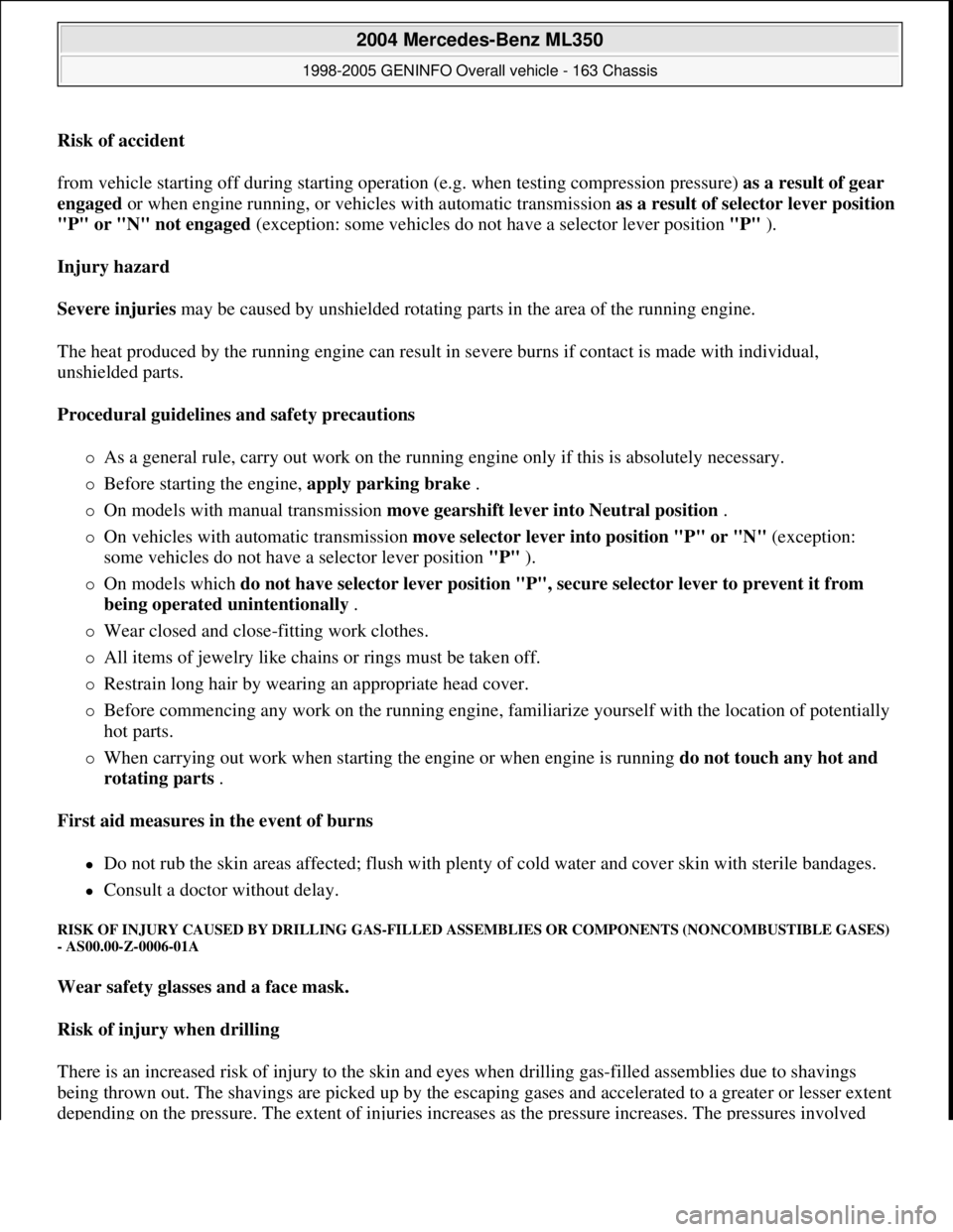
Risk of accident
from vehicle starting off during starting operation (e.g. when testing compression pressure) as a result of gear
engaged or when engine running, or vehicles with automatic transmission as a result of selector lever position
"P" or "N" not engaged (exception: some vehicles do not have a selector lever position "P" ).
Injury hazard
Severe injuries may be caused by unshielded rotating parts in the area of the running engine.
The heat produced by the running engine can result in severe burns if contact is made with individual,
unshielded parts.
Procedural guidelines and safety precautions
As a general rule, carry out work on the running engine only if this is absolutely necessary.
Before starting the engine, apply parking brake .
On models with manual transmission move gearshift lever into Neutral position .
On vehicles with automatic transmission move selector lever into position "P" or "N" (exception:
some vehicles do not have a selector lever position "P" ).
On models which do not have selector lever position "P", secure selector lever to prevent it from
being operated unintentionally .
Wear closed and close-fitting work clothes.
All items of jewelry like chains or rings must be taken off.
Restrain long hair by wearing an appropriate head cover.
Before commencing any work on the running engine, familiarize yourself with the location of potentially
hot parts.
When carrying out work when starting the engine or when engine is running do not touch any hot and
rotating parts .
First aid measures in the event of burns
Do not rub the skin areas affected; flush with plenty of cold water and cover skin with sterile bandages.
Consult a doctor without delay.
RISK OF INJURY CAUSED BY DRILLING GAS-FILLED ASSEMBLIES OR COMPONENTS (NONCOMBUSTIBLE GASES)
- AS00.00-Z-0006-01A
Wear safety glasses and a face mask.
Risk of injury when drilling
There is an increased risk of injury to the skin and eyes when drilling gas-filled assemblies due to shavings
being thrown out. The shavings are picked up by the escaping gases and accelerated to a greater or lesser extent
depending on the pressure. The extent of injuries increases as the pressure increases. The pressures involved
2004 Mercedes-Benz ML350
1998-2005 GENINFO Overall vehicle - 163 Chassis
me
Saturday, October 02, 2010 3:47:47 PMPage 219 © 2006 Mitchell Repair Information Company, LLC.
Page 2866 of 4133
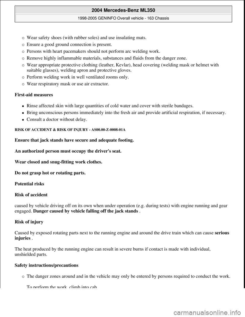
Wear safety shoes (with rubber soles) and use insulating mats.
Ensure a good ground connection is present.
Persons with heart pacemakers should not perform arc welding work.
Remove highly inflammable materials, substances and fluids from the danger zone.
Wear appropriate protective clothing (leather, Kevlar), head covering (welding mask or helmet with
suitable glasses), welding apron and protective gloves.
Perform welding work in well ventilated rooms only.
Wear respiratory mask or use air extractor.
First-aid measures
Rinse affected skin with large quantities of cold water and cover with sterile bandages.
Bring unconscious persons immediately into the fresh air and provide artificial respiration, if necessary.
Consult a doctor without delay.
RISK OF ACCIDENT & RISK OF INJURY - AS00.00-Z-0008-01A
Ensure that jack stands have secure and adequate footing.
An authorized person must occupy the driver's seat.
Wear closed and snug-fitting work clothes.
Do not grasp hot or rotating parts.
Potential risks
Risk of accident
caused by vehicle driving off on its own when under operation (e.g. during tests) with engine running and gear
engaged. Danger caused by vehicle falling off the jack stands .
Risk of injury
Caused by exposed rotating parts next to the running engine and around the drive train which can cause serious
injuries .
The heat produced by the running engine can result in severe burns if contact is made with individual,
unshielded parts.
Safety instructions/precautions
The danger zones around and in the vehicle may only be entered by persons required to conduct the work.
To perform the work, climb into cab.
2004 Mercedes-Benz ML350
1998-2005 GENINFO Overall vehicle - 163 Chassis
me
Saturday, October 02, 2010 3:47:47 PMPage 221 © 2006 Mitchell Repair Information Company, LLC.