ECU MERCEDES-BENZ ML350 1997 Complete Repair Manual
[x] Cancel search | Manufacturer: MERCEDES-BENZ, Model Year: 1997, Model line: ML350, Model: MERCEDES-BENZ ML350 1997Pages: 4133, PDF Size: 88.89 MB
Page 3499 of 4133
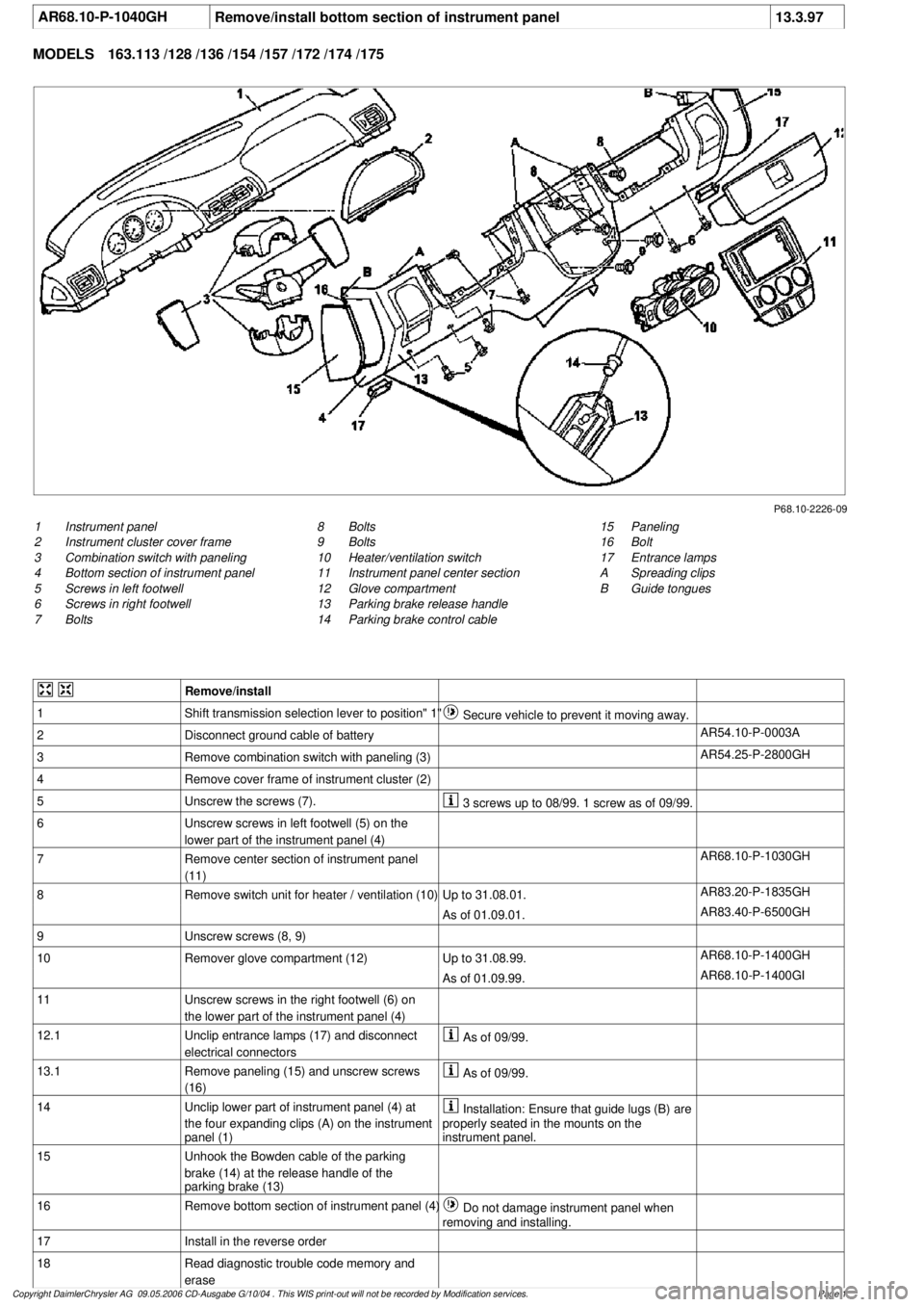
AR68.10-P-1040GH
Remove/install bottom section of instrument panel
13.3.97
MODELS
163.113 /128 /136 /154 /157 /172 /174 /175
P68.10-2226-09
1
Instrument panel
2
Instrument cluster cover frame
3
Combination switch with paneling
4
Bottom section of instrument panel
5
Screws in left footwell
6
Screws in right footwell
7
Bolts
15
Paneling
16
Bolt
17
Entrance lamps
A
Spreading clips
B
Guide tongues
8
Bolts
9
Bolts
10
Heater/ventilation switch
11
Instrument panel center section
12
Glove compartment
13
Parking brake release handle
14
Parking brake control cable
Remove/install
1
Shift transmission selection lever to position" 1"
Secure vehicle to prevent it moving away.
2
Disconnect ground cable of battery
AR54.10-P-0003A
3
Remove combination switch with paneling (3)
AR54.25-P-2800GH
4
Remove cover frame of instrument cluster (2)
5
Unscrew the screws (7).
3 screws up to 08/99. 1 screw as of 09/99.
6
Unscrew screws in left footwell (5) on the
lower part of the instrument panel (4)
7
Remove center section of instrument panel
(11)
AR68.10-P-1030GH
8
Remove switch unit for heater / ventilation (10)
Up to 31.08.01.
AR83.20-P-1835GH
As of 01.09.01.
AR83.40-P-6500GH
9
Unscrew screws (8, 9)
10
Remover glove compartment (12)
Up to 31.08.99.
AR68.10-P-1400GH
As of 01.09.99.
AR68.10-P-1400GI
11
Unscrew screws in the right footwell (6) on
the lower part of the instrument panel (4)
12.1
Unclip entrance lamps (17) and disconnect
electrical connectors
As of 09/99.
13.1
Remove paneling (15) and unscrew screws
(16)
As of 09/99.
14
Unclip lower part of instrument panel (4) at
the four expanding clips (A) on the instrument
panel (1)
Installation: Ensure that guide lugs (B) are
properly seated in the mounts on the
instrument panel.
15
Unhook the Bowden cable of the parking
brake (14) at the release handle of the
parking brake (13)
16
Remove bottom section of instrument panel (4)
Do not damage instrument panel when
removing and installing.
17
Install in the reverse order
18
Read diagnostic trouble code memory and
erase
Copyright DaimlerChrysler AG 09.05.2006 CD-Ausgabe G/10/04 . This WIS print-out will not be recorde
d by Modification services.
Page 1
Page 3518 of 4133
AR07.52-P-1465A
Remove/install intake air temperature sensor
16.2.99
ENGINE
604, 611.960 /961 /962, 612.961 /962 /963 /967, 613.961 /960, 628.960
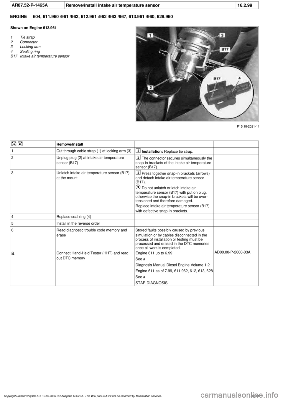
P15.18-2021-11
Shown on Engine 613.961
1
Tie strap
2
Connector
3
Locking arm
4
Sealing ring
B17
Intake air temperature sensor
Remove/Install
1
Cut through cable strap (1) at locking arm (3)
Installation:
Replace tie strap.
2
Unplug plug (2) at intake air temperature
sensor (B17)
The connector secures simultaneously the
snap-in brackets of the intake air temperature
sensor (B17).
3
Unlatch intake air temperature sensor (B17)
at the mount
Press together snap-in brackets (arrows)
and detach intake air temperature sensor
(B17).
Do not unlatch or latch intake air
temperature sensor (B17) with put on plug,
otherwise the snap-in brackets will be over-
tensioned and therefore damaged.
Replace intake air temperature sensor (B17)
with defective snap-in brackets.
4
Replace seal ring (4)
5
Install in the reverse order
6
Read diagnostic trouble code memory and
erase
Stored faults possibly caused by previous
simulation or by cables disconnected in the
process of installation or testing must be
processed and erased in the DTC memories
once all work is completed.
a
Connect Hand-Held Tester (HHT) and read
out DTC memory
Engine 611 up to 6.99
See
#
AD00.00-P-2000-03A
Diagnosis Manual Diesel Engine Volume 1.2
Engine 611 as of 7.99, 611.962, 612, 613, 628
See
#
STAR DIAGNOSIS
Copyright DaimlerChrysler AG 12.05.2006 CD-Ausgabe G/10/04 . This WIS print-out will not be recorde
d by Modification services.
Page 1
Page 3538 of 4133
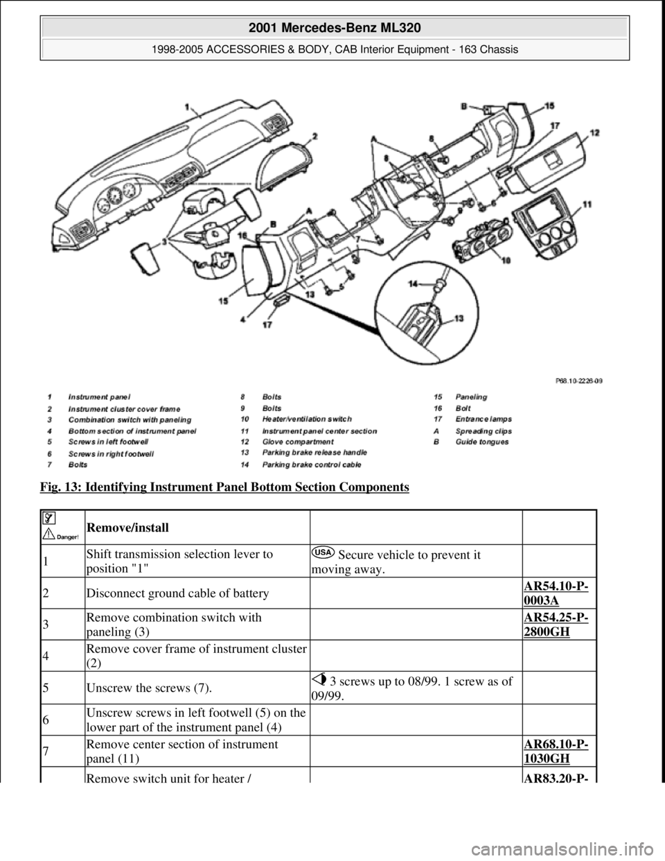
Fig. 13: Identifying Instrument Panel Bottom Section Components
Remove/install
1Shift transmission selection lever to
position "1" Secure vehicle to prevent it
moving away.
2Disconnect ground cable of battery AR54.10-P-
0003A
3Remove combination switch with
paneling (3) AR54.25-P-
2800GH
4Remove cover frame of instrument cluster
(2)
5Unscrew the screws (7). 3 screws up to 08/99. 1 screw as of
09/99.
6Unscrew screws in left footwell (5) on the
lower part of the instrument panel (4)
7Remove center section of instrument
panel (11) AR68.10-P-
1030GH
Remove switch unit for heater / AR83.20-P-
2001 Mercedes-Benz ML320
1998-2005 ACCESSORIES & BODY, CAB Interior Equipment - 163 Chassis
me
Saturday, October 02, 2010 3:35:21 PMPage 20 © 2006 Mitchell Repair Information Company, LLC.
Page 3575 of 4133
Safety belts/emergency tensioning retractors
Luggage nets
Child seats
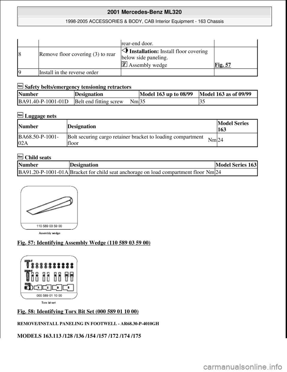
Fig. 57: Identifying Assembly Wedge (110 589 03 59 00)
Fig. 58: Identifying Torx Bit Set (000 589 01 10 00)
REMOVE/INSTALL PANELING IN FOOTWELL - AR68.30-P-4010GH
MODELS 163.113 /128 /136 /154 /157 /172 /174 /175
rear-end door.
8Remove floor covering (3) to rear Installation: Install floor covering
below side paneling.
Assembly wedgeFig. 57
9Install in the reverse order
NumberDesignationModel 163 up to 08/99Model 163 as of 09/99
BA91.40-P-1001-01DBelt end fitting screwNm3535
NumberDesignationModel Series
163
BA68.50-P-1001-
02ABolt securing cargo retainer br acket to loading compartment
floorNm24
NumberDesignationModel Series 163
BA91.20-P-1001-01ABracket for child seat anchorage on load compartment floorNm24
2001 Mercedes-Benz ML320
1998-2005 ACCESSORIES & BODY, CAB In terior Equipment - 163 Chassis
me
Saturday, October 02, 2010 3:35:22 PMPage 57 © 2006 Mitchell Repair Information Company, LLC.
Page 3605 of 4133
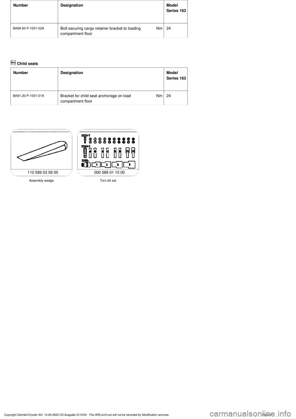
Number
Designation
Model
Series 163
BA68.50-P-1001-02A
Bolt securing cargo retainer bracket to loading
compartment floor
Nm
24
Child seats
Number
Designation
Model
Series 163
BA91.20-P-1001-01A
Bracket for child seat anchorage on load
compartment floor
Nm
24
000 589 01 10 00
Torx bit set
Assembly wedge
110 589 03 59 00
Copyright DaimlerChrysler AG 14.06.2006 CD-Ausgabe G/10/04 . This WIS print-out will not be recorde
d by Modification services.
Page 2
Page 3651 of 4133
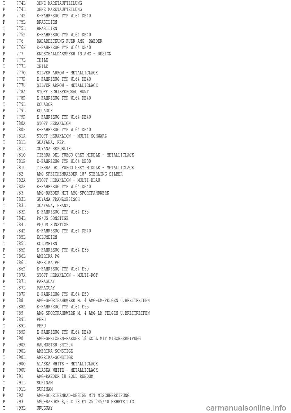
T 774L OHNE MARKTAUFTEILUNG
P 774L OHNE MARKTAUFTEILUNG
P 774P E-FAHRZEUG TYP W164 DE40
P 775L BRASILIEN
T 775L BRASILIEN
P 775P E-FAHRZEUG TYP W164 DE40
P 776 RADABDECKUNG FUER AMG -RAEDER
P 776P E-FAHRZEUG TYP W164 DE40
P 777 ENDSCHALLDAEMPFER IN AMG - DESIGN
P 777L CHILE
T 777L CHILE
P 777O SILVER ARROW - METALLICLACK
P 777P E-FAHRZEUG TYP W164 DE40
P 777U SILVER ARROW - METALLICLACK
P 778A STOFF SCHIEFERGRAU BUNT
P 778P E-FAHRZEUG TYP W164 DE40
T 779L ECUADOR
P 779L ECUADOR
P 779P E-FAHRZEUG TYP W164 DE40
P 780A STOFF HERAKLION
P 780P E-FAHRZEUG TYP W164 DE40
P 781A STOFF HERAKLION - MULTI-SCHWARZ
T 781L GUAYANA, REP.
P 781L GUYANA REPUBLIK
P 781O TIERRA DEL FUEGO GREY MIDDLE - METALLICLACK
P 781P E-FAHRZEUG TYP W164 DE30
P 781U TIERRA DEL FUEGO GREY MIDDLE - METALLICLACK
P 782 AMG-SPEICHENRAEDER 18" STERLING SILBER
P 782A STOFF HERAKLION - MULTI-BLAU
P 782P E-FAHRZEUG TYP W164 DE40
P 783 AMG-RAEDER MIT AMG-SPORTFAHRWERK
P 783L GUYANA FRANZOESISCH
T 783L GUAYANA, FRANZ.
P 783P E-FAHRZEUG TYP W164 E35
P 784L PG/US SONSTIGE
T 784L PG/US SONSTIGE
P 784P E-FAHRZEUG TYP W164 DE40
P 785L KOLUMBIEN
T 785L KOLUMBIEN
P 785P E-FAHRZEUG TYP W164 E35
T 786L AMERIKA PG
P 786L AMERIKA PG
P 786P E-FAHRZEUG TYP W164 E50
P 787A STOFF HERAKLION - MULTI-ROT
P 787L PARAGUAY
T 787L PARAGUAY
P 787P E-FAHRZEUG TYP W164 E50
P 788 AMG-SPORTFAHRWERK M. 4 AMG-LM-FELGEN U.BREITREIFEN
P 788P E-FAHRZEUG TYP W164 E55
P 789 AMG-SPORTFAHRWERK M. 4 AMG-LM-FELGEN U.BREITREIFEN
P 789L PERU
T 789L PERU
P 789P E-FAHRZEUG TYP W164 DE40
P 790 AMG-SPEICHEN-RAEDER 18 ZOLL MIT MISCHBEREIFUNG
P 790K BAUMUSTER SRT204
P 790L AMERIKA-SONSTIGE
T 790L AMERIKA-SONSTIGE
P 790O ALASKA WHITE - METALLICLACK
P 790U ALASKA WHITE - METALLICLACK
P 791 AMG-RAEDER 18 ZOLL RUNDUM
T 791L SURINAM
P 791L SURINAM
P 792 AMG-SCHEIBENRAD-DESIGN MIT MISCHBEREIFUNG
P 793 AMG-RAEDER 8,5 X 18 ET 25 245/40 MEHRTEILIG
T 793L URUGUAY
Page 3730 of 4133

GF77.20-P-2003GH
Opening pop-up roof, function
19.2.97
MODEL
163 with CODE (414a) Electric glass sliding/pop-up roof
Function prerequisites
D
Voltage not too low or too high
D
Switch-on conditions for convenience control fulfilled
D
Sliding/pop-up roof synchronized
Function
When
switch (SHD, S13/2)
is actuated continuously, circuit 30 is
switched through to the
sliding/pop-up roof (M12)
and the pop-up
roof opens.
The function "Open pop-up roof" is executed as long as
D
switch (SHD, S13/2)
is actuated and
D
the pop-up roof has not yet reached the end position and
D
lock-up is not recognized.
If the sliding/pop-up roof is desynchronized, it moves only in the pop-
up roof direction each time the
switch (SHD, S13/2)
is actuated. This
means that it is possible to move to the zero
position for synchronizing. After successful
synchronization
, the
sliding/pop-up roof can be controlled again without limitation.
Vehicles
up to 11.99:
The power for the
sliding/pop-up roof (M12)
is supplied via a
fuse directly to c. 30.
The power for the
switch (SR, S13/2)
is supplied via the
convenience relay (F1k14)
, which is actuated by the all-
activity module (AAM, N10).
Vehicles
as of 12.99:
The power for the
sliding/pop-up roof (M12)
is supplied via a
fuse directly to c. 30. The power for the
switch (SHD, S13/2) is
supplied via a lead to the
extended-activity module (EAM,
N10/1) , this power is switched through only when the switch-on
conditions for the convenience control are fulfilled and the EAM
is coded accordingly.
Closing sliding /pop-up roof, function
GF77.20-P-2002GH
Sliding /pop-up roof lock-up recognition,
function
GF77.20-P-3000GH
Sliding /pop-up roof position measurement,
function
GF77.20-P-3001GH
Synchronizing sliding /pop-up roof, function
GF77.20-P-3002GH
Convenience control
GF72.29-P-2002GH
All-activity module (AAM)
up to 11.99
GF54.21-P-4100GH
Extended-activity module, location/
purpose/design/function
as of 12.99
GF54.21-P-4107GK
Copyright DaimlerChrysler AG 04.08.2006 CD-Ausgabe G/10/04 . This WIS print-out will not be recorde
d by Modification services.
Page 1
Page 3757 of 4133

3.1
Remove viscous fan (1)
Engine 112.942 /970 and 113.942.
Right-hand thread!
AR20.40-P-5660C
3.2
Remove electric fan
Only Engine 113.965 /981.
AR20.40-P-5000GH
4.1
Pull off plate clamps of fan shroud (2)
Only for Engine 112.942, from 5/98.
5.1
Remove fan shroud (3)
Only for Engine 112.942 /970 und
113.942. Unscrew the bolts at bottom of fan
shroud for this step
Installation:
If installing a new radiator
with integral power steering pump oil cooler, a
new fan shroud is required if a radiator
without integral oil cooler was previously
installed.
6
Remove headlamp (7).
AR82.10-P-4730GH
7
Remove radiator crossmember (8)
AR62.30-P-2300GH
8
Detach coolant line (4, 6) and expansion
reservoir coolant line (5) at the radiator
Installation:
Replace the hose clamps on
the radiator fitting for the coolant hose, as
they could cause damage to the screw/thread.
Hose clamp
*BA20.20-P-1004-01A
9
Remove the rubber seal on radiator (9)
10.1
Remove oil line (return line of radiator
!
power steering pump expansion reservoir)
(18) and oil line (feed line of steering gear
!
radiator) (19)
From 5/98 only, seal off the connections.
Set of plugs
*129589009100
11
Unscrew ATF lines (10) at the radiator
Seal off the connections.
*BA20.20-P-1001-01A
*BA20.20-P-1003-01A
Set of plugs
*129589009100
12.1
Detach the connector from the fan and
remove the fan grille (11)
Only for Engine 112.942 /970 and 113.942.
13
Unscrew the condenser from the radiator
Do not disconnect the lines.
14
Remove fasteners (20) and damper rubber
(21)
The damper rubber (21) is designed to
prevent possible vibrations between the
condenser and radiator (15) during off-road
driving.
15
Remove air conditioning system fluid
reservoir (14) from the radiator
Place aside with the lines connected.
Detach the condenser from the radiator.
16
Remove radiator (15)
When installing, the spigots on the
radiator must be inserted in the rubber
grommets in the bottom crossmember.
Installation:
On Model 163.154 with
Engine 112.942 before VIN end number
043553, when installing a new radiator with
integral power steering pump oil cooler,
additional operations are required, if they
have not already been carried out:
#
v
Retrofit the bracket for the oil cooler line of
the power steering pump
SM46.30-P-0002A
k
Radiator with integral oil cooler for the power
steering pump
BT20.20-P-0001-01A
17
Detach air guides (12)
Replace the clamps on air guides (13).
18
Install in the reverse order
19
Pour in coolant
AR20.00-P-1142HA
20
Check the headlamp setting and correct if
necessary
e
Check and adjust the headlamp setting
AP82.10-P-8260GH
Danger!
Risk of accident
caused by vehicle starting
off when engine is running.
Risk of injury
caused by contusions and burns when
working in engine during starting procedure
Secure the vehicle to prevent it from moving.
Wear closed and snug-fitting work clothes.
Do not grasp hot or rotating parts.
AS00.00-Z-0005-01A
21
Check the oil level in the automatic
transmission and correct if necessary
AR27.00-P-0101A
22
Check the cooling system for leaks
AR20.00-P-1010HA
Radiator, coolant hoses
Copyright DaimlerChrysler AG 12.05.2006 CD-Ausgabe G/10/04 . This WIS print-out will not be recorde
d by Modification services.
Page 2
Page 3759 of 4133
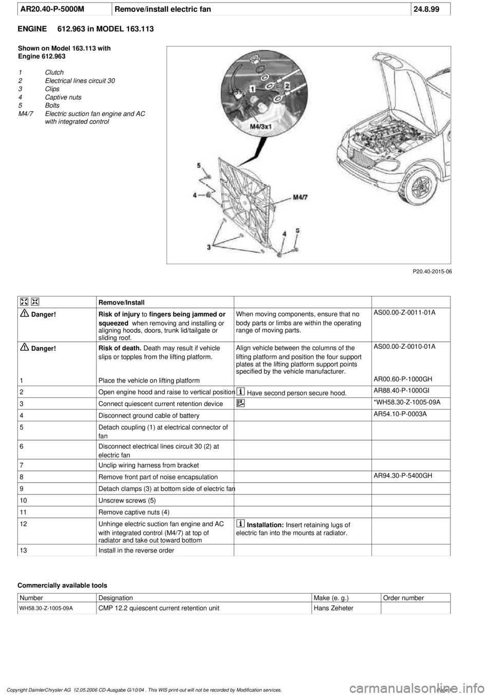
AR20.40-P-5000M
Remove/install electric fan
24.8.99
ENGINE
612.963 in MODEL 163.113
P20.40-2015-06
Shown on Model 163.113 with
Engine 612.963
1
Clutch
2
Electrical lines circuit 30
3
Clips
4
Captive nuts
5
Bolts
M4/7
Electric suction fan engine and AC
with integrated control
Remove/Install
Danger!
Risk of injury
to
fingers being jammed or
squeezed
when removing and installing or
aligning hoods, doors, trunk lid/tailgate or
sliding roof.
When moving components, ensure that no
body parts or limbs are within the operating
range of moving parts.
AS00.00-Z-0011-01A
Danger!
Risk of death.
Death may result if vehicle
slips or topples from the lifting platform.
Align vehicle between the columns of the
lifting platform and position the four support
plates
at the lifting platform support points
specified by the vehicle manufacturer.
AS00.00-Z-0010-01A
1
Place the vehicle on lifting platform
AR00.60-P-1000GH
2
Open engine hood and raise to vertical position
Have second person secure hood.
AR88.40-P-1000GI
3
Connect quiescent current retention device
*WH58.30-Z-1005-09A
4
Disconnect ground cable of battery
AR54.10-P-0003A
5
Detach coupling (1) at electrical connector of
fan
6
Disconnect electrical lines circuit 30 (2) at
electric fan
7
Unclip wiring harness from bracket
8
Remove front part of noise encapsulation
AR94.30-P-5400GH
9
Detach clamps (3) at bottom side of electric fan
10
Unscrew screws (5)
11
Remove captive nuts (4)
12
Unhinge electric suction fan engine and AC
with integrated control (M4/7) at top of
radiator and take out toward bottom
Installation:
Insert retaining lugs of
electric fan into the mounts at radiator.
13
Install in the reverse order
Commercially available tools
Number
Designation
Make (e. g.)
Order number
WH58.30-Z-1005-09A
CMP 12.2 quiescent current retention unit
Hans Zeheter
Copyright DaimlerChrysler AG 12.05.2006 CD-Ausgabe G/10/04 . This WIS print-out will not be recorde
d by Modification services.
Page 1
Page 3761 of 4133

Danger!
Risk of injury
to skin and eyes suffering
scalding from contact with hot coolant spray.
Risk of poisoning
from swallowing coolant.
Do not open cooling system unless coolant
temperature is below 90 °C. Open cap slowly
and release the pressure. Do not pour coolant
into beverage bottles.
Wear protective gloves, protective clothing
and eye protection.
AS20.00-Z-0001-01A
1
Open engine hood and raise to vertical position
Have second person secure hood.
AR88.40-P-1000GI
2
Connect no load current retention unit
*WH58.30-Z-1005-09A
3
Disconnect battery ground cable
AR54.10-P-0003A
4
Remove trim panel of cylinder head cover
AR01.20-P-5014-02B
*BA01.20-P-1002-01A
*BA01.20-P-1003-01A
5
Remove bottom part of noise encapsulation
at front
AR94.30-P-5400GH
6
Remove electric fan (1)
Remove toward bottom.
AR20.40-P-5000M
7
Drain coolant
At radiator.
AR20.00-P-1142M
Notes on coolant
All engines
AH20.00-N-2080-01A
8
Remove charge air cooler (110/2)
AR09.41-P-6817MM
9.1
Attach guard plate for radiator/condenser
With automatic air conditioning, code
581a and AC system or Tempmatic USA,
code 580.
Attach additional AC condenser in the
vehicle.
y
Guard plate for radiator/condenser
Engine 606 in model 124,
Engine 606.961 in model 140,
Engine 112, 113, 604, 605, 611.960 in
MODEL 202,
Engine 602.983, 612.966 in MODEL 461,
Engine 628.962, 612.965, 606.964, 112.945,
113.962/ 982 in MODEL 463,
Engine 111, 112, 611.962, 612.962 in model
203,
Engines 112, 113, 611.961, 612.961, 613.961
in MODEL 210,
Engine 112 in model 170,
Engine 112 in MODEL 220,
Engine 113 in MODEL 211, 215, 220,
Engine 112 in MODEL 208,
Engine 112, 612.963, 628.963 in MODEL 163,
Engine 112.923 /943, 113.961 in MODEL 129,
Engine 137, 275 in MODEL 215, 220,
Engine 613.960, 628.960 in MODEL 220,
Engine 113.992 in model 230.474,
Engine 271 in model 209, 203,
Engine 285.950 in model 240.078 /178,
Engine 612.967 in model 209.316,
Engine 648 in model 220
Engine 112.951 in model 639.601/603/
605/701/703/705/801/803/805
Engine 646.983/984 in model 639.601/
603/605/701/703/705/801/803/805
Engine 646.982 in model
639.601/603/605/701/703/705
WF58.50-P-0110-01A
10
Remove seal rail (11)
11
Extract steering oil from reservoir
Hand pump
*210589007100
12.1
Disconnect power steering oil line (return line
radiator
!
power steering pump supply
reservoir) (18)
Seal connections.
Installation:
Install new sealing rings.
*BA46.30-P-1012-01A
Clamp
*000589543700
Set of stop plugs
*129589009100
12.2
Disconnect power steering oil line (feed line of
steering gear
!
radiator) (19)
Clamp
*000589543700
Set of stop plugs
*129589009100
Hexagon socket wrench
*WH58.30-Z-1001-06A
Hexagon socket wrench
*WH58.30-Z-1002-06A
Copyright DaimlerChrysler AG 12.05.2006 CD-Ausgabe G/10/04 . This WIS print-out will not be recorde
d by Modification services.
Page 2