ECU MERCEDES-BENZ ML350 1997 Complete Repair Manual
[x] Cancel search | Manufacturer: MERCEDES-BENZ, Model Year: 1997, Model line: ML350, Model: MERCEDES-BENZ ML350 1997Pages: 4133, PDF Size: 88.89 MB
Page 3226 of 4133
A/C EVAPORATOR HOUSING UNIT
Removal & Installation
1. Drain engine coolant. Remove coolant expansion reservoir nuts, disconnect hoses and remove reservoir.
Discharge A/C system, using approved refrigerant recovery/recycling equipment.
2. Remove expansion valve self-locking nut and discard. See Fig. 5
. Disconnect refrigerant lines from
expansion valve. Plug exposed refrigerant lines to protect A/C system from moisture and debris.
3. Remove instrument panel. See INSTRUMENT PANEL
. Remove Electronic Transmission Control
(ETC) module. See Fig. 4
. Disconnect air mix flap actuator connector.
4. Disconnect recirculated air flap element. Disconnect evaporator temperature sensor. Disconnect blower
motor resistor and blower motor connectors. Remove A/C push button control module. Release wiring
harness.
5. Remove insulating mat. See Fig. 5
. Disconnect water drain hose from bottom of A/C housing. Release
A/C housing-to-air distributor clips and remove A/C housing upward. To install, reverse removal
procedure. Recode radio. See RECODING RADIO
under PROGRAMMING. WARNING:To avoid injury from accidental air bag deployment, read and carefully
follow all SERVICE PRECAUTIONS and DISABLING & ACTIVATING AIR
BAG SYSTEM procedures in AIR BAG SYSTEM SAFETY article in
GENERAL SERVICING.
CAUTION: Before disconnecting battery, obtain 5-digit radio security code from
vehicle owner. Radio will be disabled until properly recoded.
2001 Mercedes-Benz ML320
2000-01 MANUAL A/C-HEATER SYSTEMS ML 320, ML 430 & ML 55
me
Saturday, October 02, 2010 3:25:10 PMPage 15 © 2006 Mitchell Repair Information Company, LLC.
Page 3228 of 4133
A/C housing. Disconnect control module connector. To install reverse removal procedure. Recode 5-digit radio
security code. Using HHT, check for DTC and erase, and set clock.
A/C PUSH BUTTON CONTROL PANEL
Removal & Installation
1. Obtain 5-digit radio security code from vehicle owner. Disconnect negative battery cable. Using radio
removal plates, remove radio. Disconnect electrical connectors.
2. Remove instrument panel center section. Remove 4 A/C control panel screws and remove control panel.
Release pull cables and disconnect connectors. To install, reverse removal procedure. Recode radio. See
RECODING RADIO
under PROGRAMMING.
BLOWER MOTOR
Removal & Installation
Remove passenger-side instrument panel under cover. Remove blower motor mounting screws from A/C
housing unit. Disconnect blower motor connector and remove blower motor. To install, reverse removal
procedure.
COMPRESSOR
Removal & Installation
1. Discharge A/C system, using approved refrigerant recovery/recycling equipment. Remove accessory
drive belt. Disconnect low pressure refrigerant line from compressor. Discard "O" rings. Plug exposed
openings to protect A/C system from debris and moisture.
2. Disconnect high pressure refrigerant line from compressor. Discard "O" rings. Plug exposed openings to
protect A/C system from debris and moisture. Disconnect electrical connector. Remove compressor
mounting bolts.
3. Raise and support vehicle. Remove compressor from under vehicle without spilling refrigerant oil. To
install, reverse removal procedure. Ensure refrigerant oil quantity in compressor is correct. See
COMPRESSOR REFRIGERANT OIL CHECKING under GENERAL SERVICING. Tighten bolts to
specification. See TORQUE SPECIFICATIONS
.
CONDENSER
Removal & Installation
1. Discharge A/C system, using approved refrigerant recovery/recycling equipment. Remove cooling fans.
See COOLING FANS
. Disconnect refrigerant line from receiver-drier. See Fig. 5 . Discard "O" rings.
2. Plug exposed openings to protect A/C system from debris and moisture. Remove refrigerant line from
condenser. Remove radiator upper rubber seal. See Fig. 6
. Remove condenser upper mounting screws.
Lift condenser upward and remove. NOTE: Each time A/C compressor is removed and installed, receiver-drier must be
replaced.
2001 Mercedes-Benz ML320
2000-01 MANUAL A/C-HEATER SYSTEMS ML 320, ML 430 & ML 55
me
Saturday, October 02, 2010 3:25:10 PMPage 17 © 2006 Mitchell Repair Information Company, LLC.
Page 3232 of 4133
Fig. 6: Removing Cooling Fans & Condenser
Courtesy of MERCEDES-BENZ OF NORTH AMERICA.
COOLING FANS
Removal & Installation
Remove headlight units. Remove upper frame crossmember, release hood release control cable and remove
crossmember. See Fig. 6
. Remove 2 cooling fans frame bolts on radiator. Disconnect cooling fan connector.
Release outside temperature sensor wiring harness. Pull up on cooling fan and remove. To install, reverse
removal procedure. Ensure cooling fan bottom guides are properly seated in lower mounts.
EVAPORATOR
Removal & Installation
Remove A/C housing unit. See A/C HOUSING UNIT . Remove expansion valve. See Fig. 5 . Discard "O"
rings. Disassemble A/C housing unit. Remove evaporator. Remove evaporator temperature sensor. To install,
reverse removal procedure. Use NEW "O" rings lubricated with refrigerant oil. If installing a new or repair
evaporator, add 1.35 ounces of NEW refrigerant oil to evaporator.
EXPANSION VALVE
Removal & Installation
1. Discharge A/C system, using approved refrigerant recovery/recycling equipment. Without disconnecting
coolant hoses, remove coolant expansion reservoir and set aside. Remove refrigerant line bracket and
loosen clamps. See Fig. 5
. Pull refrigerant lines out of expansion valve.
2. Remove expansion valve self-locking nut and discard. Remove expansion valve. Discard "O" rings. To
install, reverse removal procedure. Use NEW "O" rings lubricated with refrigerant oil. Tighten NEW self-
locking nut to specification. See TORQUE SPECIFICATIONS
.
INSTRUMENT PANEL & INSTRUMENT PANEL CARRIER
Removal & Installation
1. Secure vehicle against rolling. Set transmission selector to "D" position. Obtain radio security code.
Disconnect negative battery cable. Remove driver-side air bag.
2. Place match marks on steering wheel and steering shaft. Remove steering wheel, upper steering column
covers and combination switch. Remove instrument cluster cover frame. Remove one instrument panel
lower section bolt.
3. Remove screws in footwell from left side of instrument panel bottom section. Remove instrument panel
center section. Remove 4 A/C control panel screws and remove control panel. See Fig. 1
. Release pull
cables and disconnect connectors.
4. Remove screws from center section. Remove glove box. Remove screws in footwell from right side of
instrument panel bottom section. Remove entry courtesy lights. Remove end covers and screws.
5. Release 4 "A" clips between instrument panel bottom section and upper section. See Fig. 7
. Release
parkin
g brake release cable from handle. With assistance, remove instrument panel bottom section.
2001 Mercedes-Benz ML320
2000-01 MANUAL A/C-HEATER SYSTEMS ML 320, ML 430 & ML 55
me
Saturday, October 02, 2010 3:25:10 PMPage 21 © 2006 Mitchell Repair Information Company, LLC.
Page 3320 of 4133
The liquefied refrigerant is routed under pressure into the fluid reservoir and flows through a stainless steel
meshing to the filter block. The pores in the filter block are matched precisely to the refrigerant's molecular size.
Thus the refrigerant can flow through the filter block.
All other matter, primarily water, is held back by this molecular filter and deposited. The cleaned refrigerant
flows over a rising pipe to the expansion valve.
Whenever the system is opened, the fluid reservoir should be replaced because of the water which has
collected there in the meantime.
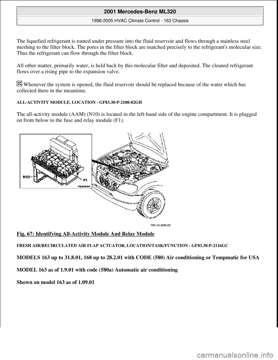
ALL-ACTIVITY MODULE, LOCATION - GF83.30-P-2108-02GH
The all-activity module (AAM) (N10) is located in the left-hand side of the engine compartment. It is plugged
on from below to the fuse and relay module (F1).
Fig. 67: Identifying All
-Activity Module And Relay Module
FRESH AIR/RECIRCULATED AIR FLAP ACTUATOR, LOCATION/TASK/FUNCTION - GF83.30-P-2116GC
MODELS 163 up to 31.8.01, 168 up to 28.2.01 with CODE (580) Air conditioning or Tempmatic for USA
MODEL 163 as of 1.9.01 with code (580a) Automatic air conditioning
Shown on model 163 as of 1.09.01
2001 Mercedes-Benz ML320
1998-2005 HVAC Climate Control - 163 Chassis
me
Saturday, October 02, 2010 3:23:15 PMPage 76 © 2006 Mitchell Repair Information Company, LLC.
Page 3346 of 4133
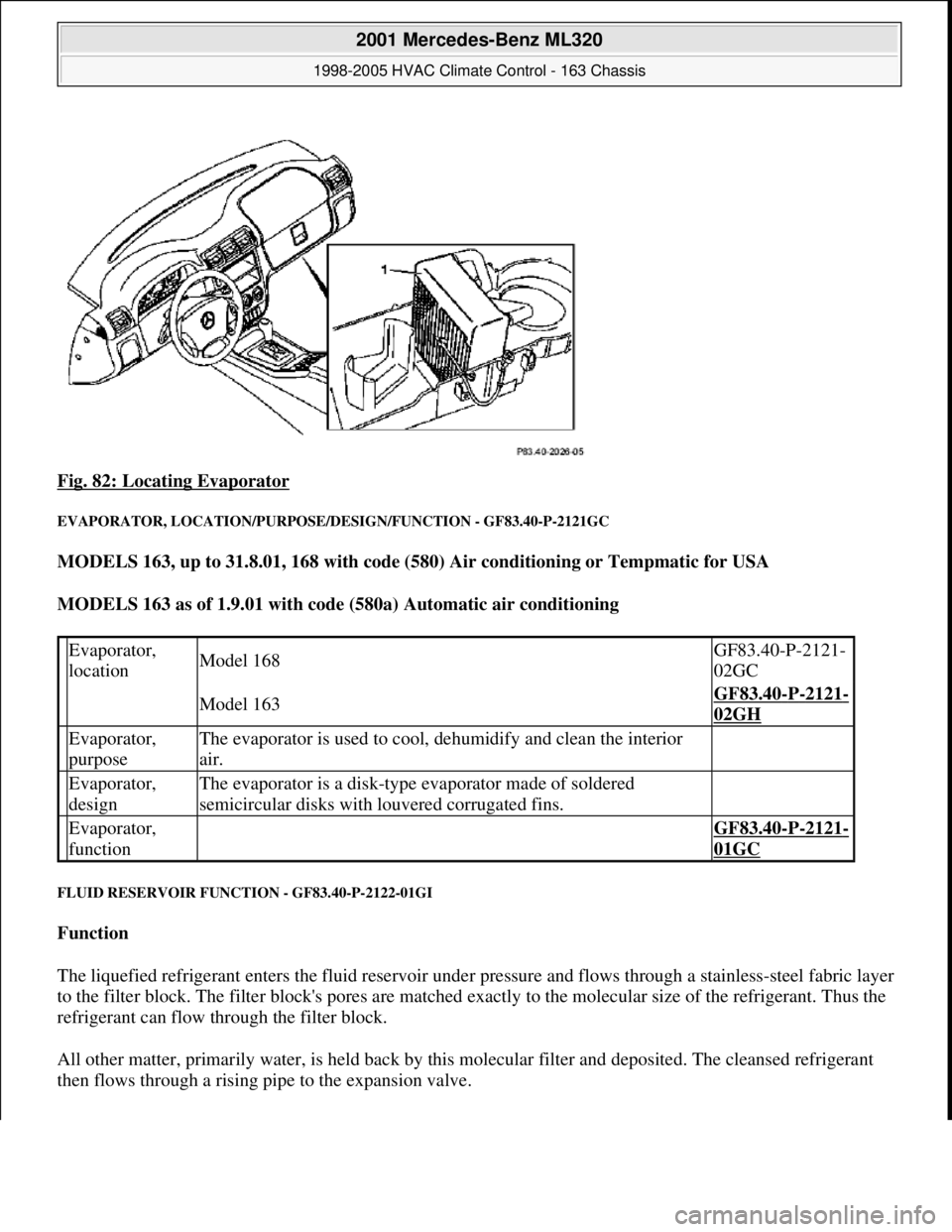
Fig. 82: Locating Evaporator
EVAPORATOR, LOCATION/PURPOSE/DESIGN/FUNCTION - GF83.40-P-2121GC
MODELS 163, up to 31.8.01, 168 with code (580) Air conditioning or Tempmatic for USA
MODELS 163 as of 1.9.01 with code (580a) Automatic air conditioning
FLUID RESERVOIR FUNCTION - GF83.40-P-2122-01GI
Function
The liquefied refrigerant enters the fluid reservoir under pressure and flows through a stainless-steel fabric layer
to the filter block. The filter block's pores are matched exactly to the molecular size of the refrigerant. Thus the
refrigerant can flow through the filter block.
All other matter, primarily water, is held back by this molecular filter and deposited. The cleansed refrigerant
then flows through a rising pipe to the expansion valve.
Evaporator,
locationModel 168GF83.40-P-2121-
02GC
Model 163GF83.40-P-2121-
02GH
Evaporator,
purposeThe evaporator is used to cool, dehumidify and clean the interior
air.
Evaporator,
designThe evaporator is a disk-type evaporator made of soldered
semicircular disks with louvered corrugated fins.
Evaporator,
function GF83.40-P-2121-
01GC
2001 Mercedes-Benz ML320
1998-2005 HVAC Climate Control - 163 Chassis
me
Saturday, October 02, 2010 3:23:16 PMPage 102 © 2006 Mitchell Repair Information Company, LLC.
Page 3372 of 4133
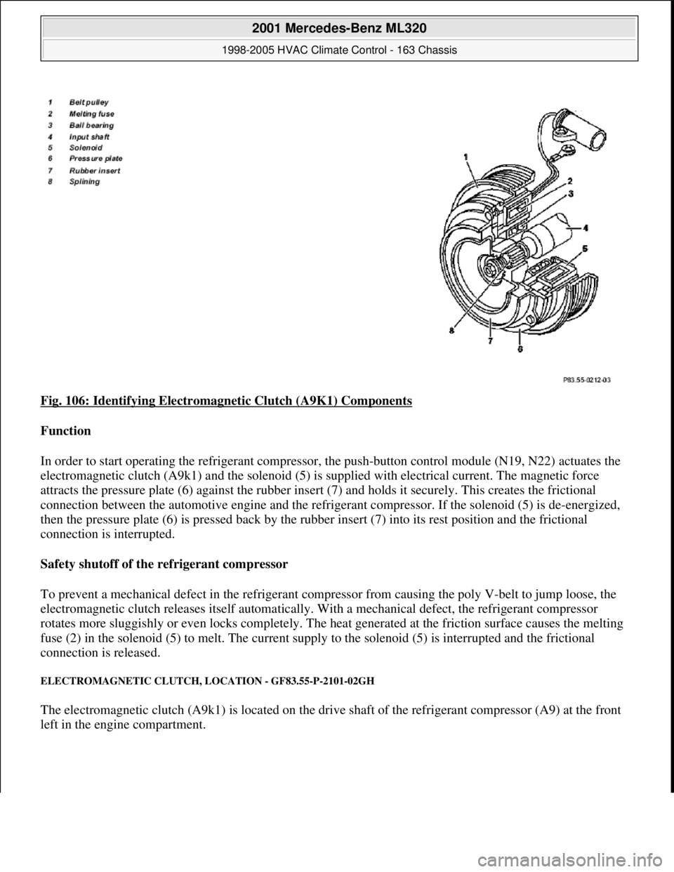
Fig. 106: Identifying Electromagnetic Clutch (A9K1) Components
Function
In order to start operating the refrigerant compressor, the push-button control module (N19, N22) actuates the
electromagnetic clutch (A9k1) and the solenoid (5) is supplied with electrical current. The magnetic force
attracts the pressure plate (6) against the rubber insert (7) and holds it securely. This creates the frictional
connection between the automotive engine and the refrigerant compressor. If the solenoid (5) is de-energized,
then the pressure plate (6) is pressed back by the rubber insert (7) into its rest position and the frictional
connection is interrupted.
Safety shutoff of the refrigerant compressor
To prevent a mechanical defect in the refrigerant compressor from causing the poly V-belt to jump loose, the
electromagnetic clutch releases itself automatically. With a mechanical defect, the refrigerant compressor
rotates more sluggishly or even locks completely. The heat generated at the friction surface causes the melting
fuse (2) in the solenoid (5) to melt. The current supply to the solenoid (5) is interrupted and the frictional
connection is released.
ELECTROMAGNETIC CLUTCH, LOCATION - GF83.55-P-2101-02GH
The electromagnetic clutch (A9k1) is located on the drive shaft of the refrigerant compressor (A9) at the front
left in the en
gine compartment.
2001 Mercedes-Benz ML320
1998-2005 HVAC Climate Control - 163 Chassis
me
Saturday, October 02, 2010 3:23:16 PMPage 128 © 2006 Mitchell Repair Information Company, LLC.
Page 3433 of 4133
Air conditioning system
Workshop equipment
REMOVE/INSTALL DEFROSTER VENT FLAP ACTUATOR MOTOR FOR WINDSHIELD - AR83.30-P-2006GH
MODEL 163.113 /154 /174 #A as of 289565, 163.113 #X as of 754620, 163.128/157/175
4evacuate
Filling
5Supplement oil for refrigerant
compressor The exact quantity determined when
drained must be used.
6Fill air conditioning system *BF83.30-P-
1001-01B
Testing
7Inspect air conditioning system for leaks
with leak detector *WE58.40-
Z-1002-20A
8
Risk of accident. Accidents may result if
the vehicle starts off unintentionally with
the engine running. Risk of injury from
bruises and burns if you hold your hand
near engine when it is started or when it
is running. Check function of air
conditioningSecure vehicle to prevent it from moving.
Wear closed and snug-fitting work clothes.
Do not grasp hot or rotating parts.
Run engine at idle speed for about 4
minutes and check all the component
functions which are of relevance for proper
operation of the air conditioning system.
AS00.00-Z-
0005-01A
NumberDesignationModel Series 163
BF83.30-P-1001-01BRefrigerantsFilling quantityg750
Specifications for Operating FluidsSheetBB00.40-P-0361-00A
WE58.40-Z-1002-20AAir conditioning leak detector
WE58.40-Z-1002-22AAir conditioning service station
2001 Mercedes-Benz ML320
1998-2005 HVAC Climate Control - 163 Chassis
me
Saturday, October 02, 2010 3:23:18 PMPage 189 © 2006 Mitchell Repair Information Company, LLC.
Page 3457 of 4133
Air conditioning system
Refrigerant compressor
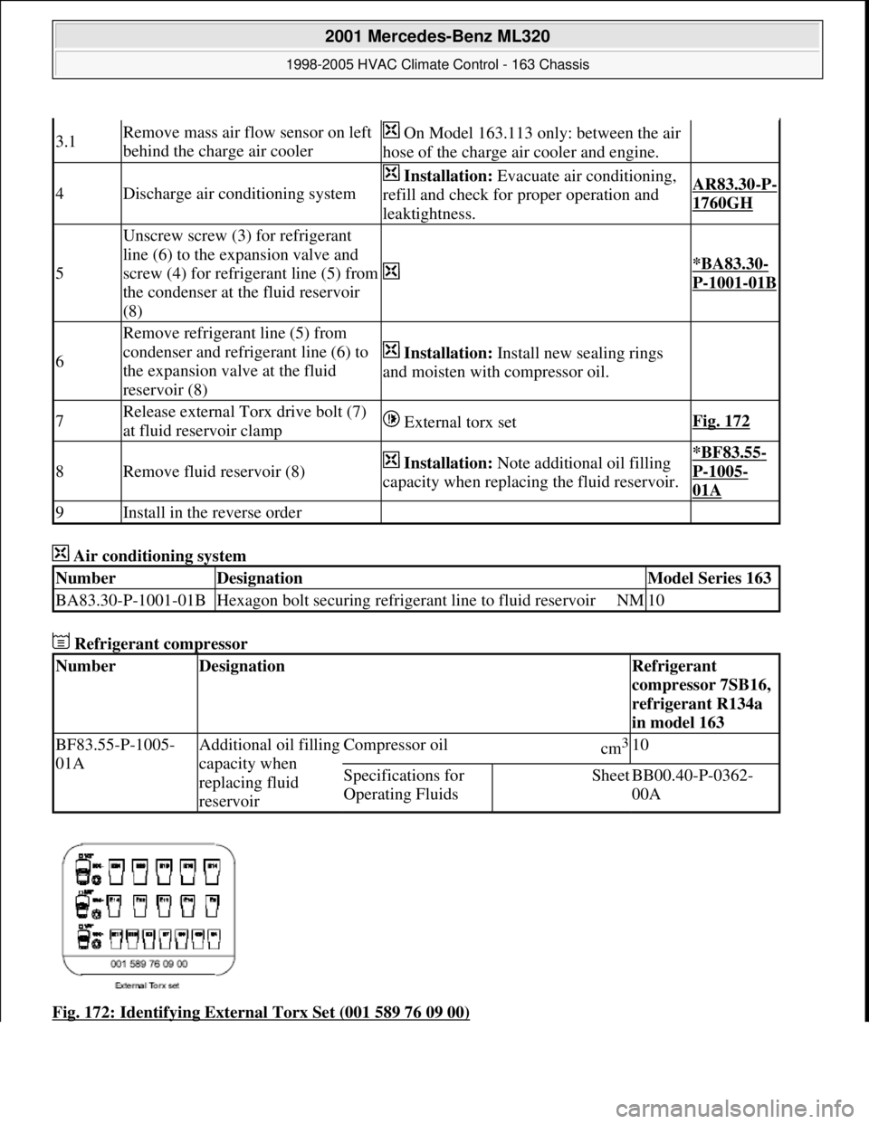
Fig. 172: Identifying External Torx Set (001 589 76 09 00)
3.1Remove mass air flow sensor on left
behind the charge air cooler On Model 163.113 only: between the air
hose of the charge air cooler and engine.
4Discharge air conditioning system
Installation: Evacuate air conditioning,
refill and check for proper operation and
leaktightness.AR83.30-P-
1760GH
5
Unscrew screw (3) for refrigerant
line (6) to the expansion valve and
screw (4) for refrigerant line (5) from
the condenser at the fluid reservoir
(8)
*BA83.30-
P-1001-01B
6
Remove refrigerant line (5) from
condenser and refrigerant line (6) to
the expansion valve at the fluid
reservoir (8)
Installation: Install new sealing rings
and moisten with compressor oil.
7Release external Torx drive bolt (7)
at fluid reservoir clamp External torx setFig. 172
8Remove fluid reservoir (8) Installation: Note additional oil filling
capacity when replacing the fluid reservoir.*BF83.55-
P-1005-
01A
9Install in the reverse order
NumberDesignationModel Series 163
BA83.30-P-1001-01BHexagon bolt securing refrigerant line to fluid reservoirNM10
NumberDesignationRefrigerant
compressor 7SB16,
refrigerant R134a
in model 163
BF83.55-P-1005-
01AAdditional oil filling
capacity when
replacing fluid
reservoirCompressor oilcm3 10
Specifications for
Operating FluidsSheetBB00.40-P-0362-
00A
2001 Mercedes-Benz ML320
1998-2005 HVAC Climate Control - 163 Chassis
me
Saturday, October 02, 2010 3:23:18 PMPage 213 © 2006 Mitchell Repair Information Company, LLC.
Page 3460 of 4133
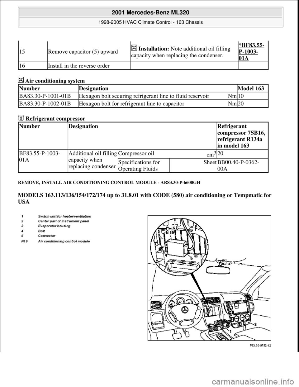
Air conditioning system
Refrigerant compressor
REMOVE, INSTALL AIR CONDITIONING CONTROL MODULE - AR83.30-P-6600GH
MODELS 163.113/136/154/172/174 up to 31.8.01 with CODE (580) air conditioning or Tempmatic for
USA
15Remove capacitor (5) upward Installation: Note additional oil filling
capacity when replacing the condenser.*BF83.55-
P-1003-
01A
16Install in the reverse order
NumberDesignationModel 163
BA83.30-P-1001-01BHexagon bolt securing refrigerant line to fluid reservoirNm10
BA83.30-P-1002-01BHexagon bolt for refrigerant line to capacitorNm20
NumberDesignationRefrigerant
compressor 7SB16,
refrigerant R134a
in model 163
BF83.55-P-1003-
01AAdditional oil filling
capacity when
replacing condenserCompressor oilcm3 20
Specifications for
Operating FluidsSheetBB00.40-P-0362-
00A
2001 Mercedes-Benz ML320
1998-2005 HVAC Climate Control - 163 Chassis
me
Saturday, October 02, 2010 3:23:18 PMPage 216 © 2006 Mitchell Repair Information Company, LLC.
Page 3473 of 4133
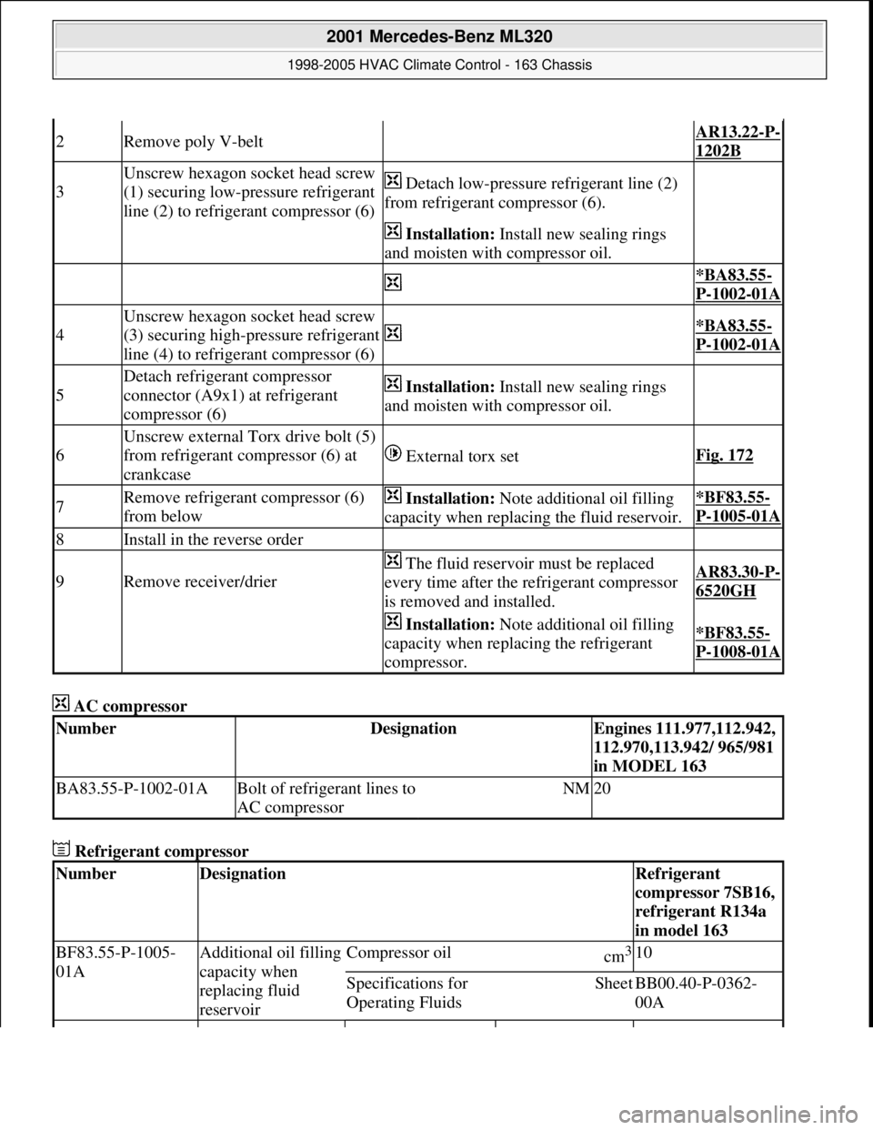
AC compressor
Refrigerant compressor
2Remove poly V-belt AR13.22-P-
1202B
3
Unscrew hexagon socket head screw
(1) securing low-pressure refrigerant
line (2) to refrigerant compressor (6) Detach low-pressure refrigerant line (2)
from refrigerant compressor (6).
Installation: Install new sealing rings
and moisten with compressor oil.
*BA83.55-
P-1002-01A
4
Unscrew hexagon socket head screw
(3) securing high-pressure refrigerant
line (4) to refrigerant compressor (6)
*BA83.55-
P-1002-01A
5
Detach refrigerant compressor
connector (A9x1) at refrigerant
compressor (6) Installation: Install new sealing rings
and moisten with compressor oil.
6
Unscrew external Torx drive bolt (5)
from refrigerant compressor (6) at
crankcase
External torx setFig. 172
7Remove refrigerant compressor (6)
from below Installation: Note additional oil filling
capacity when replacing the fluid reservoir.*BF83.55-
P-1005-01A
8Install in the reverse order
9Remove receiver/drier
The fluid reservoir must be replaced
every time after the refrigerant compressor
is removed and installed.AR83.30-P-
6520GH
Installation: Note additional oil filling
capacity when replacing the refrigerant
compressor.*BF83.55-
P-1008-01A
NumberDesignationEngines 111.977,112.942,
112.970,113.942/ 965/981
in MODEL 163
BA83.55-P-1002-01ABolt of refrigerant lines to
AC compressorNM20
NumberDesignationRefrigerant
compressor 7SB16,
refrigerant R134a
in model 163
BF83.55-P-1005-
01AAdditional oil filling
capacity when
replacing fluid
reservoirCompressor oilcm3 10
Specifications for
Operating FluidsSheetBB00.40-P-0362-
00A
2001 Mercedes-Benz ML320
1998-2005 HVAC Climate Control - 163 Chassis
me
Saturday, October 02, 2010 3:23:19 PMPage 229 © 2006 Mitchell Repair Information Company, LLC.