park MERCEDES-BENZ ML350 1997 Complete Repair Manual
[x] Cancel search | Manufacturer: MERCEDES-BENZ, Model Year: 1997, Model line: ML350, Model: MERCEDES-BENZ ML350 1997Pages: 4133, PDF Size: 88.89 MB
Page 2583 of 4133
AR07.16-P-1100MM
Remove, install fuel cooler
5.11.99
ENGINE
612.963 in MODELS 163.113
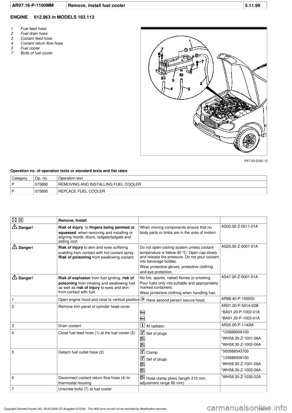
P47.00-2042-12
1
Fuel feed hose
2
Fuel drain hose
3
Coolant feed hose
4
Coolant return flow hose
5
Fuel cooler
7
Bolts of fuel cooler
Operation no. of operation texts or standard texts and flat rates
Category
Op. no.
Operation text
P
075890
REMOVING AND INSTALLING FUEL COOLER
P
075895
REPLACE FUEL COOLER
Remove, Install
Danger!
Risk of injury
to
fingers being jammed or
squeezed
when removing and installing or
aligning hoods, doors, tailgate/tailgate and
sliding roof.
When moving components ensure that no
body parts or limbs are in the area of motion.
AS00.00-Z-0011-01A
Danger!
Risk of injury
to skin and eyes suffering
scalding from contact with hot coolant spray.
Risk of poisoning
from swallowing coolant.
Do not open cooling system unless coolant
temperature is below 90 °C. Open cap slowly
and release the pressure. Do not pour coolant
into beverage bottles.
Wear protective gloves, protective clothing
and eye protection.
AS20.00-Z-0001-01A
Danger!
Risk of explosion
from fuel igniting,
risk of
poisoning
from inhaling and swallowing fuel
as well as
risk of injury
to eyes and skin
from contact with fuel.
No fire, sparks, naked flames or smoking.
Pour fuels only into suitable and appropriately
marked containers.
Wear protective clothing when handling fuel.
AS47.00-Z-0001-01A
1
Open engine hood and raise to vertical position
Have second person secure hood.
AR88.40-P-1000GI
2
Remove trim panel of cylinder head cover
AR01.20-P-5014-02B
*BA01.20-P-1002-01A
*BA01.20-P-1003-01A
3
Drain coolant
At radiator.
AR20.00-P-1142M
4
Close fuel feed hose (1) at the fuel cooler (5)
Set of plugs
*129589009100
*WH58.30-Z-1001-06A
*WH58.30-Z-1002-06A
5
Detach fuel outlet hose (2)
Clamp
*000589543700
Set of plugs
*129589009100
*WH58.30-Z-1001-06A
*WH58.30-Z-1002-06A
6
Disconnect coolant return flow hose (4) to
thermostat housing
Hose clamp pliers (length 210 mm;
adjustment range 80 mm)
*WH58.30-Z-1026-02A
7
Unscrew bolts (7) at fuel cooler
Copyright DaimlerChrysler AG 28.05.2006 CD-Ausgabe G/10/04 . This WIS print-out will not be recorde
d by Modification services.
Page 1
Page 2589 of 4133
AP47.20-P-0780BB
Replace fuel filter
2.3.99
ENGINE
611.960 in MODEL 202.133 /134 /193 /194
ENGINE
611.961 in MODEL 210.006 /007 /206 /606
ENGINE
612.961 in MODEL 210.016 /216 /616
ENGINE
612.963 in MODEL 163.113
ENGINE
613.961 in MODEL 210.026 /226
ENGINE
613.960 in MODEL 220.026 /126
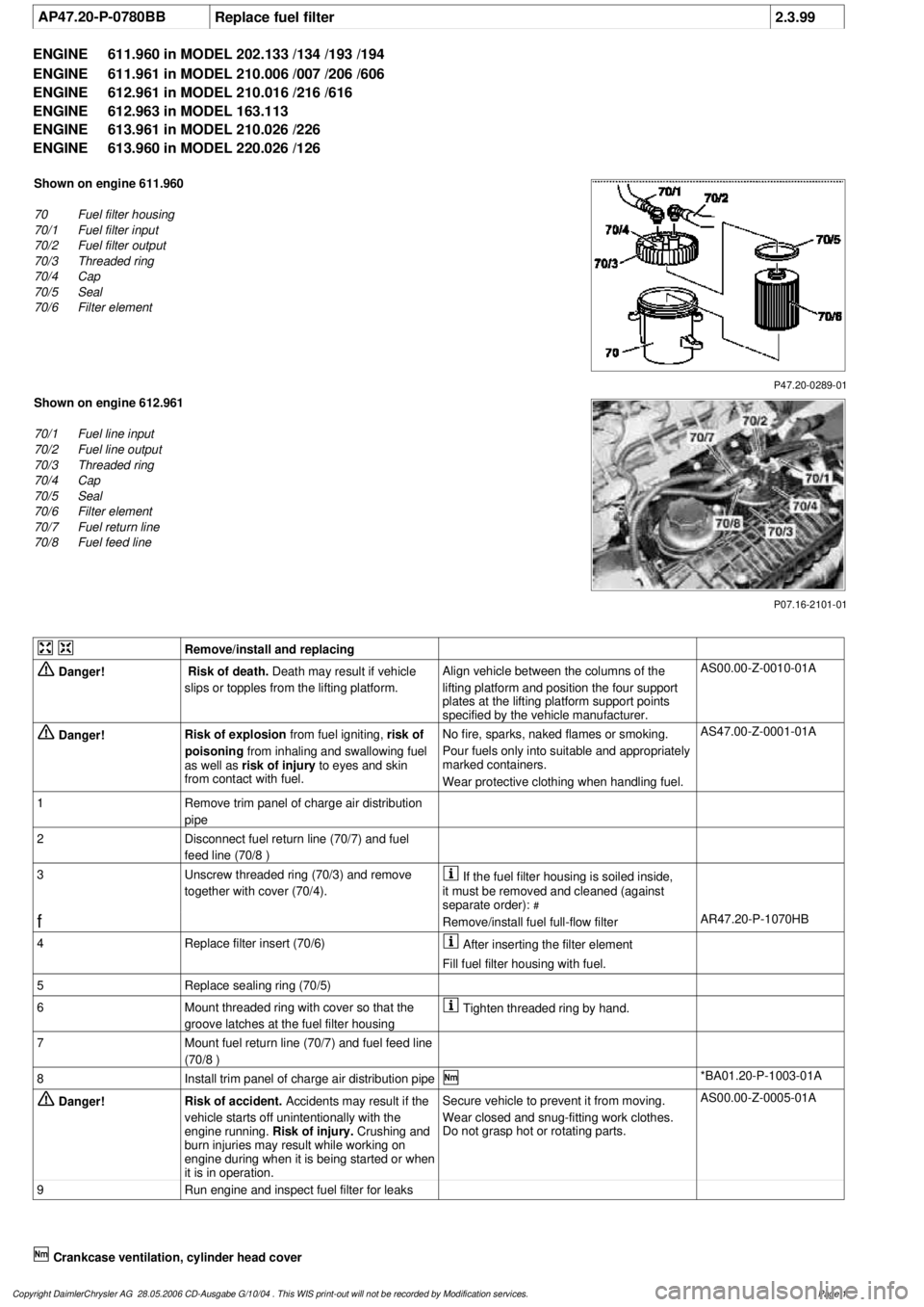
P47.20-0289-01
Shown on engine 611.960
70
Fuel filter housing
70/1
Fuel filter input
70/2
Fuel filter output
70/3
Threaded ring
70/4
Cap
70/5
Seal
70/6
Filter element
P07.16-2101-01
Shown on engine 612.961
70/1
Fuel line input
70/2
Fuel line output
70/3
Threaded ring
70/4
Cap
70/5
Seal
70/6
Filter element
70/7
Fuel return line
70/8
Fuel feed line
Remove/install and replacing
Danger!
Risk of death.
Death may result if vehicle
slips or topples from the lifting platform.
Align vehicle between the columns of the
lifting platform and position the four support
plates
at the lifting platform support points
specified by the vehicle manufacturer.
AS00.00-Z-0010-01A
Danger!
Risk of explosion
from fuel igniting,
risk of
poisoning
from inhaling and swallowing fuel
as well as
risk of injury
to eyes and skin
from contact with fuel.
No fire, sparks, naked flames or smoking.
Pour fuels only into suitable and appropriately
marked containers.
Wear protective clothing when handling fuel.
AS47.00-Z-0001-01A
1
Remove trim panel of charge air distribution
pipe
2
Disconnect fuel return line (70/7) and fuel
feed line (70/8 )
3
Unscrew threaded ring (70/3) and remove
together with cover (70/4).
If the fuel filter housing is soiled inside,
it must be removed and cleaned (against
separate order):
#
f
Remove/install fuel full-flow filter
AR47.20-P-1070HB
4
Replace filter insert (70/6)
After inserting the filter element
Fill fuel filter housing with fuel.
5
Replace sealing ring (70/5)
6
Mount threaded ring with cover so that the
groove latches at the fuel filter housing
Tighten threaded ring by hand.
7
Mount fuel return line (70/7) and fuel feed line
(70/8 )
8
Install trim panel of charge air distribution pipe
*BA01.20-P-1003-01A
Danger!
Risk of accident.
Accidents may result if the
vehicle starts off unintentionally with the
engine running.
Risk of injury.
Crushing and
burn injuries may result while working on
engine during when it is being started or when
it is in operation.
Secure vehicle to prevent it from moving.
Wear closed and snug-fitting work clothes.
Do not grasp hot or rotating parts.
AS00.00-Z-0005-01A
9
Run engine and inspect fuel filter for leaks
Crankcase ventilation, cylinder head cover
Copyright DaimlerChrysler AG 28.05.2006 CD-Ausgabe G/10/04 . This WIS print-out will not be recorde
d by Modification services.
Page 1
Page 2593 of 4133
AR47.20-P-1070HBRemove/install fuel full-flow filter
21.11.97
ENGINE
611.960 /961 /962, 612.961 /963, 613.960 /961
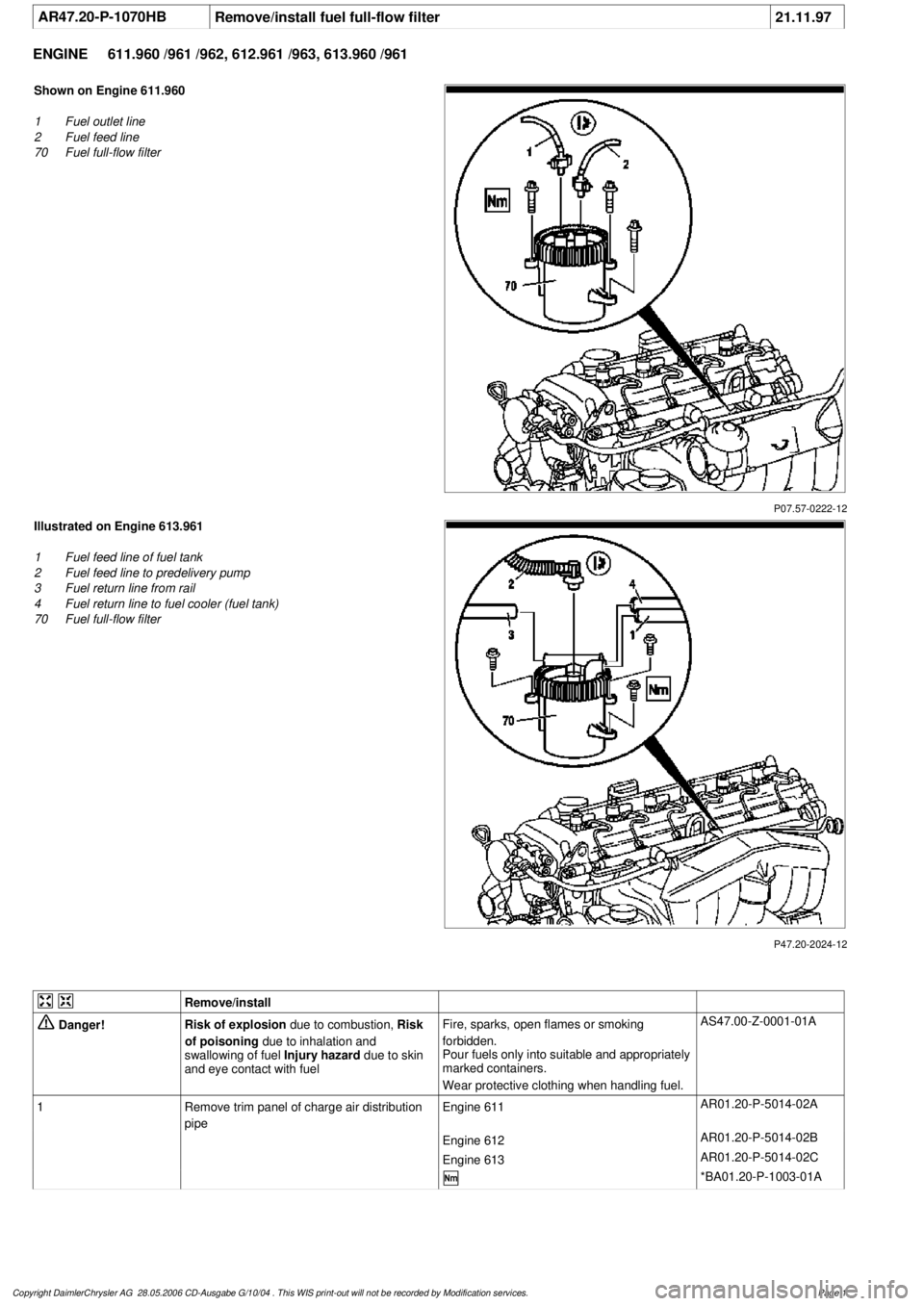
P07.57-0222-12
Shown on Engine 611.960
1
Fuel outlet line
2
Fuel feed line
70
Fuel full-flow filter
P47.20-2024-12
Illustrated on Engine 613.961
1
Fuel feed line of fuel tank
2
Fuel feed line to predelivery pump
3
Fuel return line from rail
4
Fuel return line to fuel cooler (fuel tank)
70
Fuel full-flow filter
Remove/install
Danger!
Risk of explosion
due to combustion,
Risk
of poisoning
due to inhalation and
swallowing of fuel
Injury hazard
due to skin
and eye contact with fuel
Fire, sparks, open flames or smoking
forbidden.
Pour fuels only into suitable and appropriately
marked containers.
Wear protective clothing when handling fuel.
AS47.00-Z-0001-01A
1
Remove trim panel of charge air distribution
pipe
Engine 611
AR01.20-P-5014-02A
Engine 612
AR01.20-P-5014-02B
Engine 613
AR01.20-P-5014-02C
*BA01.20-P-1003-01A
Copyright DaimlerChrysler AG 28.05.2006 CD-Ausgabe G/10/04 . This WIS print-out will not be recorde
d by Modification services.
Page 1
Page 2596 of 4133
AR47.10-P-7000GI
Remove/install fuel level sensor
21.2.01
MODEL
163.113 with ENGINE 612.963
MODEL
163.128 with ENGINE 628.963
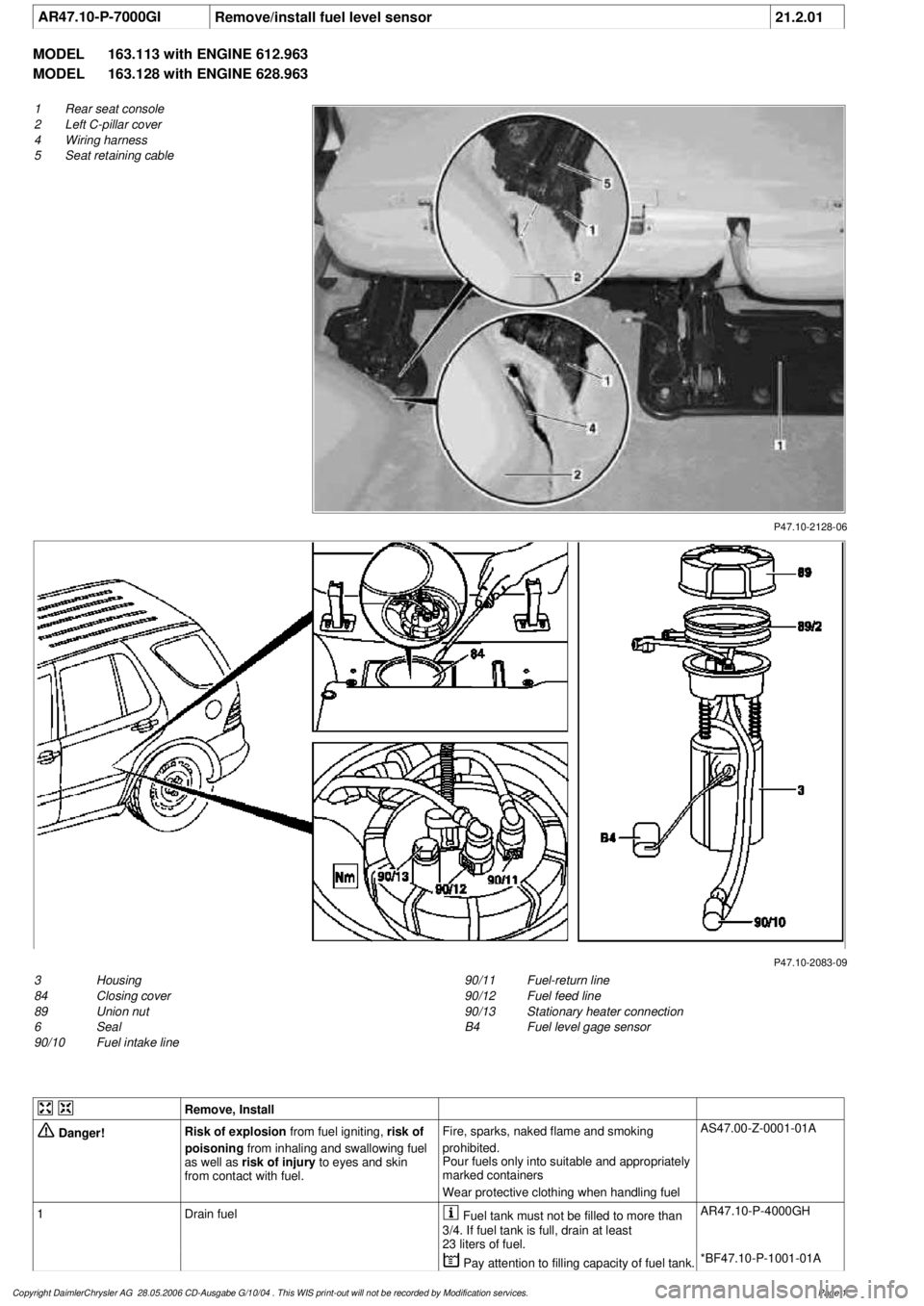
P47.10-2128-06
1
Rear seat console
2
Left C-pillar cover
4
Wiring harness
5
Seat retaining cable
P47.10-2083-09
3
Housing
84
Closing cover
89
Union nut
6
Seal
90/10
Fuel intake line
90/11
Fuel-return line
90/12
Fuel feed line
90/13
Stationary heater connection
B4
Fuel level gage sensor
Remove, Install
Danger!
Risk of explosion
from fuel igniting,
risk of
poisoning
from inhaling and swallowing fuel
as well as
risk of injury
to eyes and skin
from contact with fuel.
Fire, sparks, naked flame and smoking
prohibited.
Pour fuels only into suitable and appropriately
marked containers
Wear protective clothing when handling fuel
AS47.00-Z-0001-01A
1
Drain fuel
Fuel tank must not be filled to more than
3/4. If fuel tank is full, drain at least
23 liters of fuel.
AR47.10-P-4000GH
Pay attention to filling capacity of fuel tank.
*BF47.10-P-1001-01A
Copyright DaimlerChrysler AG 28.05.2006 CD-Ausgabe G/10/04 . This WIS print-out will not be recorde
d by Modification services.
Page 1
Page 2600 of 4133
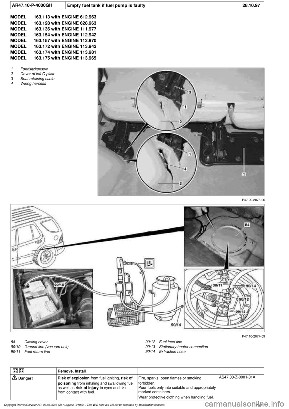
AR47.10-P-4000GH
Empty fuel tank if fuel pump is faulty
28.10.97
MODEL
163.113 with ENGINE 612.963
MODEL
163.128 with ENGINE 628.963
MODEL
163.136 with ENGINE 111.977
MODEL
163.154 with ENGINE 112.942
MODEL
163.157 with ENGINE 112.970
MODEL
163.172 with ENGINE 113.942
MODEL
163.174 with ENGINE 113.981
MODEL
163.175 with ENGINE 113.965
P47.20-2076-06
1
Fondsitzkonsole
2
Cover of left C-pillar
3
Seat retaining cable
4
Wiring harness
P47.10-2077-09
84
Closing cover
90/10
Ground line (vacuum unit)
90/11
Fuel return line
90/12
Fuel feed line
90/13
Stationary heater connection
90/14
Extraction hose
Remove, Install
Danger!
Risk of explosion
from fuel igniting,
risk of
poisoning
from inhaling and swallowing fuel
as well as
risk of injury
to eyes and skin
from contact with fuel.
Fire, sparks, open flames or smoking
forbidden.
Pour fuels only into suitable and appropriately
marked containers.
Wear protective clothing when handling fuel.
AS47.00-Z-0001-01A
Copyright DaimlerChrysler AG 28.05.2006 CD-Ausgabe G/10/04 . This WIS print-out will not be recorde
d by Modification services.
Page 1
Page 2606 of 4133
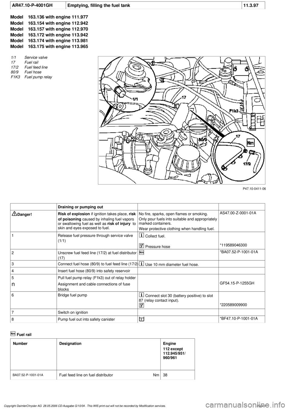
AR47.10-P-4001GH
Emptying, filling the fuel tank
11.3.97
Model
163.136 with engine 111.977
Model
163.154 with engine 112.942
Model
163.157 with engine 112.970
Model
163.172 with engine 113.942
Model
163.174 with engine 113.981
Model
163.175 with engine 113.965
P47.10-0411-06
1/1
Service valve
17
Fuel rail
17/2
Fuel feed line
80/9
Fuel hose
F1K3
Fuel pump relay
Draining or pumping out
Danger!
Risk of explosion
if ignition takes place,
risk
of poisoning
caused by inhaling fuel vapors
or swallowing fuel as well as
risk of injury
to
skin and eyes exposed to fuel.
No fire, sparks, open flames or smoking.
Only pour fuels into suitable and appropriately
marked containers.
Wear protective clothing when handling fuel.
AS47.00-Z-0001-01A
1
Release fuel pressure through service valve
(1/1)
Collect fuel.
Pressure hose
*119589046300
2
Unscrew fuel feed line (17/2) at fuel distributor
(17)
*BA07.52-P-1001-01A
3
Connect fuel hose (80/9) to fuel feed line (17/2)
Use 10 mm diameter fuel hose.
4
Insert fuel hose (80/9) into safety reservoir
5
Pull fuel pump relay (F1k3) out of relay holder
n
Assignment and cable connections of fuse
blocks
GF54.15-P-1255GH
6
Bridge fuel pump
Connect slot 30 (battery positive) to slot
87 (relay contact input).
*220589009900
7
Switch on ignition
8
Pump fuel out into safety canister
*BF47.10-P-1001-01A
Fuel rail
Number
Designation
Engine
112 except
112.945/951/
960/961
BA07.52-P-1001-01A
Fuel feed line on fuel distributor
Nm
38
Copyright DaimlerChrysler AG 28.05.2006 CD-Ausgabe G/10/04 . This WIS print-out will not be recorde
d by Modification services.
Page 1
Page 2609 of 4133

Remove, Install
Danger!
Risk of explosion
from fuel igniting,
risk of
poisoning
from inhaling and swallowing fuel
as well as
risk of injury
to eyes and skin
from contact with fuel.
Fire, sparks, open flames or smoking
forbidden.
Pour fuels only into suitable and appropriately
marked containers.
Wear protective clothing when handling fuel.
AS47.00-Z-0001-01A
1
Drain fuel tank
Via fuel pump. NOT for model 163.113/128.
AR47.10-P-4001GH
If fuel pump faulty, and model 163.113/128.
AR47.10-P-4000GH
*BF47.10-P-1001-01A
2
Unscrew filler cap (2) and detach from filler
cap attachment (4)
3.1
Remove left seat of 3rd seat row
If installed. See owner's manual
4
Unclip cover of left-hand side panel (1)
5.1
Detach fuel lines of expansion reservoir and
separate from filler neck
As of VIN A289565. NOT for model
163.113/128.
6
Detach fuel filler neck from guide funnel
Installation:
Check O-ring and replace if
necessary. Ensure that the bayonet-lock
remains above
the pressure sensor.
Ensure it is correctly located when installed.
Open bayonet lock (3) to do this.
7
Pull filler neck through toward interior
Screw on cap again in order to avoid fuel
flowing out.
8.1
Remove fuel tank pressure sensor (B4/3)
Only USA version
AR47.10-P-8022GH
9.1
Detach bolted connection of fuel tank filler
neck/ground (X36/4) from filler neck
NOT for model 163.113/128.
10.1
Cut cable strap for retaining clips of fuel lines
at filler neck and remove retaining clips
As of VIN A289565. NOT for model
163.113/128.
Danger!
Risk of fatal accident
from vehicle slipping
or toppling off the lift platform
Align vehicle between the columns of lifting
platform and position the four support plates
below the support strongpoints specified by
the vehicle manufacturer.
AS00.00-Z-0010-01A
11
Place the vehicle on lifting platform
AR00.60-P-1000GH
12
Separate rubber seal (5) from underside of
vehicle and remove filler neck from interior
Do not damage fuel lines at filler neck.
13
Remove left rear wheel
e
Removing and installing wheels, rotating if
necessary
AP40.10-P-4050GH
14
Remove spare wheel and spare wheel carrier
complete
NOT in the case of spare wheel
holder/spare wheel, code 849.
15
Cut a large safety cable strap for filler neck at
bracket on longitudinal frame member
16
Remove bracket from longitudinal frame
member
17
Disconnect connection for regeneration (77/2)
and fresh air connection (77/4) on activated
charcoal canister (77)
Installation
: Connect up lines as per
connection diagram:
#
Engine 111
AR47.30-P-8212-01GJ
Engines 112, 113
AR47.30-P-8212-01GI
Engines 112, 113 version
I
AR47.30-P-8212-01GH
Charcoal canister and fuel tank form a
single unit.
NOT for model 163.113/128.
18
Detach vent hose
At rear differential to rear of activated
charcoal reservoir.
19
Remove rear exhaust system heat shield.
Do not damage boot at rear axle shaft.
20
Disconnect rear propeller shaft at differential
Installation:
Install new self-locking bolts.
Tie up propeller shaft e.g. using welding
wire
Heat bolts with hot air fan to facilitate
removing. Mark propeller shaft and differential
gear flange for correct installed position.
*BA41.10-P-1002-01C
Copyright DaimlerChrysler AG 28.05.2006 CD-Ausgabe G/10/04 . This WIS print-out will not be recorde
d by Modification services.
Page 2
Page 2612 of 4133
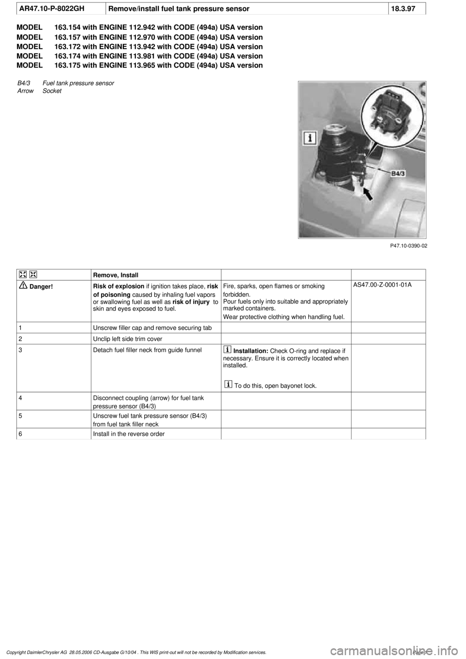
AR47.10-P-8022GH
Remove/install fuel tank pressure sensor
18.3.97
MODEL
163.154 with ENGINE 112.942 with CODE (494a) USA version
MODEL
163.157 with ENGINE 112.970 with CODE (494a) USA version
MODEL
163.172 with ENGINE 113.942 with CODE (494a) USA version
MODEL
163.174 with ENGINE 113.981 with CODE (494a) USA version
MODEL
163.175 with ENGINE 113.965 with CODE (494a) USA version
P47.10-0390-02
B4/3Fuel tank pressure sensor
Arrow
Socket
Remove, Install
Danger!
Risk of explosion
if ignition takes place,
risk
of poisoning
caused by inhaling fuel vapors
or swallowing fuel as well as
risk of injury
to
skin and eyes exposed to fuel.
Fire, sparks, open flames or smoking
forbidden.
Pour fuels only into suitable and appropriately
marked containers.
Wear protective clothing when handling fuel.
AS47.00-Z-0001-01A
1
Unscrew filler cap and remove securing tab
2
Unclip left side trim cover
3
Detach fuel filler neck from guide funnel
Installation:
Check O-ring and replace if
necessary. Ensure it is correctly located when
installed.
To do this, open bayonet lock.
4
Disconnect coupling (arrow) for fuel tank
pressure sensor (B4/3)
5
Unscrew fuel tank pressure sensor (B4/3)
from fuel tank filler neck
6
Install in the reverse order
Copyright DaimlerChrysler AG 28.05.2006 CD-Ausgabe G/10/04 . This WIS print-out will not be recorde
d by Modification services.
Page 1
Page 2613 of 4133
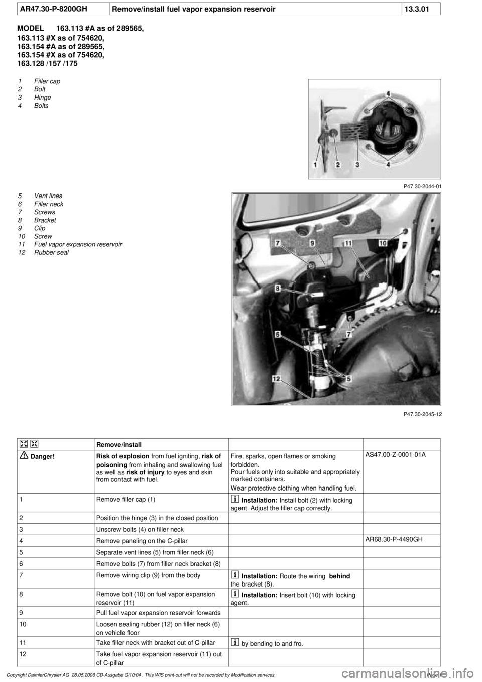
AR47.30-P-8200GH
Remove/install fuel vapor expansion reservoir
13.3.01
MODEL
163.113 #A as of 289565,
163.113 #X as of 754620,
163.154 #A as of 289565,
163.154 #X as of 754620,
163.128 /157 /175
P47.30-2044-01
1
Filler cap
2
Bolt
3
Hinge
4
Bolts
P47.30-2045-12
5
Vent lines
6
Filler neck
7
Screws
8
Bracket
9
Clip
10
Screw
11
Fuel vapor expansion reservoir
12
Rubber seal
Remove/install
Danger!
Risk of explosion
from fuel igniting,
risk of
poisoning
from inhaling and swallowing fuel
as well as
risk of injury
to eyes and skin
from contact with fuel.
Fire, sparks, open flames or smoking
forbidden.
Pour fuels only into suitable and appropriately
marked containers.
Wear protective clothing when handling fuel.
AS47.00-Z-0001-01A
1
Remove filler cap (1)
Installation:
Install bolt (2) with locking
agent. Adjust the filler cap correctly.
2
Position the hinge (3) in the closed position
3
Unscrew bolts (4) on filler neck
4
Remove paneling on the C-pillar
AR68.30-P-4490GH
5
Separate vent lines (5) from filler neck (6)
6
Remove bolts (7) from filler neck bracket (8)
7
Remove wiring clip (9) from the body
Installation:
Route the wiring
behind
the bracket (8).
8
Remove bolt (10) on fuel vapor expansion
reservoir (11)
Installation:
Insert bolt (10) with locking
agent.
9
Pull fuel vapor expansion reservoir forwards
10
Loosen sealing rubber (12) on filler neck (6)
on vehicle floor
11
Take filler neck with bracket out of C-pillar
by bending to and fro.
12
Take fuel vapor expansion reservoir (11) out
of C-pillar
Copyright DaimlerChrysler AG 28.05.2006 CD-Ausgabe G/10/04 . This WIS print-out will not be recorde
d by Modification services.
Page 1
Page 2646 of 4133
1998-2005 GENINFO
Overall vehicle - 163 Chassis
GENERAL INFORMATION
NOTES ON SELF-LOCKING NUTS AND BOLTS - AH00.00-N-0001-01A
All models
Important repair information
Bolts with locking splines, micro-encapsulated bolts and self-locking nuts must always be replaced after
being used once.
There is an increased risk of injury when unscrewing micro-encapsulated bolts due to the sudden breakaway
torque.
Before new micro-encapsulated bolts are screwed in, the mating thread must be re-cut in order to remove all the
residue of the old bolt locking compound.
MEASURES FOR PREVENTING DAMAGE TO VEHICLES OR COMPONENTS WHEN PERFORMING ARC WELDING
WORK - AH00.00-N-0005-01A
All models
The following measures must be taken before welding in order to prevent damage to various vehicle
components:
1 Have fire extinguishers at the ready.
2 The negative terminal of the battery must be disconnected and covered up.
3 In vehicle with airbags the red, 12-pin test connection/plug-in connection must be disconnected no
sooner than two seconds after the battery has been disconnected (risk of unwanted activation).
6 Attach protective shields to prevent flying sparks and radiated heat in endangered areas.
7 Do not touch electronics housings or electrical cables with the welding electrode or the welder's ground
connection.
8 If two parts are being welded together, both parts must be attached to the welder's negative clamp.
9 Make direct connection between the electrical welder's ground connection and the part being welded.
Ensure that there are no electrically insulating parts between the ground connection and the welding
point.
10 Protect or remove any parts that are sensitive to heat such as plastic cables.
11 Remove electrical cables that are laid in cavities and/or pipelines, covered containers and electrical
components from the danger area before welding.
12 If possible, the points where the welded part is being attached to the vehicle and the ground terminal is
attached to the electrical welder must be bare; remove all traces of paint, corrosion, oil, grease and
2004 Mercedes-Benz ML350
1998-2005 GENINFO Overall vehicle - 163 Chassis
2004 Mercedes-Benz ML350
1998-2005 GENINFO Overall vehicle - 163 Chassis
me
Saturday, October 02, 2010 3:47:43 PMPage 1 © 2006 Mitchell Repair Information Company, LLC.
me
Saturday, October 02, 2010 3:48:01 PMPage 1 © 2006 Mitchell Repair Information Company, LLC.