park MERCEDES-BENZ ML350 1997 Complete Repair Manual
[x] Cancel search | Manufacturer: MERCEDES-BENZ, Model Year: 1997, Model line: ML350, Model: MERCEDES-BENZ ML350 1997Pages: 4133, PDF Size: 88.89 MB
Page 2419 of 4133
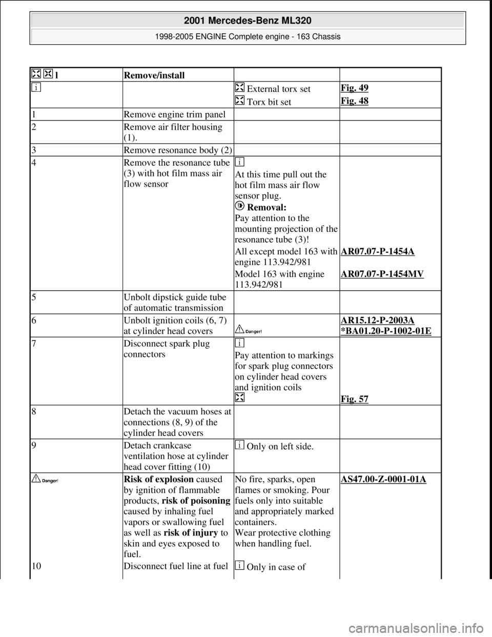
lRemove/install
External torx setFig. 49
Torx bit setFig. 48
1Remove engine trim panel
2Remove air filter housing
(1).
3Remove resonance body (2)
4Remove the resonance tube
(3) with hot film mass air
flow sensor
At this time pull out the
hot film mass air flow
sensor plug.
Removal:
Pay attention to the
mounting projection of the
resonance tube (3)!
All except model 163 with
engine 113.942/981AR07.07-P-1454A
Model 163 with engine
113.942/981AR07.07-P-1454MV
5Unbolt dipstick guide tube
of automatic transmission
6Unbolt ignition coils (6, 7)
at cylinder head covers
AR15.12-P-2003A
*BA01.20
-P-1002-01E
7Disconnect spark plug
connectors
Pay attention to markings
for spark plug connectors
on cylinder head covers
and ignition coils
Fig. 57
8Detach the vacuum hoses at
connections (8, 9) of the
cylinder head covers
9Detach crankcase
ventilation hose at cylinder
head cover fitting (10) Only on left side.
Risk of explosion caused
by ignition of flammable
products, risk of poisoning
caused by inhaling fuel
vapors or swallowing fuel
as well as risk of injury to
skin and eyes exposed to
fuel.No fire, sparks, open
flames or smoking. Pour
fuels only into suitable
and appropriately marked
containers.
Wear protective clothing
when handling fuel.AS47.00-Z-0001-01A
10Disconnect fuel line at fuel Only in case of
2001 Mercedes-Benz ML320
1998-2005 ENGINE Complete engine - 163 Chassis
me
Saturday, October 02, 2010 3:17:56 PMPage 63 © 2006 Mitchell Repair Information Company, LLC.
Page 2423 of 4133
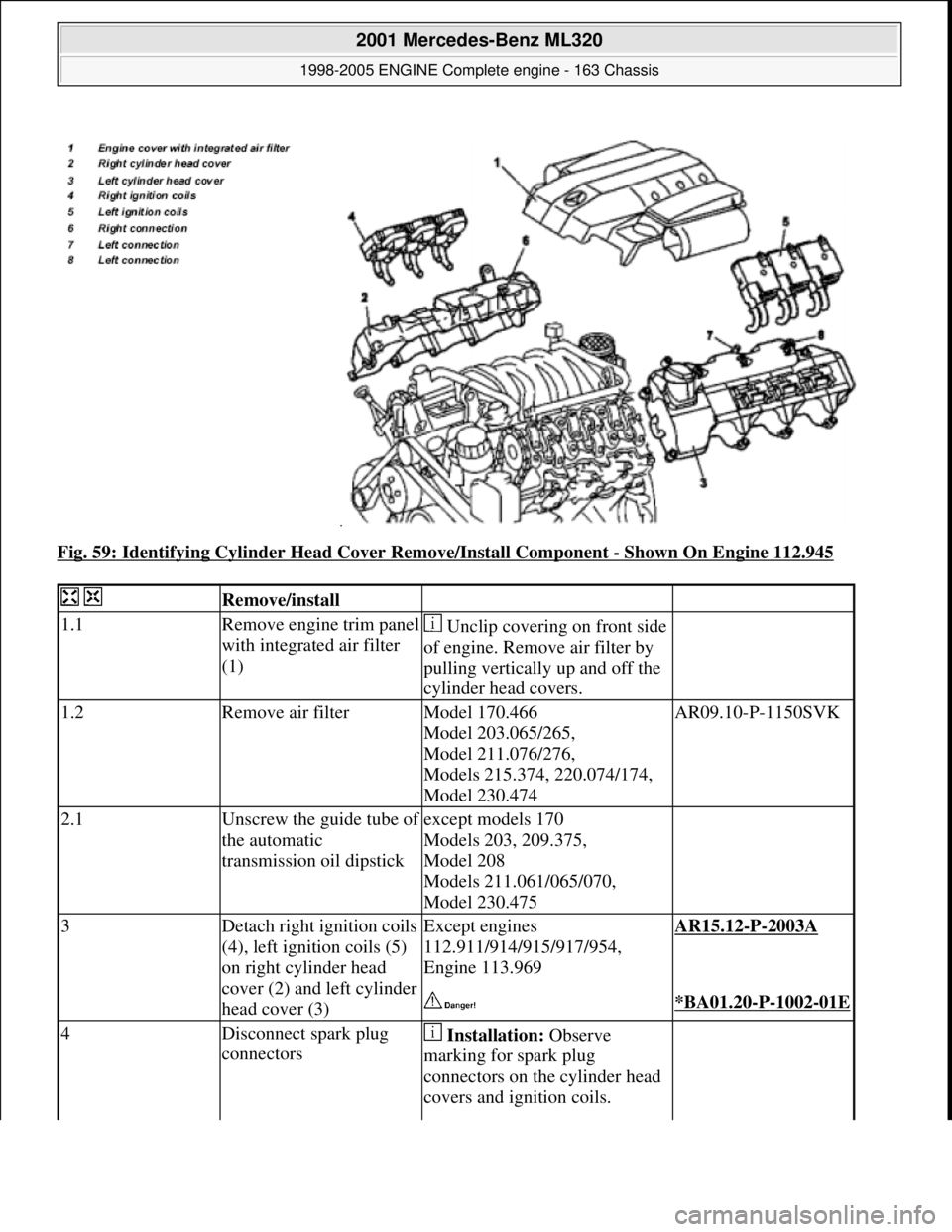
Fig. 59: Identifying Cylinder Head Cover Remove/Install Component - Shown On Engine 112.945
Remove/install
1.1Remove engine trim panel
with integrated air filter
(1) Unclip covering on front side
of engine. Remove air filter by
pulling vertically up and off the
cylinder head covers.
1.2Remove air filterModel 170.466
Model 203.065/265,
Model 211.076/276,
Models 215.374, 220.074/174,
Model 230.474AR09.10-P-1150SVK
2.1Unscrew the guide tube of
the automatic
transmission oil dipstickexcept models 170
Models 203, 209.375,
Model 208
Models 211.061/065/070,
Model 230.475
3Detach right ignition coils
(4), left ignition coils (5)
on right cylinder head
cover (2) and left cylinder
head cover (3)Except engines
112.911/914/915/917/954,
Engine 113.969AR15.12-P-2003A
*BA01.20-P-1002-01E
4Disconnect spark plug
connectors Installation: Observe
marking for spark plug
connectors on the cylinder head
covers and ignition coils.
2001 Mercedes-Benz ML320
1998-2005 ENGINE Complete engine - 163 Chassis
me
Saturday, October 02, 2010 3:17:56 PMPage 67 © 2006 Mitchell Repair Information Company, LLC.
Page 2424 of 4133
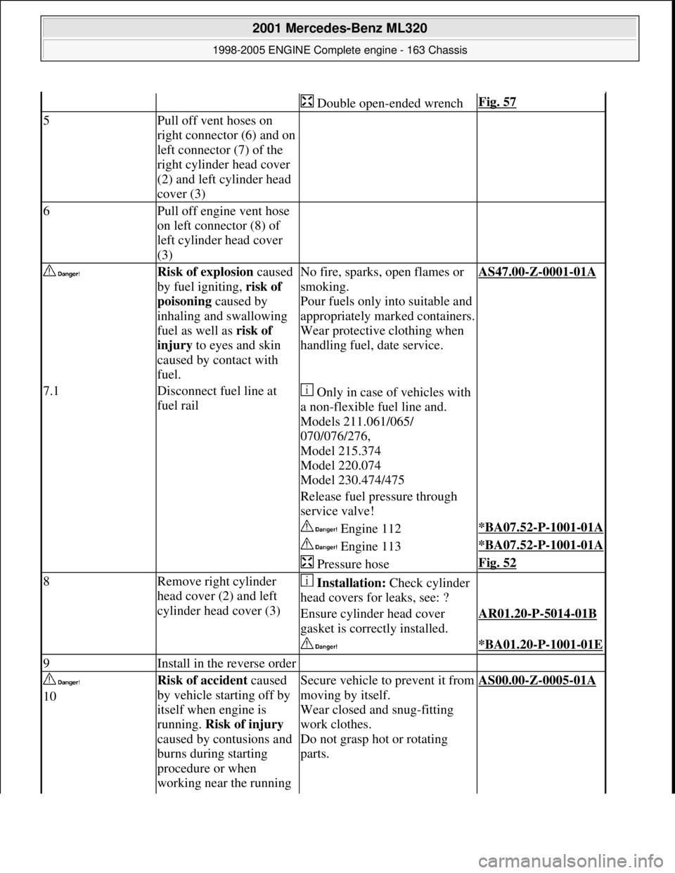
Double open-ended wrenchFig. 57
5Pull off vent hoses on
right connector (6) and on
left connector (7) of the
right cylinder head cover
(2) and left cylinder head
cover (3)
6Pull off engine vent hose
on left connector (8) of
left cylinder head cover
(3)
Risk of explosion caused
by fuel igniting, risk of
poisoning caused by
inhaling and swallowing
fuel as well as risk of
injury to eyes and skin
caused by contact with
fuel.No fire, sparks, open flames or
smoking.
Pour fuels only into suitable and
appropriately marked containers.
Wear protective clothing when
handling fuel, date service.AS47.00-Z-0001-01A
7.1Disconnect fuel line at
fuel rail Only in case of vehicles with
a non-flexible fuel line and.
Models 211.061/065/
070/076/276,
Model 215.374
Model 220.074
Model 230.474/475
Release fuel pr essure through
service valve!
Engine 112*BA07.52-P-1001-01A
Engine 113*BA07.52-P-1001-01A
Pressure hoseFig. 52
8Remove right cylinder
head cover (2) and left
cylinder head cover (3) Installation: Check cylinder
head covers for leaks, see: ?
Ensure cylinder head cover
gasket is correctly installed.AR01.20-P-5014-01B
*BA01.20-P-1001-01E
9Install in the reverse order
10Risk of accident caused
by vehicle starting off by
itself when engine is
running. Risk of injury
caused by contusions and
burns during starting
procedure or when
working near the running Secure vehicle to prevent it from
moving by itself.
Wear closed and snug-fitting
work clothes.
Do not grasp hot or rotating
parts.AS00.00-Z-0005-01A
2001 Mercedes-Benz ML320
1998-2005 ENGINE Complete engine - 163 Chassis
me
Saturday, October 02, 2010 3:17:56 PMPage 68 © 2006 Mitchell Repair Information Company, LLC.
Page 2426 of 4133
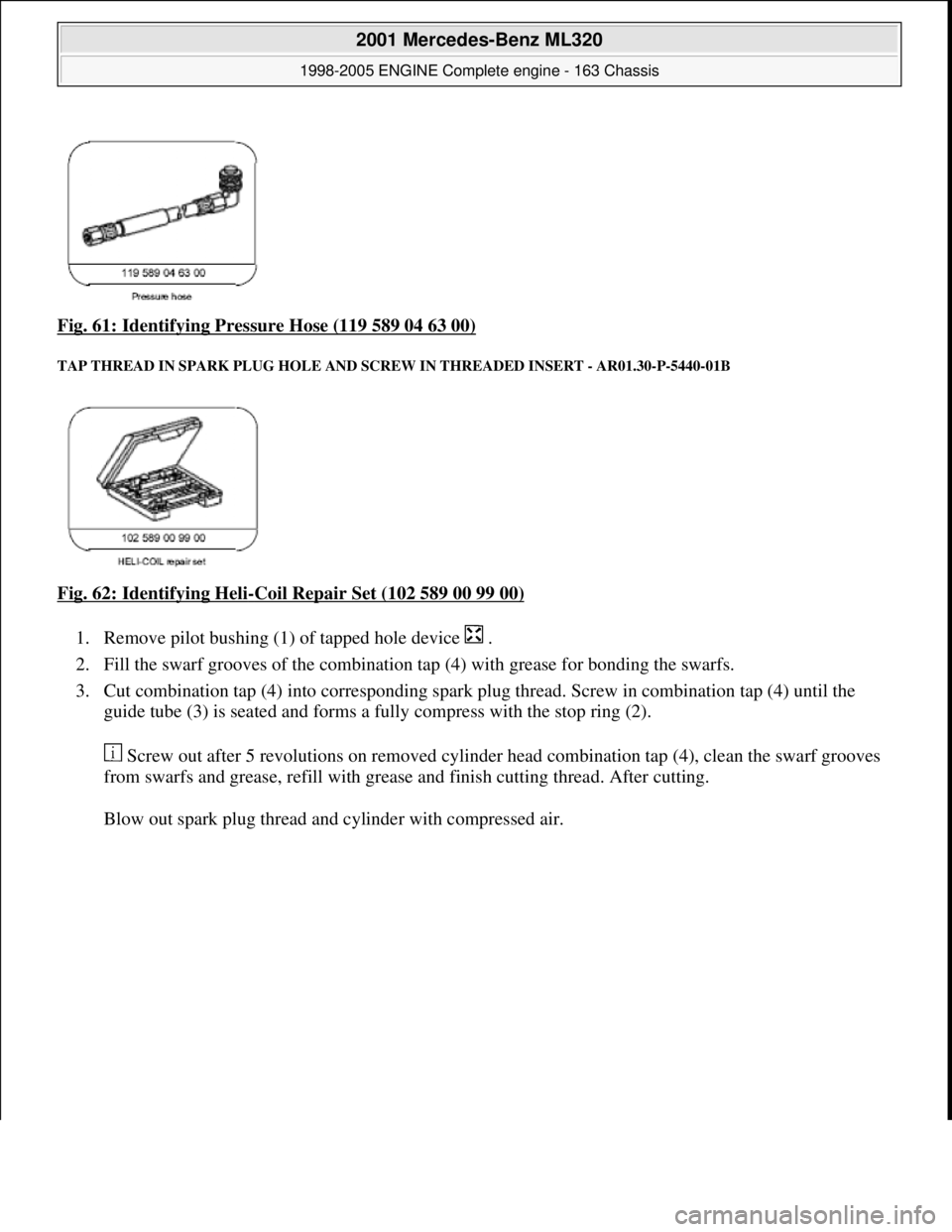
Fig. 61: Identifying Pressure Hose (119 589 04 63 00)
TAP THREAD IN SPARK PLUG HOLE AND SCRE W IN THREADED INSERT - AR01.30-P-5440-01B
Fig. 62: Identifying Heli-Coil Repair Set (102 589 00 99 00)
1. Remove pilot bushing (1) of tapped hole device .
2. Fill the swarf grooves of the combination tap (4) with grease for bonding the swarfs.
3. Cut combination tap (4) into corresponding spark pl ug thread. Screw in combination tap (4) until the
guide tube (3) is seated and forms a fully compress with the stop ring (2).
Screw out after 5 revolutions on removed cylinder head combination tap (4), clean the swarf grooves
from swarfs and grease, refi ll with grease and finish cutting thread. After cutting.
Blow out spark plu
g thread and cylinder with compressed air.
2001 Mercedes-Benz ML320
1998-2005 ENGINE Complete engine - 163 Chassis
me
Saturday, October 02, 2010 3:17:56 PMPage 70 © 2006 Mitchell Repair Information Company, LLC.
Page 2430 of 4133
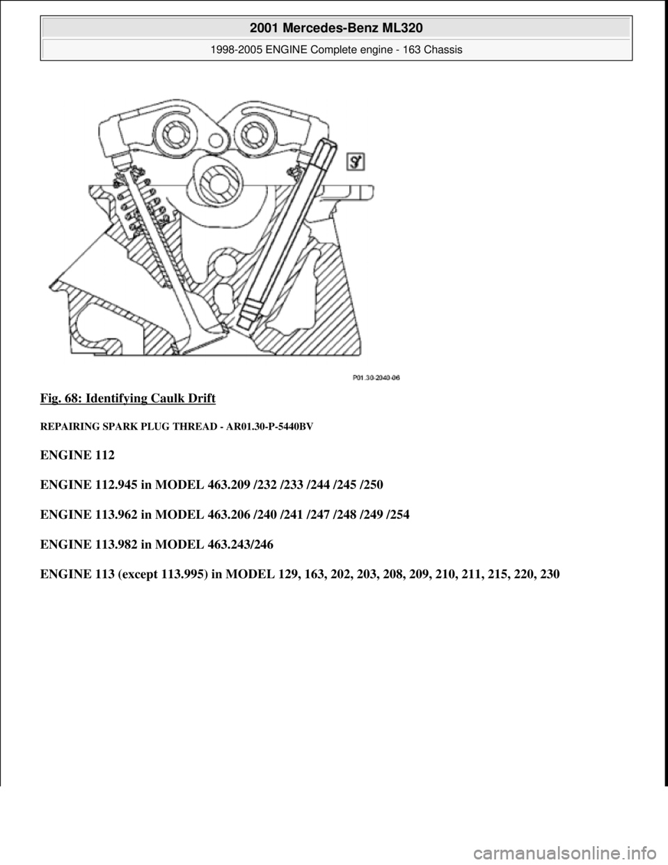
Fig. 68: Identifying Caulk Drift
REPAIRING SPARK PLUG THREAD - AR01.30-P-5440BV
ENGINE 112
ENGINE 112.945 in MODEL 463.209 /232 /233 /244 /245 /250
ENGINE 113.962 in MODEL 463.206 /240 /241 /247 /248 /249 /254
ENGINE 113.982 in MODEL 463.243/246
ENGINE 113 (except 113.995) in MODEL 129, 163, 202, 203, 208, 209, 210, 211, 215, 220, 230
2001 Mercedes-Benz ML320
1998-2005 ENGINE Complete engine - 163 Chassis
me
Saturday, October 02, 2010 3:17:56 PMPage 74 © 2006 Mitchell Repair Information Company, LLC.
Page 2431 of 4133
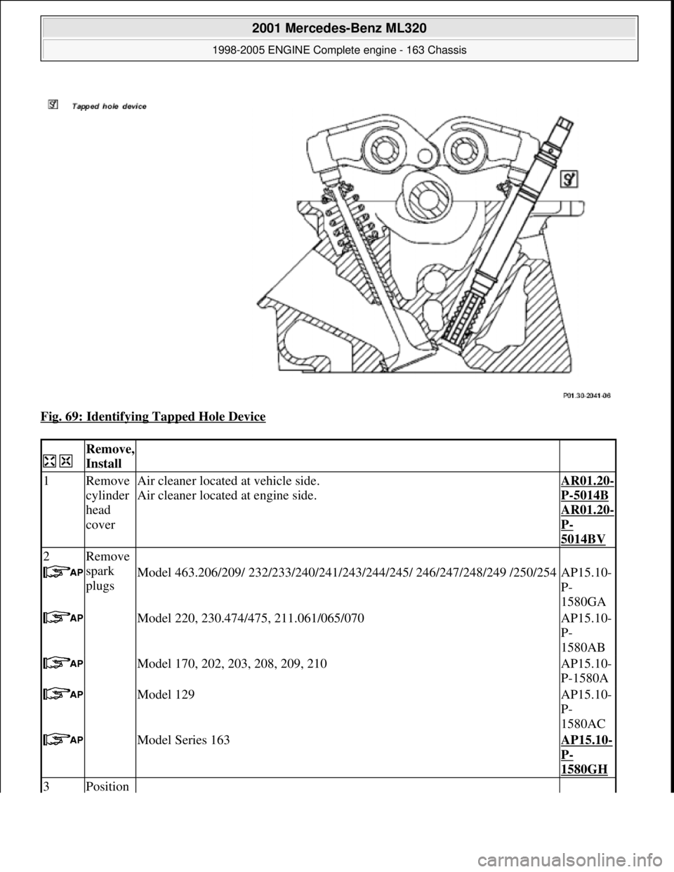
Fig. 69: Identifying Tapped Hole Device
Remove,
Install
1Remove
cylinder
head
coverAir cleaner located at vehicle side.
Air cleaner located at engine side.AR01.20-
P-5014B
AR01.20-
P-
5014BV
2Remove
spark
plugs
Model 463.206/209/ 232/233/240/241/243/ 244/245/ 246/247/248/249 /250/254AP15.10-
P-
1580GA
Model 220, 230.474/475, 211.061/065/070AP15.10-
P-
1580AB
Model 170, 202, 203, 208, 209, 210AP15.10-
P-1580A
Model 129AP15.10-
P-
1580AC
Model Series 163AP15.10-
P-
1580GH
3Position
2001 Mercedes-Benz ML320
1998-2005 ENGINE Complete engine - 163 Chassis
me
Saturday, October 02, 2010 3:17:56 PMPage 75 © 2006 Mitchell Repair Information Company, LLC.
Page 2432 of 4133
piston of
relevant
cylinder
to 20° -
30°
before
TDC Inlet valve and exhaust valve of th e relevant cylinder must be closed.
4Remove
cylinder
head Model 230.474 with Engine 113.992 repla ce cylinder head if spark plug
thread is faulty.
It is then only necessary to remove the cylinder head if it is not possible to
insert the thread tap unit into the spark plug thread for space reasons!
Model
463.206 /209 /232 /233 /240 /241 /243 /244 /245 /246 /247 /248 /249 /250 /254.AR01.30-
P-
5800GV
Model 202, 208, 210 with Engine 113 and Model 129 with Engine 112, 113AR01.30-
P-5800B
Model 220 with Engine 112, 113 and Model 210, 170, 202, 208 with Engine
112, 230.474/475AR01.30-
P-
5800BA
Model 203, 209, 211.061/065 /070AR01.30-
P-
5800PV
Model Series 163AR01.30-
P-
5800MV
5Tap
thread in
spark
plug
hole and
screw in
threaded
insert Pack the swarf grooves of the combin ation thread tap with grease for
bonding the swarf. Blow out cylinder and spark plug thread with compressed
air before screwing in the threaded insert.AR01.30-
P-5440-
01B
Fig. 62
6Crank
engine
with
starter. If the cylinder head was not removed, the engine must be cranked several
times with the starter.
All Models except Mode l 203, 209 Model 203, 209AR01.10-
P-0110V
AR01.10-
P-
0110PV
7Caulk
threaded
insert AR01.30-
P-5440-
02B
8Install in
the
reverse
order
2001 Mercedes-Benz ML320
1998-2005 ENGINE Complete engine - 163 Chassis
me
Saturday, October 02, 2010 3:17:56 PMPage 76 © 2006 Mitchell Repair Information Company, LLC.
Page 2440 of 4133
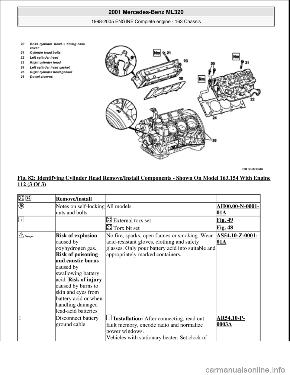
Fig. 82: Identifying Cylinder Head Remove/Install Components - Shown On Model 163.154 With Engine
112 (3 Of 3)
Remove/install
Notes on self-locking
nuts and boltsAll modelsAH00.00-N-0001-
01A
External torx setFig. 49
Torx bit setFig. 48
Risk of explosion
caused by
oxyhydrogen gas.
Risk of poisoning
and caustic burns
caused by
swallowing battery
acid. Risk of injury
caused by burns to
skin and eyes from
battery acid or when
handling damaged
lead-acid batteriesNo fire, sparks, open fl ames or smoking. Wear
acid-resistant gloves, clothing and safety
glasses. Only pour batter y acid into suitable and
appropriately marked containers.AS54.10-Z-0001-
01A
1Disconnect battery
ground cable Installation: After connecting, read out
fault memory, encode radio and normalize
power windows.
Vehicles with stationary heater: Set clock of AR54.10-P-
0003A
2001 Mercedes-Benz ML320
1998-2005 ENGINE Complete engine - 163 Chassis
me
Saturday, October 02, 2010 3:17:57 PMPage 84 © 2006 Mitchell Repair Information Company, LLC.
Page 2442 of 4133
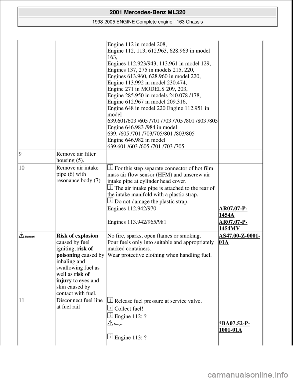
Engine 112 in model 208,
Engine 112, 113, 612.963, 628.963 in model
163,
Engines 112.923/943, 113.961 in model 129,
Engines 137, 275 in models 215, 220,
Engines 613.960, 628.960 in model 220,
Engine 113.992 in model 230.474,
Engine 271 in MODELS 209, 203,
Engine 285.950 in models 240.078 /178,
Engine 612.967 in model 209.316,
Engine 648 in model 220 Engine 112.951 in
model
639.601/603 /605 /701 /703 /705 /801 /803 /805
Engine 646.983 /984 in model
639. /605 /701 /703/705/801 /803/805
Engine 646.982 in model
639.601 /603 /605 /701 /703 /705
9Remove air filter
housing (5).
10Remove air intake
pipe (6) with
resonance body (7) For this step separate connector of hot film
mass air flow sensor (HFM) and unscrew air
intake pipe at cylinder head cover.
The air intake pipe is attached to the rear of
the intake manifold with a plastic strap.
Do not damage the plastic strap.
Engines 112.942/970AR07.07-P-
1454A
Engines 113.942/965/981AR07.07-P-
1454MV
Risk of explosion
caused by fuel
igniting, risk of
poisoning caused by
inhaling and
swallowing fuel as
well as risk of
injury to eyes and
skin caused by
contact with fuel.No fire, sparks, open flames or smoking.
Pour fuels only into suitable and appropriately
marked containers.
Wear protective clothing when handling fuel.AS47.00-Z-0001-
01A
11Disconnect fuel line
at fuel rail Release fuel pressure at service valve.
Collect fuel!
Engine 112: ?
*BA07.52-P-
1001-01A
Engine 113: ?
2001 Mercedes-Benz ML320
1998-2005 ENGINE Complete engine - 163 Chassis
me
Saturday, October 02, 2010 3:17:57 PMPage 86 © 2006 Mitchell Repair Information Company, LLC.
Page 2453 of 4133
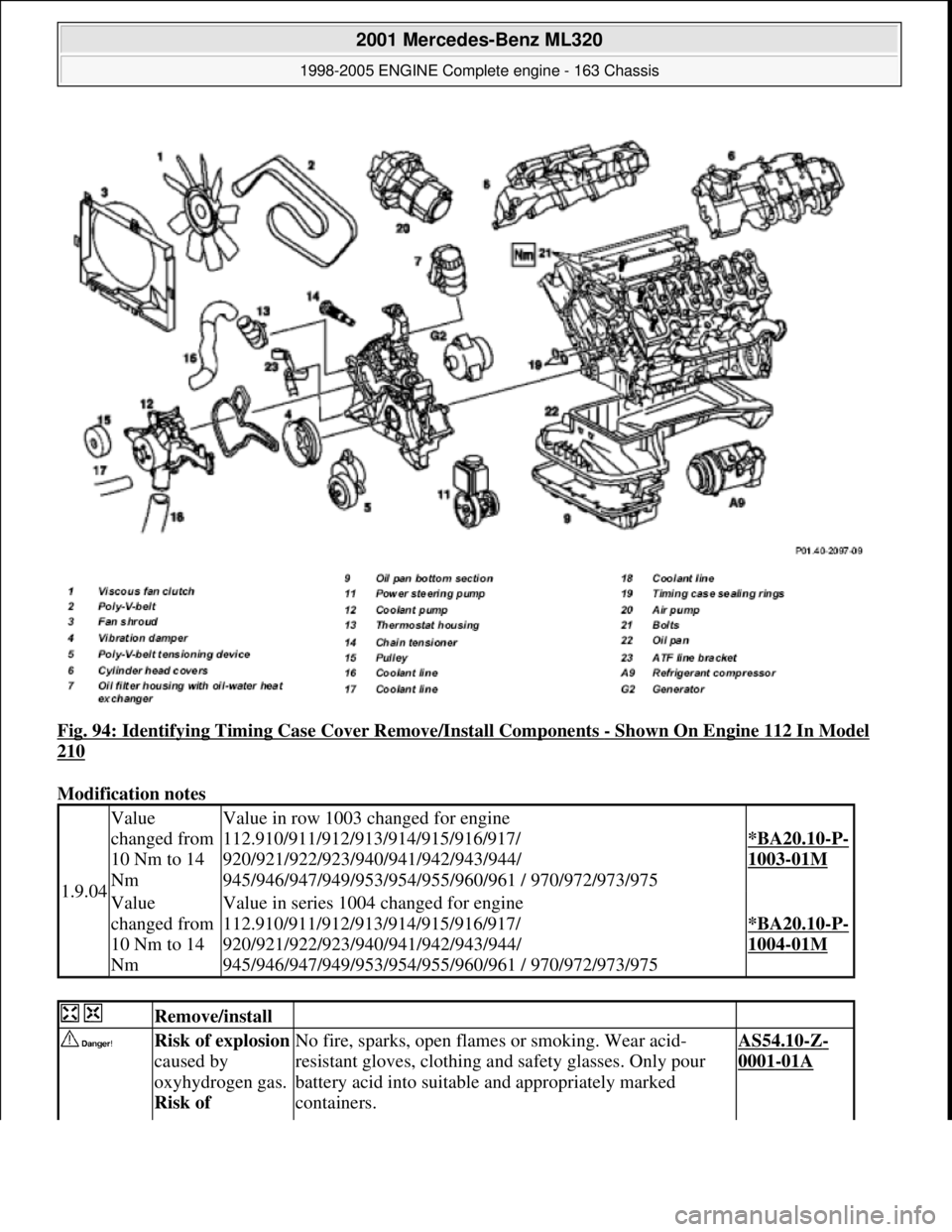
Fig. 94: Identifying Timing Case Cover Remove/Install Components - Shown On Engine 112 In Model
210
Modification notes
1.9.04
Value
changed from
10 Nm to 14
NmValue in row 1003 changed for engine
112.910/911/912/913/914/915/916/917/
920/921/922/923/940/941/942/943/944/
945/946/947/949/953/954/955/960/961 / 970/972/973/975
*BA20.10-P-
1003-01M
Value
changed from
10 Nm to 14
NmValue in series 1004 changed for engine
112.910/911/912/913/914/915/916/917/
920/921/922/923/940/941/942/943/944/
945/946/947/949/953/954/955/960/961 / 970/972/973/975
*BA20.10-P-
1004-01M
Remove/install
Risk of explosion
caused by
oxyhydrogen gas.
Risk of No fire, sparks, open fl ames or smoking. Wear acid-
resistant gloves, clothing and safety glasses. Only pour
battery acid into suitable and appropriately marked
containers.AS54.10-Z-
0001-01A
2001 Mercedes-Benz ML320
1998-2005 ENGINE Complete engine - 163 Chassis
me
Saturday, October 02, 2010 3:17:57 PMPage 97 © 2006 Mitchell Repair Information Company, LLC.