MERCEDES-BENZ ML350 1997 Complete Repair Manual
Manufacturer: MERCEDES-BENZ, Model Year: 1997, Model line: ML350, Model: MERCEDES-BENZ ML350 1997Pages: 4133, PDF Size: 88.89 MB
Page 3841 of 4133
1998-2005 ACCESSORIES & BODY CAB
Throttle Control, Speed Control Systems - 163 Chassis
BASIC KNOWLEDGE
ELECTRONIC ACCELERATOR, LOCATION/DESIGN/FUNCTION - GF30.20-P-3010E
ENGINE 104.941 /943 /944 /991 /994 as of 1/8/96
ENGINE 104.995
with CODE (494a) USA version
with CODE (807) Model year 1997
with CODE (808) Model year 1998
with CODE (498) as of Model year 97 Japanese version
ENGINE 111.943 /947 /951 /952 /955 /956 /957 /958 /973 /982 /983,
111.944/975 as of 1.8.96,
111.946 as of 1.6.98,
111.921/942 as of 1.9.98
ENGINE 111.945
in MODEL 208.335 /435 as of 1.6.98,
202.020/080 as of 1.9.98
ENGINE 111.974
with CODE (494a) USA version
with CODE (807) Model year 1997
with CODE (808) Model year 1998
ENGINE
112.910 /911 /912 /913 /914 /916 /917 /920 /921 /922 /923 /940 /941 /942 /943 /944 /946 /947 /949 /953 /954 /9
5
ENGINE 113.940 /941 /942 /943 /948 /960 /961 /963 /965 /966 /967 /968 /969
2001 Mercedes-Benz ML320
1998-2005 ACCESSORIES & BODY CAB Throttle Control, Speed Control Systems - 163 Chassis
2001 Mercedes-Benz ML320
1998-2005 ACCESSORIES & BODY CAB Throttle Control, Speed Control Systems - 163 Chassis
me
Saturday, October 02, 2010 3:36:27 PMPage 1 © 2006 Mitchell Repair Information Company, LLC.
me
Saturday, October 02, 2010 3:36:30 PMPage 1 © 2006 Mitchell Repair Information Company, LLC.
Page 3842 of 4133
ENGINE 119.980 /981 /982 /985
ENGINE 137.970
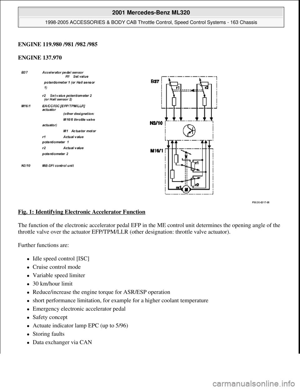
Fig. 1: Identifying Electronic Accelerator Function
The function of the electronic accelerator pedal EFP in the ME control unit determines the opening angle of the
throttle valve over the actuator EFP/TPM/LLR (other designation: throttle valve actuator).
Further functions are:
Idle speed control [ISC]
Cruise control mode
Variable speed limiter
30 km/hour limit
Reduce/increase the engine torque for ASR/ESP operation
short performance limitation, for example for a higher coolant temperature
Emergency electronic accelerator pedal
Safety concept
Actuate indicator lamp EPC (up to 5/96)
Storing faults
Data exchanger via CAN
2001 Mercedes-Benz ML320
1998-2005 ACCESSORIES & BODY CAB Throttle Control, Speed Control Systems - 163 Chassis
me
Saturday, October 02, 2010 3:36:27 PMPage 2 © 2006 Mitchell Repair Information Company, LLC.
Page 3843 of 4133
The opening angle of the throttle valve will only be determined by the accelerator pedal specification when no
limiting functions are active.
The accelerator pedal position is detected by the set value potentiometer (B37r1) or Hall sensor in the pedal
value sensor (B37) and information is released to the ME control unit (N3/10). In this way, the ME-SFI control
unit determines the position of the throttle valve and actuates the throttle valve motor (M16/1 m1).
The actual value potentiometer in the actuator (M16/1r1) signals the throttle valve position back to the ME-SFI
control unit.
The second potentiometer in the actuator (M16/1 r2) and the second signal from the pedal value sensor
(potentiometer or Hall sensor) supplies a reference value for the plausibility check. In addition, the system
switches over to the second potentiometer or the Hall sensor if the first potentiometer or Hall sensor fails
(emergency mode).
Adaptive accelerator pedal (model 203, 209, 211, 215, 220, 230):
The engine control unit recognizes how the accelerator pedal is being actuated and switches between
characteristic curves. Eighty percent of the engine load is released for a pedal travel of about 50 % for a sporty
driver and about 40 % for a quiet driver. There is no further difference felt above a pedal travel of about 90 %.
If, for example, the characteristic curve for a quiet driver is active after a long drive on the motorway then the
accelerator pedal must be pressed down unusually hard to obtain a higher acceleration level.
Kickdown switch (S16/6)
The kickdown switch was no longer used from 9/01. Recognition of full load is now achieved over the signal
from the pedal value sensor. The pressure point on the accelerator pedal before achieving the full load position
remains.
Motor electronics control unit, location/task/
design/functionexcept M111 EVOGF07.61-P-
5000F
M111 EVOGF07.61-P-
5000GS
Electronic accelerator/cruise control/idle speed
control actuator location/task/design/functionexcept M111 EVOGF30.22-P-
4010F
Throttle valve actuator, location/task/design/
functionM111 EVOGF30.22-P-
4101GS
Pedal value sensor, location/task/design/
function GF30.20-P-
4011L
ME-SFI idle speed control function
Except engine 120 and engine 111 EVOGF30.22-P-
0003E
M111 EVOGF30.22-P-
0003GS
2001 Mercedes-Benz ML320
1998-2005 ACCESSORIES & BODY CAB Throttle Control, Speed Control Systems - 163 Chassis
me
Saturday, October 02, 2010 3:36:27 PMPage 3 © 2006 Mitchell Repair Information Company, LLC.
Page 3844 of 4133
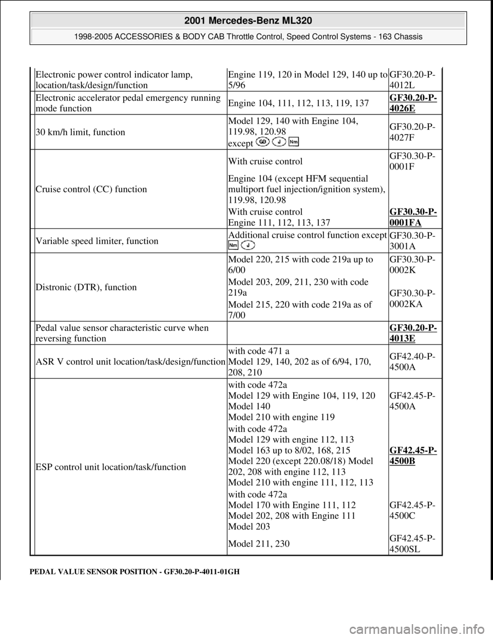
PEDAL VALUE SENSOR PO SITION - GF30.20-P-4011-01GH
Electronic power control indicator lamp,
location/task/design/functionEngine 119, 120 in Model 129, 140 up to
5/96GF30.20-P-
4012L
Electronic accelerator pe dal emergency running
mode functionEngine 104, 111, 112, 113, 119, 137GF30.20-P-
4026E
30 km/h limit, function
Model 129, 140 with Engine 104,
119.98, 120.98
except GF30.20-P-
4027F
Cruise control (CC) function
With cruise controlGF30.30-P-
0001F
Engine 104 (except HFM sequential
multiport fuel injection/ignition system),
119.98, 120.98
With cruise control
Engine 111, 112, 113, 137GF30.30-P-
0001FA
Variable speed limiter, functionAdditional cruise control function except
GF30.30-P-
3001A
Distronic (DTR), function
Model 220, 215 with code 219a up to
6/00GF30.30-P-
0002K
Model 203, 209, 211, 230 with code
219a
GF30.30-P-
0002KA
Model 215, 220 with code 219a as of
7/00
Pedal value sensor characteristic curve when
reversing function GF30.20-P-
4013E
ASR V control unit location/task/design/function
with code 471 a
Model 129, 140, 202 as of 6/94, 170,
208, 210GF42.40-P-
4500A
ESP control unit location/task/function
with code 472a
Model 129 with Engine 104, 119, 120
Model 140
Model 210 with engine 119
GF42.45-P-
4500A
with code 472a
Model 129 with engine 112, 113
Model 163 up to 8/02, 168, 215
Model 220 (except 220.08/18) Model
202, 208 with engine 112, 113
Model 210 with engine 111, 112, 113
GF42.45-P-
4500B
with code 472a
Model 170 with Engine 111, 112
Model 202, 208 with Engine 111
Model 203
GF42.45-P-
4500C
Model 211, 230GF42.45-P-
4500SL
2001 Mercedes-Benz ML320
1998-2005 ACCESSORIES & BODY CAB Throttle Control, Speed Control Systems - 163 Chassis
me
Saturday, October 02, 2010 3:36:27 PMPage 4 © 2006 Mitchell Repair Information Company, LLC.
Page 3845 of 4133
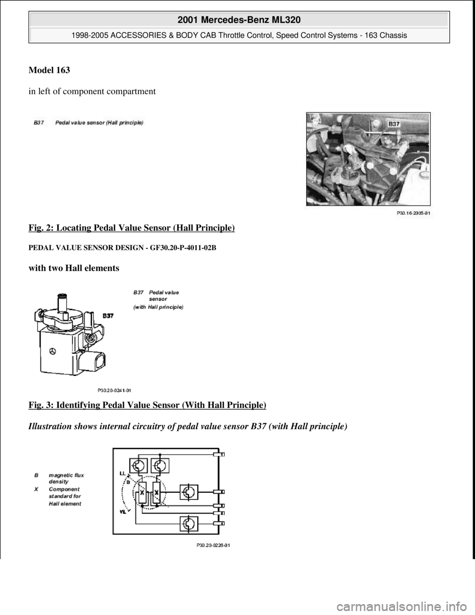
Model 163
in left of component compartment
Fig. 2: Locating Pedal Valu e Sensor (Hall Principle)
PEDAL VALUE SENSOR DE SIGN - GF30.20-P-4011-02B
with two Hall elements
Fig. 3: Identifying Pedal Value Sensor (With Hall Principle)
Illustration shows internal circuitry of pedal value sensor B37 (with Hall principle)
2001 Mercedes-Benz ML320
1998-2005 ACCESSORIES & BODY CAB Throttle Control, Speed Control Systems - 163 Chassis
me
Saturday, October 02, 2010 3:36:27 PMPage 5 © 2006 Mitchell Repair Information Company, LLC.
Page 3846 of 4133
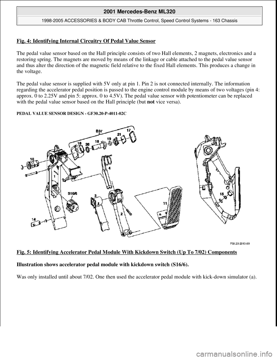
Fig. 4: Identifying Internal Circuitry Of Pedal Value Sensor
The pedal value sensor based on the Hall principle consists of two Hall elements, 2 magnets, electronics and a
restoring spring. The magnets are moved by means of the linkage or cable attached to the pedal value sensor
and thus alter the direction of the magnetic field relative to the fixed Hall elements. This produces a change in
the voltage.
The pedal value sensor is supplied with 5V only at pin 1. Pin 2 is not connected internally. The information
regarding the accelerator pedal position is passed to the engine control module by means of two voltages (pin 4:
approx. 0 to 2.25V and pin 5: approx. 0 to 4.5V). The pedal value sensor with potentiometer can be replaced
with the pedal value sensor based on the Hall principle (but not vice versa).
PEDAL VALUE SENSOR DESIGN - GF30.20-P-4011-02C
Fig. 5: Identifying Accelerator Pedal Module With Kickdown Switch (Up To 7/02) Components
Illustration shows accelerator pedal module with kickdown switch (S16/6).
Was onl
y installed until about 7/02. One then used the accelerator pedal module with kick-down simulator (a).
2001 Mercedes-Benz ML320
1998-2005 ACCESSORIES & BODY CAB Throttle Control, Speed Control Systems - 163 Chassis
me
Saturday, October 02, 2010 3:36:27 PMPage 6 © 2006 Mitchell Repair Information Company, LLC.
Page 3847 of 4133
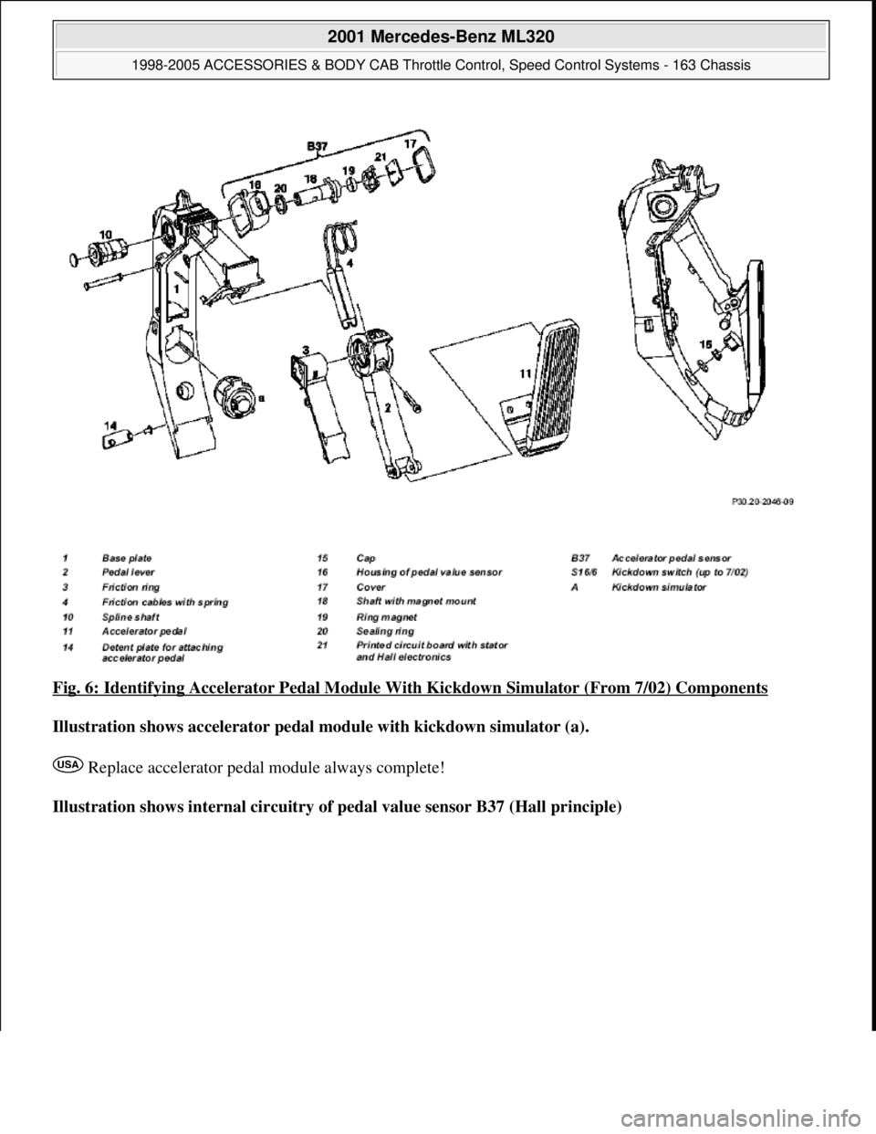
Fig. 6: Identifying Accelerator Pedal Module With Kickdown Simulator (From 7/02) Components
Illustration shows accelerator pedal module with kickdown simulator (a).
Replace accelerator pedal module always complete!
Illustration shows internal circuitry of pedal value sensor B37 (Hall principle)
2001 Mercedes-Benz ML320
1998-2005 ACCESSORIES & BODY CAB Throttle Control, Speed Control Systems - 163 Chassis
me
Saturday, October 02, 2010 3:36:27 PMPage 7 © 2006 Mitchell Repair Information Company, LLC.
Page 3848 of 4133
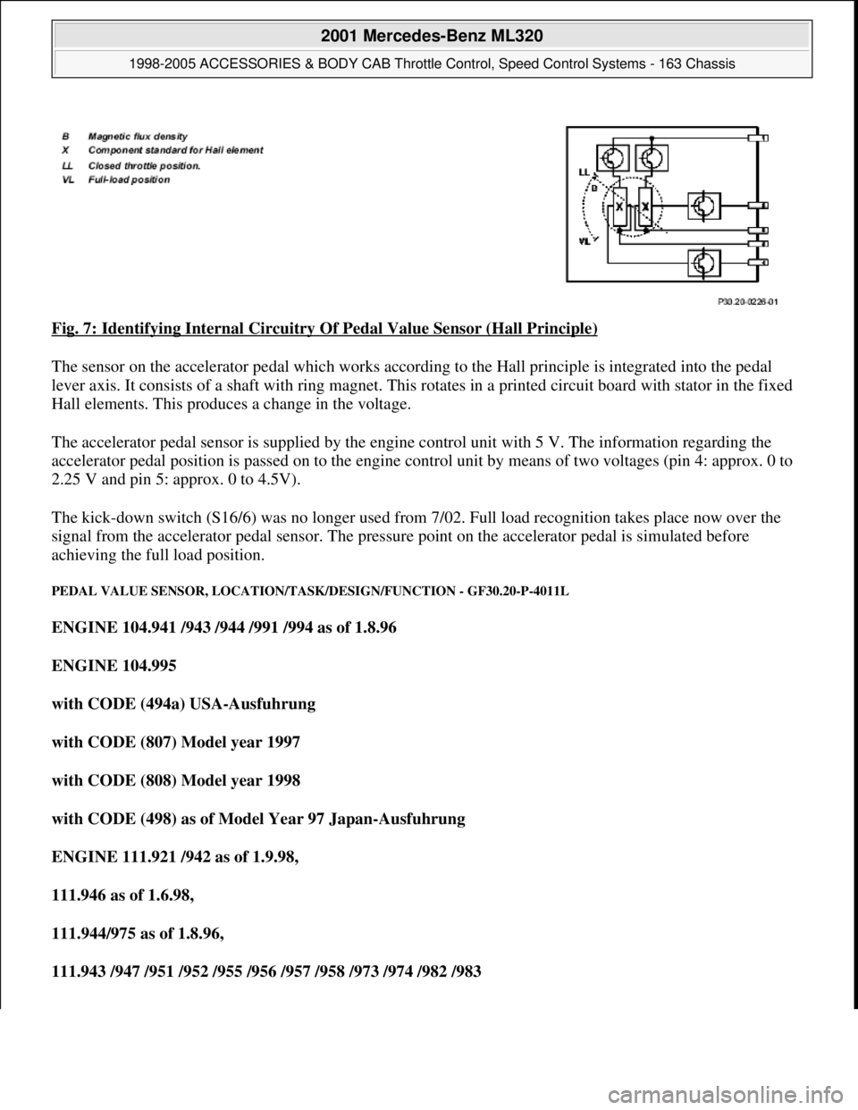
Fig. 7: Identifying Internal Circuitry Of Pedal Value Sensor (Hall Principle)
The sensor on the accelerator pedal which works according to the Hall principle is integrated into the pedal
lever axis. It consists of a shaft with ring magnet. This rotates in a printed circuit board with stator in the fixed
Hall elements. This produces a change in the voltage.
The accelerator pedal sensor is supplied by the engine control unit with 5 V. The information regarding the
accelerator pedal position is passed on to the engine control unit by means of two voltages (pin 4: approx. 0 to
2.25 V and pin 5: approx. 0 to 4.5V).
The kick-down switch (S16/6) was no longer used from 7/02. Full load recognition takes place now over the
signal from the accelerator pedal sensor. The pressure point on the accelerator pedal is simulated before
achieving the full load position.
PEDAL VALUE SENSOR, LOCATION/TASK/DESIGN/FUNCTION - GF30.20-P-4011L
ENGINE 104.941 /943 /944 /991 /994 as of 1.8.96
ENGINE 104.995
with CODE (494a) USA-Ausfuhrung
with CODE (807) Model year 1997
with CODE (808) Model year 1998
with CODE (498) as of Model Year 97 Japan-Ausfuhrung
ENGINE 111.921 /942 as of 1.9.98,
111.946 as of 1.6.98,
111.944/975 as of 1.8.96,
111.943 /947 /951 /952 /955 /956 /957 /958 /973 /974 /982 /983
2001 Mercedes-Benz ML320
1998-2005 ACCESSORIES & BODY CAB Throttle Control, Speed Control Systems - 163 Chassis
me
Saturday, October 02, 2010 3:36:27 PMPage 8 © 2006 Mitchell Repair Information Company, LLC.
Page 3849 of 4133
ENGINE 111.945
in MODEL 202.020 /080 as of 1.9.98,
208.335/435 as of 1.6.98
with CODE (494a) USA-Ausfuhrung
with CODE (807) Model year 1997
with CODE (808) Model year 1998
ENGINE
112.910 /911 /912 /913 /914 /916 /917 /920 /921 /922 /923 /940 /941 /942 /943 /944 /946 /947 /949 /953 /954 /9
5
ENGINE 113.940 /941 /942 /943 /948 /960 /961 /963 /965 /966 /967 /968 /969
ENGINE 119.980 /981 /982 /985
ENGINE 120.982 /983
ENGINE 137.970
ENGINE 166.940 /960 /990 /995
ENGINE 604.910/915 as of 1.2.98
ENGINE 604.912/917 as of 1.4.98
ENGINE 611.961/960/962
ENGINE 612.961/962/963
ENGINE 613.960/961
ENGINE 628.960 /963
ENGINE 668.940 /941 /942
ENGINE 612.967 in MODEL 209.316
Shown on model 203, 215, 220
2001 Mercedes-Benz ML320
1998-2005 ACCESSORIES & BODY CAB Throttle Control, Speed Control Systems - 163 Chassis
me
Saturday, October 02, 2010 3:36:27 PMPage 9 © 2006 Mitchell Repair Information Company, LLC.
Page 3850 of 4133
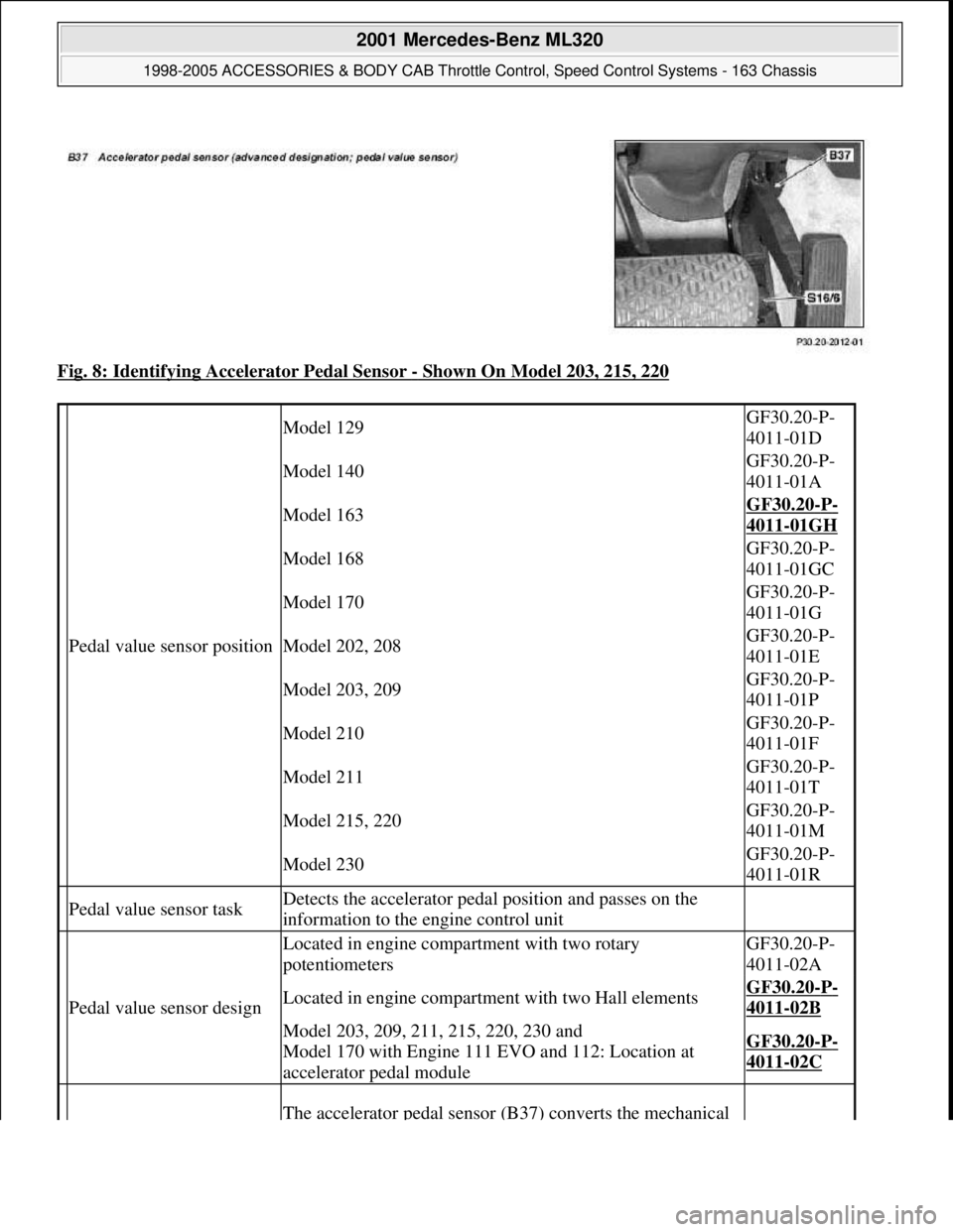
Fig. 8: Identifying Accelerator Pedal Sensor - Shown On Model 203, 215, 220
Pedal value sensor position
Model 129GF30.20-P-
4011-01D
Model 140GF30.20-P-
4011-01A
Model 163GF30.20-P-
4011-01GH
Model 168GF30.20-P-
4011-01GC
Model 170GF30.20-P-
4011-01G
Model 202, 208GF30.20-P-
4011-01E
Model 203, 209GF30.20-P-
4011-01P
Model 210GF30.20-P-
4011-01F
Model 211GF30.20-P-
4011-01T
Model 215, 220GF30.20-P-
4011-01M
Model 230GF30.20-P-
4011-01R
Pedal value sensor taskDetects the accelerator pedal position and passes on the
information to the engine control unit
Pedal value sensor design
Located in engine compartment with two rotary
potentiometersGF30.20-P-
4011-02A
Located in engine compartment with two Hall elementsGF30.20-P-
4011-02B
Model 203, 209, 211, 215, 220, 230 and
Model 170 with Engine 111 EVO and 112: Location at
accelerator pedal moduleGF30.20-P-
4011-02C
The accelerator pedal sensor (B37) converts the mechanical
2001 Mercedes-Benz ML320
1998-2005 ACCESSORIES & BODY CAB Throttle Control, Speed Control Systems - 163 Chassis
me
Saturday, October 02, 2010 3:36:27 PMPage 10 © 2006 Mitchell Repair Information Company, LLC.