MERCEDES-BENZ ML350 1997 Complete Repair Manual
Manufacturer: MERCEDES-BENZ, Model Year: 1997, Model line: ML350, Model: MERCEDES-BENZ ML350 1997Pages: 4133, PDF Size: 88.89 MB
Page 3871 of 4133

Risk of injury!
Class 2 lasers emit a visible radiation. Looking directly into the laser beam can result in damage to the eye.
The reflected laser beam can likewise cause damage to the eye.
For this reason, avoid reflections of the laser beam by using mirrors and similar aids. Laser beams may also
cause skin damage.
Safety instructions/precautions
Never look directly into the laser beam.
Do not attempt to suppress the natural reflex of the eyelids.
The eye is normally protected by defensive reactions including the reflex of the eyelid closing.
Avoid direct skin contact with the laser beam.
If damage to the eye is suspected, consult an eye specialist immediately.
It is prohibited to further bundle the laser beam and thus to concentrate the energy (increasing the laser
class).
Only properly instructed personnel may be entrusted with the work on this equipment.
TESTING & REPAIR
ADJUST THROTTLE CONTROL - AR30.10-P-1010GJ
ENGINE 112.942 #2 in MODEL 163.154
ENGINE 112.970 #2 in MODEL 163.157
ENGINE 113.942 #2 in MODEL 163.172
ENGINE 113.981 #2 in MODEL 163.174
ENGINE 113.965 #2 in MODEL 163.175
Shown on Engine 112.942 in Model 163.154
2001 Mercedes-Benz ML320
1998-2005 ACCESSORIES & BODY CAB Throttle Control, Speed Control Systems - 163 Chassis
me
Saturday, October 02, 2010 3:36:27 PMPage 31 © 2006 Mitchell Repair Information Company, LLC.
Page 3872 of 4133
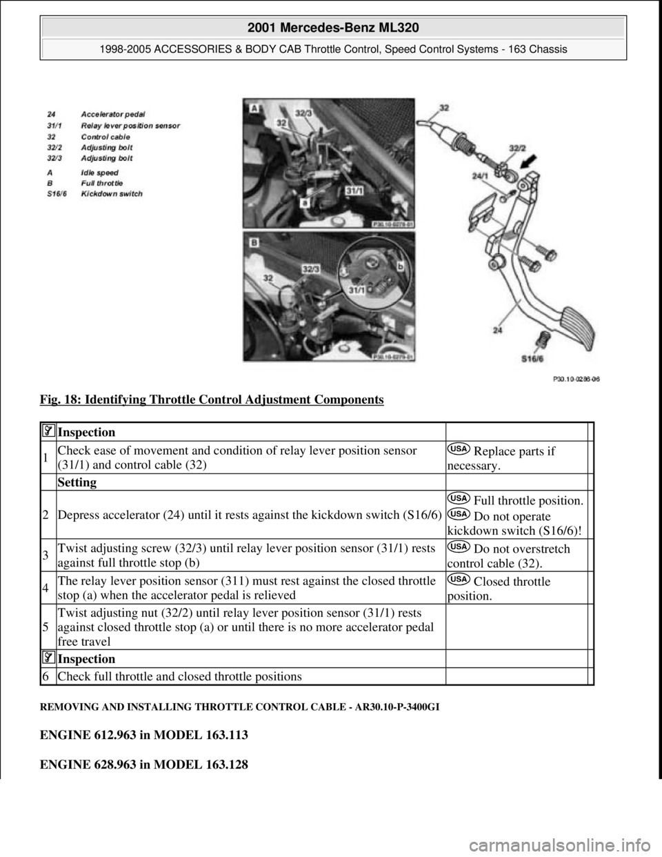
Fig. 18: Identifying Throttle Control Adjustment Components
REMOVING AND INSTALLING THROTTLE CONTROL CABLE - AR30.10-P-3400GI
ENGINE 612.963 in MODEL 163.113
ENGINE 628.963 in MODEL 163.128
Inspection
1Check ease of movement and condition of relay lever position sensor
(31/1) and control cable (32) Replace parts if
necessary.
Setting
2Depress accelerator (24) until it rests against the kickdown switch (S16/6)
Full throttle position.
Do not operate
kickdown switch (S16/6)!
3Twist adjusting screw (32/3) until relay lever position sensor (31/1) rests
against full throttle stop (b) Do not overstretch
control cable (32).
4The relay lever position sensor (311) must rest against the closed throttle
stop (a) when the accelerator pedal is relieved Closed throttle
position.
5
Twist adjusting nut (32/2) until relay lever position sensor (31/1) rests
against closed throttle stop (a) or until there is no more accelerator pedal
free travel
Inspection
6Check full throttle and closed throttle positions
2001 Mercedes-Benz ML320
1998-2005 ACCESSORIES & BODY CAB Throttle Control, Speed Control Systems - 163 Chassis
me
Saturday, October 02, 2010 3:36:28 PMPage 32 © 2006 Mitchell Repair Information Company, LLC.
Page 3873 of 4133
ENGINE 112.942 in MODEL 163.154
ENGINE 112.970 in MODEL 163.157
ENGINE 113.942 in MODEL 163.172
ENGINE 113.981 in MODEL 163.174
ENGINE 113.965 in MODEL 163.175
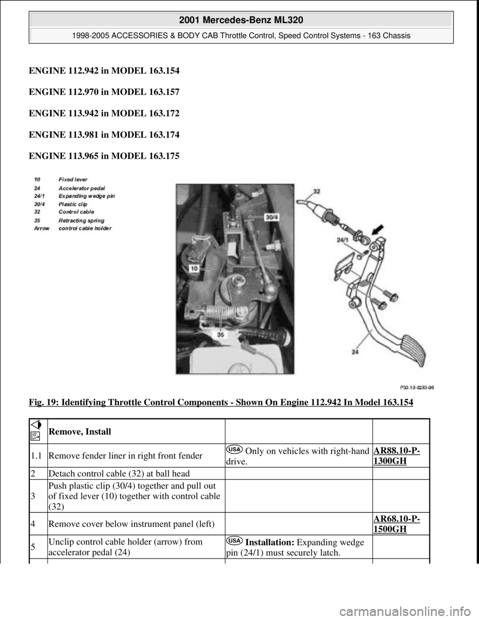
Fig. 19: Identifying Throttle Control Components
- Shown On Engine 112.942 In Model 163.154
Remove, Install
1.1Remove fender liner in right front fender Only on vehicles with right-hand
drive.AR88.10-P-
1300GH
2Detach control cable (32) at ball head
3
Push plastic clip (30/4) together and pull out
of fixed lever (10) together with control cable
(32)
4Remove cover below instrument panel (left) AR68.10-P-
1500GH
5Unclip control cable holder (arrow) from
accelerator pedal (24) Installation: Expanding wedge
pin (24/1) must securely latch.
2001 Mercedes-Benz ML320
1998-2005 ACCESSORIES & BODY CAB Throttle Control, Speed Control Systems - 163 Chassis
me
Saturday, October 02, 2010 3:36:28 PMPage 33 © 2006 Mitchell Repair Information Company, LLC.
Page 3874 of 4133
REMOVING AND INSTALLING ACCELERATOR PEDAL - AR30.12-P-1321GH
ENGINE 111.977 in MODEL 163.136
ENGINE 112.942 in MODEL 163.154
ENGINE 112.970 in MODEL 163.157
ENGINE 113.981 in MODEL 163.174
6Push control cable (32) from vehicle interior
towards the outside Do not push rubber grommet out
of splash wall.
7Remove entire control cable (32) from engine
compartment
8Install in the reverse order
9Check throttle control, adjust
Engine 112.942/970,
113.942/965/981 ?
Automatic transmissionAR30.10-P-
1010GJ
Engine 612.963: ?
Manual/automatic transmissionAR30.10-P-
1010GH
Engine 628.963: ?
Automatic transmissionAR30.10-P-
1010GH
2001 Mercedes-Benz ML320
1998-2005 ACCESSORIES & BODY CAB Throttle Control, Speed Control Systems - 163 Chassis
me
Saturday, October 02, 2010 3:36:28 PMPage 34 © 2006 Mitchell Repair Information Company, LLC.
Page 3875 of 4133
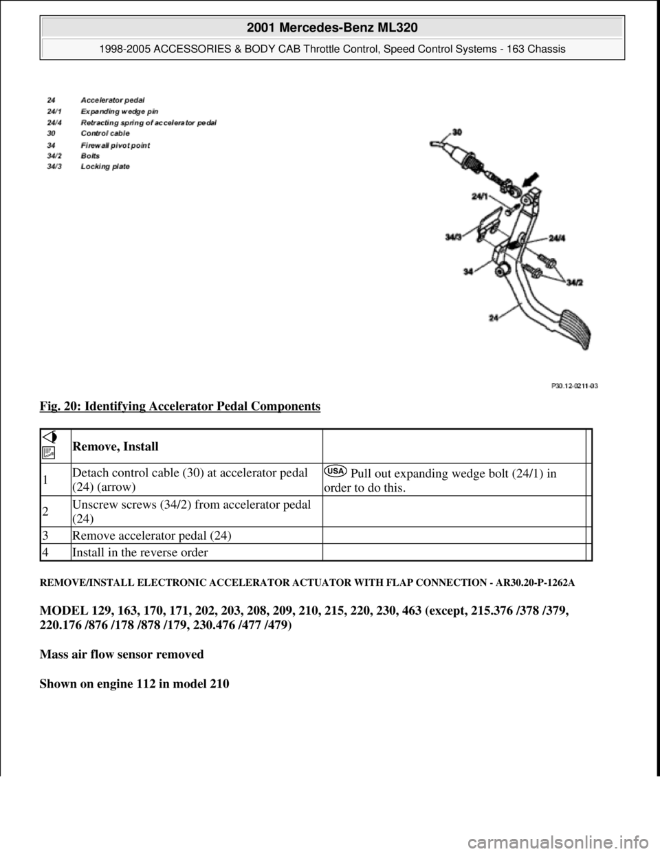
Fig. 20: Identifying Accelerator Pedal Components
REMOVE/INSTALL ELECTRONIC ACCELERATOR ACTUATOR WITH FLAP CONNECTION - AR30.20-P-1262A
MODEL 129, 163, 170, 171, 202, 203, 208, 209, 210, 215, 220, 230, 463 (except, 215.376 /378 /379,
220.176 /876 /178 /878 /179, 230.476 /477 /479)
Mass air flow sensor removed
Shown on engine 112 in model 210
Remove, Install
1Detach control cable (30) at accelerator pedal
(24) (arrow) Pull out expanding wedge bolt (24/1) in
order to do this.
2Unscrew screws (34/2) from accelerator pedal
(24)
3Remove accelerator pedal (24)
4Install in the reverse order
2001 Mercedes-Benz ML320
1998-2005 ACCESSORIES & BODY CAB Throttle Control, Speed Control Systems - 163 Chassis
me
Saturday, October 02, 2010 3:36:28 PMPage 35 © 2006 Mitchell Repair Information Company, LLC.
Page 3876 of 4133
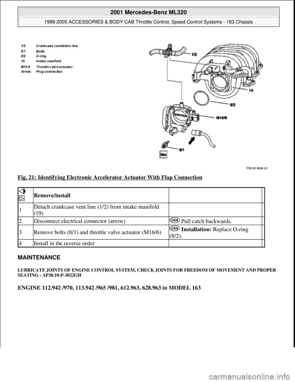
Fig. 21: Identifying Electronic Accelerator Actuator With Flap Connection
MAINTENANCE
LUBRICATE JOINTS OF ENGINE CONTROL SYSTEM, CHECK JOINTS FOR FREEDOM OF MOVEMENT AND PROPER
SEATING - AP30.10-P-3022GH
ENGINE 112.942 /970, 113.942 /965 /981, 612.963, 628.963 in MODEL 163
Remove/install
1Detach crankcase vent line (1/2) from intake manifold
(19)
2Disconnect electrical connector (arrow) Pull catch backwards.
3Remove bolts (8/1) and throttle valve actuator (M16/6) Installation: Replace O-ring
(8/2).
4Install in the reverse order
2001 Mercedes-Benz ML320
1998-2005 ACCESSORIES & BODY CAB Throttle Control, Speed Control Systems - 163 Chassis
me
Saturday, October 02, 2010 3:36:28 PMPage 36 © 2006 Mitchell Repair Information Company, LLC.
Page 3877 of 4133
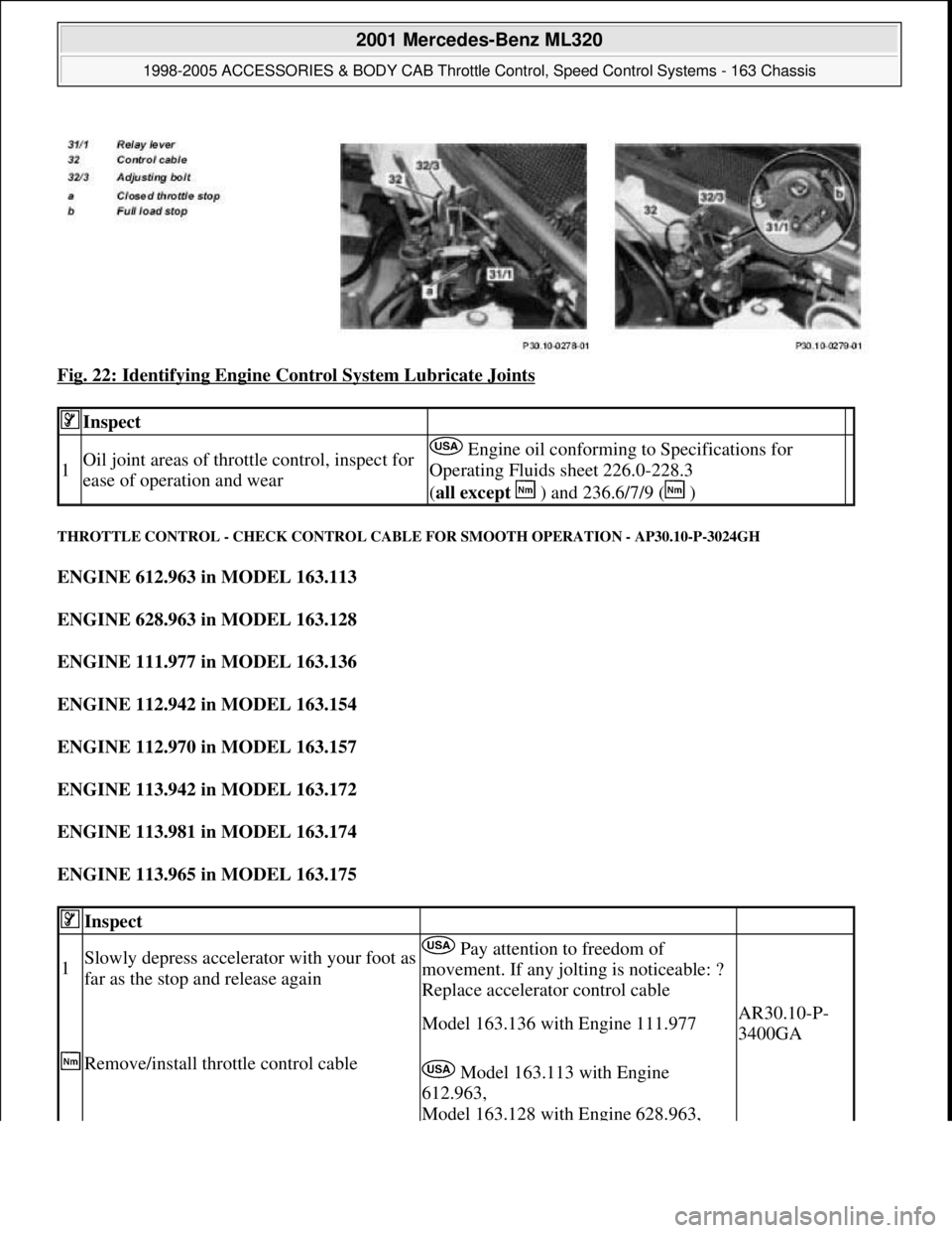
Fig. 22: Identifying Engine Control System Lubricate Joints
THROTTLE CONTROL - CHECK CONTROL CABLE FOR SMOOTH OPERATION - AP30.10-P-3024GH
ENGINE 612.963 in MODEL 163.113
ENGINE 628.963 in MODEL 163.128
ENGINE 111.977 in MODEL 163.136
ENGINE 112.942 in MODEL 163.154
ENGINE 112.970 in MODEL 163.157
ENGINE 113.942 in MODEL 163.172
ENGINE 113.981 in MODEL 163.174
ENGINE 113.965 in MODEL 163.175
Inspect
1Oil joint areas of throttle control, inspect for
ease of operation and wear Engine oil conforming to Specifications for
Operating Fluids sheet 226.0-228.3
(all except ) and 236.6/7/9 ( )
Inspect
1Slowly depress accelerator with your foot as
far as the stop and release again Pay attention to freedom of
movement. If any jolting is noticeable: ?
Replace accelerator control cable
Remove/install throttle control cable
Model 163.136 with Engine 111.977AR30.10-P-
3400GA
Model 163.113 with Engine
612.963,
Model 163.128 with Engine 628.963,
2001 Mercedes-Benz ML320
1998-2005 ACCESSORIES & BODY CAB Throttle Control, Speed Control Systems - 163 Chassis
me
Saturday, October 02, 2010 3:36:28 PMPage 37 © 2006 Mitchell Repair Information Company, LLC.
Page 3878 of 4133

Model 163.154 with Engine 112.942,
Model 163.157 with Engine 112.970,
Model 163.172 with Engine 113.942,
Model 163.174 with Engine 113.981,
Model 163.175 with Engine 113.965
AR30.10-P-
3400GI
2001 Mercedes-Benz ML320
1998-2005 ACCESSORIES & BODY CAB Throttle Control, Speed Control Systems - 163 Chassis
me
Saturday, October 02, 2010 3:36:28 PMPage 38 © 2006 Mitchell Repair Information Company, LLC.
Page 3879 of 4133
Page 3880 of 4133
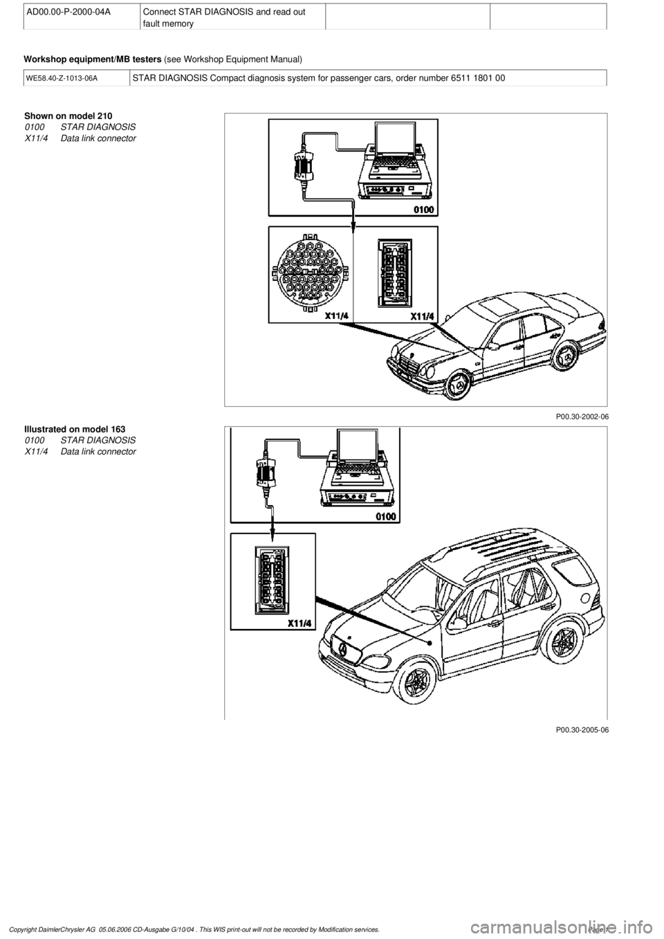
AD00.00-P-2000-04A
Connect STAR DIAGNOSIS and read out
fault memory
Workshop equipment/MB testers
(see Workshop Equipment Manual)
WE58.40-Z-1013-06A
STAR DIAGNOSIS Compact diagnosis system for passenger cars, order number 6511 1801 00
P00.30-2002-06
Shown on model 210
0100
STAR DIAGNOSIS
X11/4
Data link connector
P00.30-2005-06
Illustrated on model 163
0100
STAR DIAGNOSIS
X11/4
Data link connector
Copyright DaimlerChrysler AG 05.06.2006 CD-Ausgabe G/10/04 . This WIS print-out will not be recorde
d by Modification services.
Page 1