MERCEDES-BENZ ML430 1997 Complete Repair Manual
ML430 1997
MERCEDES-BENZ
MERCEDES-BENZ
https://www.carmanualsonline.info/img/4/57307/w960_57307-0.png
MERCEDES-BENZ ML430 1997 Complete Repair Manual
Trending: automatic transmission, lights, trip computer, power steering, hood open, oil temperature, jacking
Page 1231 of 4133
Operation
In selector lever position "P" and "N" the starter lockout contact (Y3/6s1) is actuated by a cam track which is
located on the detent plate. See Fig. 29
.
The permanent magnet (47) is moved away from the dry-reed contact (48). The dry-reed contact (48) is opened.
The ETC control module (N15/3) receives an electric signal. The circuit to the starter in the selector lever
position "P" and "N" is closed.
Torque Converter, Location/Task/Design/Function
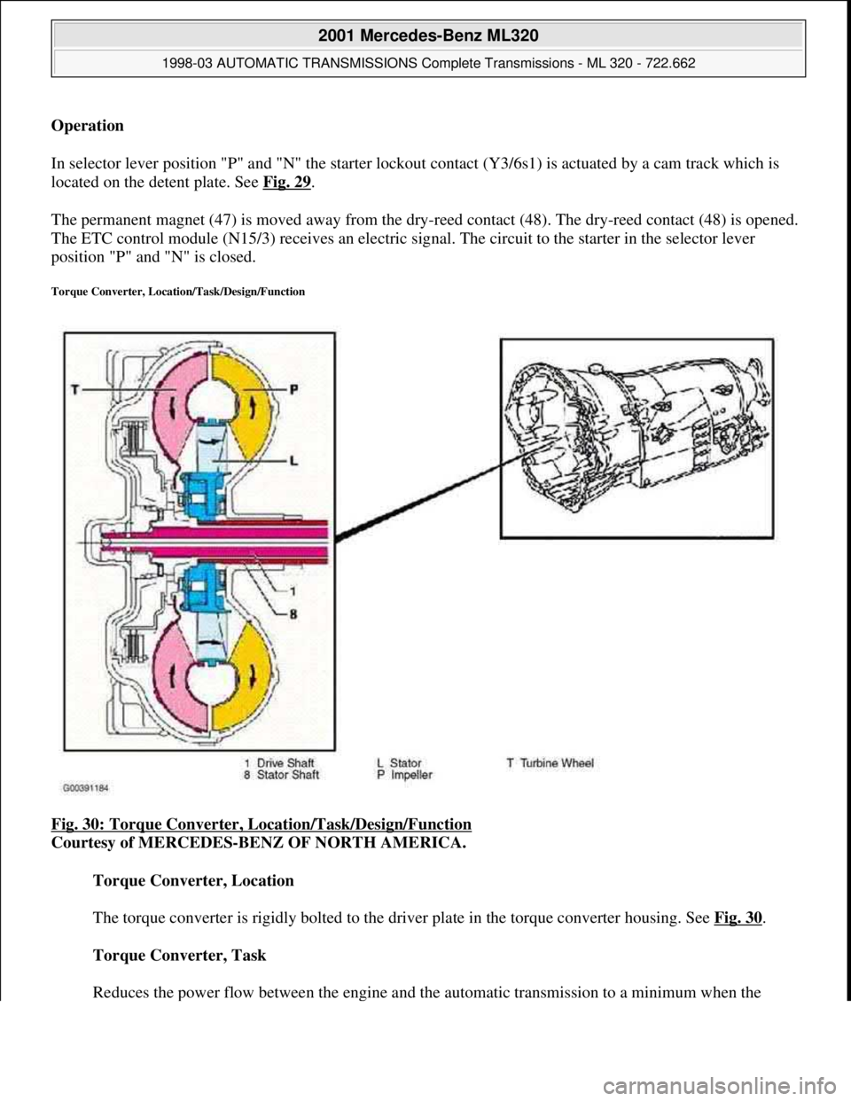
Fig. 30: Torque Converter, Location/Task/Design/Function
Courtesy of MERCEDES-BENZ OF NORTH AMERICA.
Torque Converter, Location
The torque converter is rigidly bolted to the driver plate in the torque converter housing. See Fig. 30
.
Torque Converter, Task
Reduces the power flow between the en
gine and the automatic transmission to a minimum when the
2001 Mercedes-Benz ML320
1998-03 AUTOMATIC TRANSMISSIONS Complete Transmissions - ML 320 - 722.662
me
Saturday, October 02, 2010 3:15:26 PMPage 62 © 2006 Mitchell Repair Information Company, LLC.
Page 1232 of 4133
vehicle is stationary and the engine is idling, boosts the engine torque and provides infinitely variable
engine speed and torque matching when moving off.
Torque Converter, Design
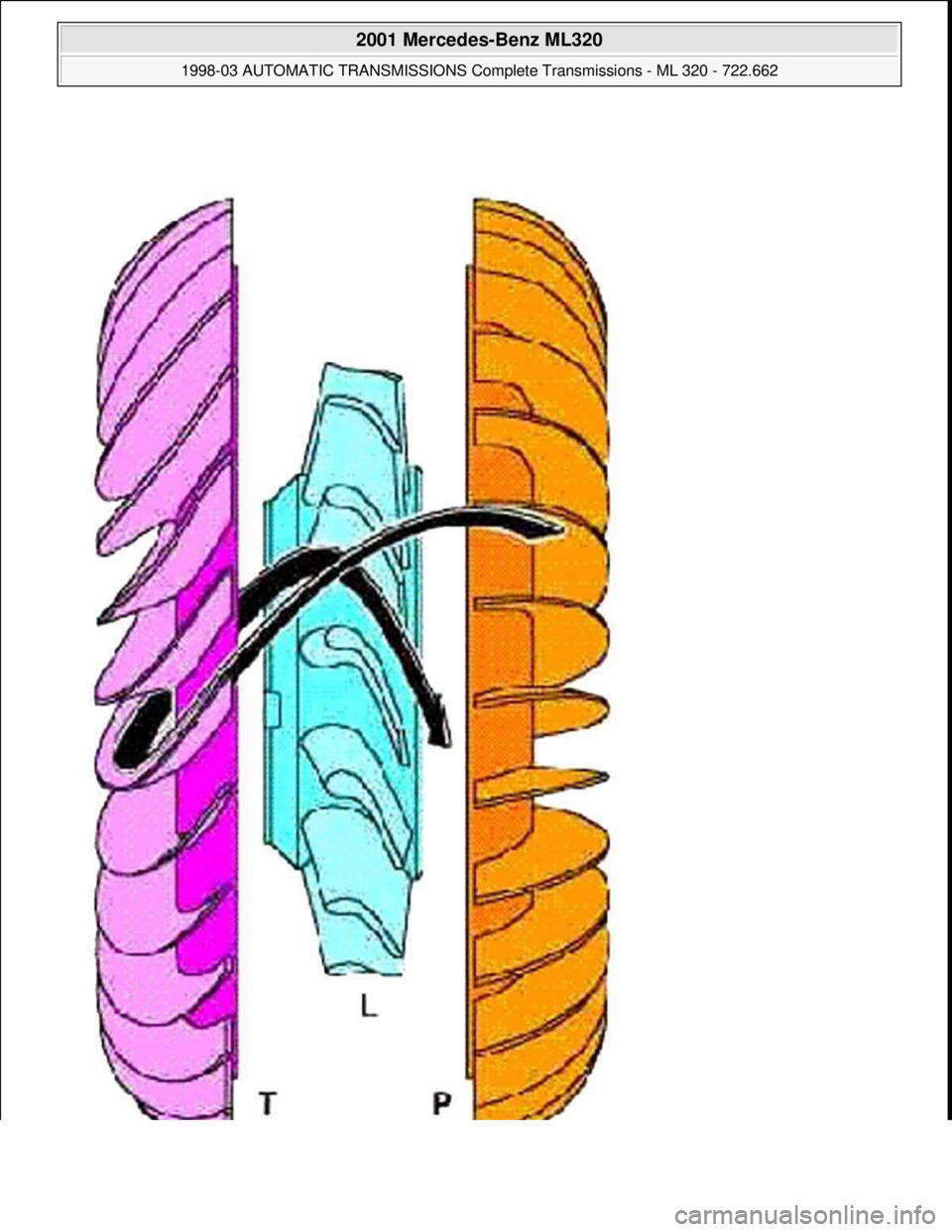
The impeller (P) is connected to the engine, the turbine wheel (T) is connected to the transmission input
shaft.
The stator (L) is connected to the transmission housing via a freewheel and the stator shaft (8).
Torque Converter, Function
See TORQUE CONVERTER, FUNCTION
.
Torque Converter, Function
Due to the effect of centrifugal force, the blades of the impeller (P) pump the oil outwards to the turbine wheel
(T), causing it to rotate. See Fig. 31
. The turbine wheel blades direct the oil onto the blades of the stator, which
in turn push the oil back to the impeller (P) (arrow). This diversion at the stator (L), which is supported against
the transmission housing via the freewheel, produces and increase in torque. At the maximum speed difference
between the impeller and the turbine wheel (T), the torque conversion achieves its maximum value at a factor of
1.8 to 2.0, dropping to a torque ratio of 1:1 as the speeds converge. From this operating state onwards, also
referred to as the coupling point, the stator (l) rotates with the impeller (P) and the turbine wheel (T).
Efficiencies of up to approximately 98% are achieved in the coupling range.
The oil in the torque converter is constantly being replaced so that the heat produced in the operating phase can
be dissipated via the transmission oil cooler.
2001 Mercedes-Benz ML320
1998-03 AUTOMATIC TRANSMISSIONS Complete Transmissions - ML 320 - 722.662
me
Saturday, October 02, 2010 3:15:26 PMPage 63 © 2006 Mitchell Repair Information Company, LLC.
Page 1233 of 4133
2001 Mercedes-Benz ML320
1998-03 AUTOMATIC TRANSMISSIONS Complete Transmissions - ML 320 - 722.662
me
Saturday, October 02, 2010 3:15:26 PMPage 64 © 2006 Mitchell Repair Information Company, LLC.
Page 1234 of 4133
Fig. 31: Torque Converter, Function
Courtesy of MERCEDES-BENZ OF NORTH AMERICA.
Wheel Speed Sensor, Location/Task/Function
2001 Mercedes-Benz ML320
1998-03 AUTOMATIC TRANSMISSIONS Complete Transmissions - ML 320 - 722.662
me
Saturday, October 02, 2010 3:15:26 PMPage 65 © 2006 Mitchell Repair Information Company, LLC.
Page 1235 of 4133
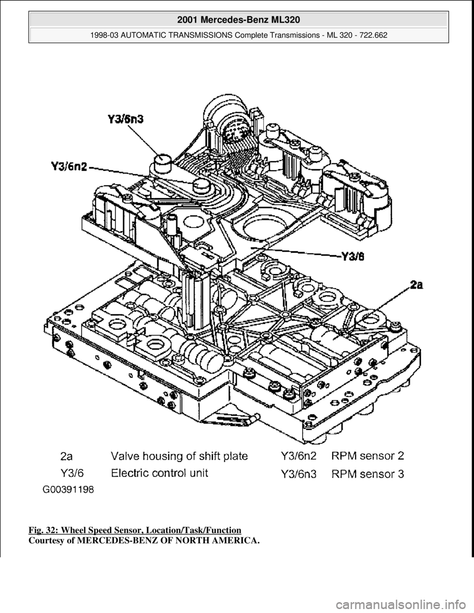
Fig. 32: Wheel Speed Sensor , Location/Task/Function
Courtesy of MERCEDES-BENZ OF NORTH AMERICA.
2001 Mercedes-Benz ML320
1998-03 AUTOMATIC TRANSMI SSIONS Complete Transmissions - ML 320 - 722.662
me
Saturday, October 02, 2010 3:15:26 PMPage 66 © 2006 Mitchell Repair Information Company, LLC.
Page 1236 of 4133
Wheel Speed Sensor, Location
RPM sensors 2 and 3 (Y3/6n2 and Y3/6n3) are permanently connected with the supporting body of the
electrical control unit (Y3/6) via contact tongues. See Fig. 32
.
Wheel Speed Sensor,
The signals from the RPM sensors 2 3 (Y3/6n2, Y3/6n3) are recorded in the ETC control module (N15/3)
together with the wheel and engine speeds and other information, and are the input signals for the
electronic control system.
Wheel Speed Sensor, Function
See SPEED SENSOR, FUNCTION
.
Speed Sensor, Function
2001 Mercedes-Benz ML320
1998-03 AUTOMATIC TRANSMISSIONS Complete Transmissions - ML 320 - 722.662
me
Saturday, October 02, 2010 3:15:26 PMPage 67 © 2006 Mitchell Repair Information Company, LLC.
Page 1237 of 4133
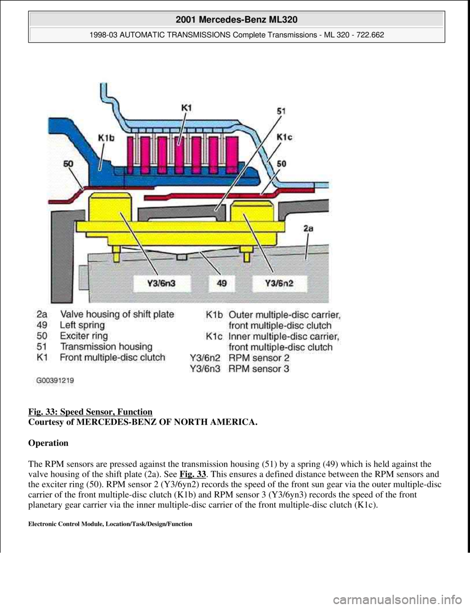
Fig. 33: Speed Sensor, Function
Courtesy of MERCEDES-BENZ OF NORTH AMERICA.
Operation
The RPM sensors are pressed against the transmission housing (51) by a spring (49) which is held against the
valve housing of the shift plate (2a). See Fig. 33
. This ensures a defined distance between the RPM sensors and
the exciter ring (50). RPM sensor 2 (Y3/6yn2) records the speed of the front sun gear via the outer multiple-disc
carrier of the front multiple-disc clutch (K1b) and RPM sensor 3 (Y3/6yn3) records the speed of the front
planetary gear carrier via the inner multiple-disc carrier of the front multiple-disc clutch (K1c).
Electronic Control Module, Location/Task/Design/Function
2001 Mercedes-Benz ML320
1998-03 AUTOMATIC TRANSMISSIONS Complete Transmissions - ML 320 - 722.662
me
Saturday, October 02, 2010 3:15:26 PMPage 68 © 2006 Mitchell Repair Information Company, LLC.
Page 1238 of 4133
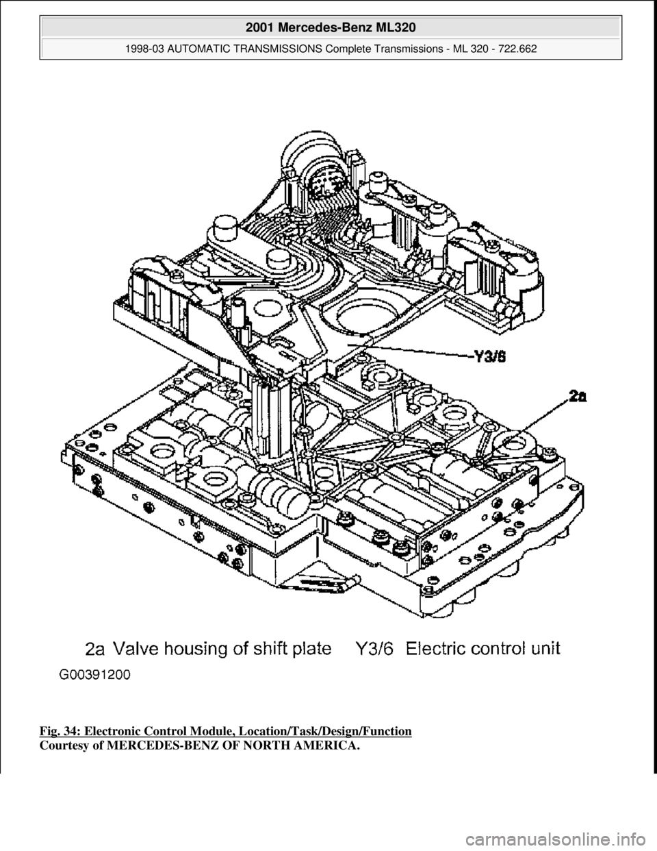
Fig. 34: Electronic Control Module, Location/Task/Design/Function
Courtesy of MERCEDES-BENZ OF NORTH AMERICA.
2001 Mercedes-Benz ML320
1998-03 AUTOMATIC TRANSMI SSIONS Complete Transmissions - ML 320 - 722.662
me
Saturday, October 02, 2010 3:15:26 PMPage 69 © 2006 Mitchell Repair Information Company, LLC.
Page 1239 of 4133
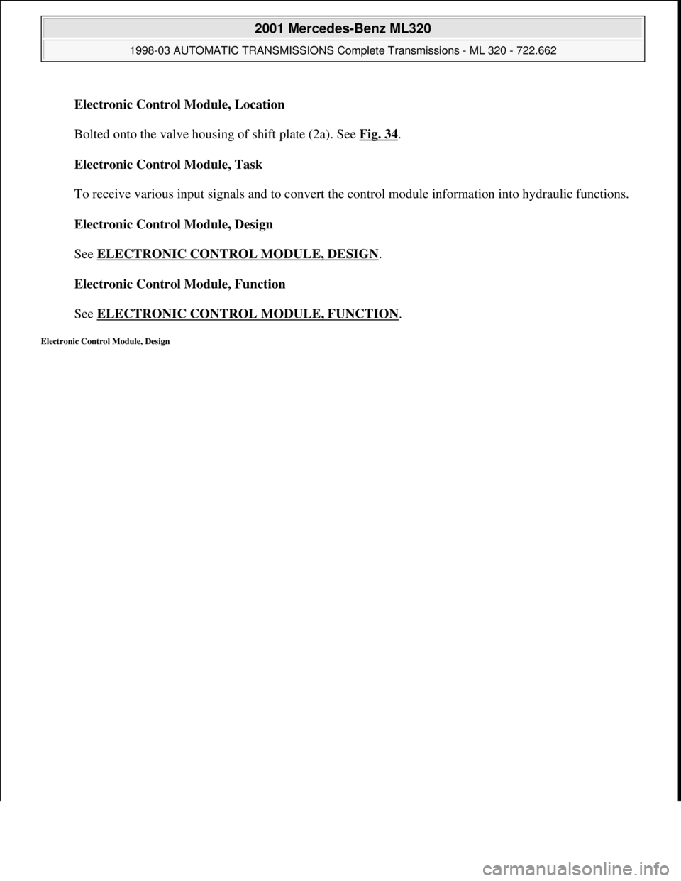
Electronic Control Module, Location
Bolted onto the valve housing of shift plate (2a). See Fig. 34
.
Electronic Control Module, Task
To receive various input signals and to convert the control module information into hydraulic functions.
Electronic Control Module, Design
See ELECTRONIC CONTROL MODULE, DESIGN
.
Electronic Control Module, Function
See ELECTRONIC CONTROL MODULE, FUNCTION
.
Electronic Control Module, Design
2001 Mercedes-Benz ML320
1998-03 AUTOMATIC TRANSMISSIONS Complete Transmissions - ML 320 - 722.662
me
Saturday, October 02, 2010 3:15:26 PMPage 70 © 2006 Mitchell Repair Information Company, LLC.
Page 1240 of 4133
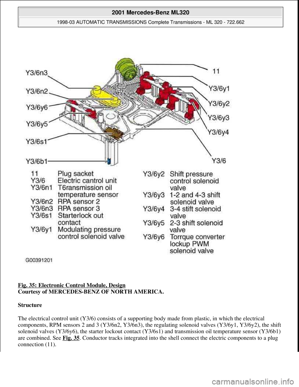
Fig. 35: Electronic Control Module, Design
Courtesy of MERCEDES-BENZ OF NORTH AMERICA.
Structure
The electrical control unit (Y3/6) consists of a supporting body made from plastic, in which the electrical
components, RPM sensors 2 and 3 (Y3/6n2, Y3/6n3), the regulating solenoid valves (Y3/6y1, Y3/6y2), the shift
solenoid valves (Y3/6y6), the starter lockout contact (Y3/6s1) and transmission oil temperature sensor (Y3/6b1)
are combined. See Fig. 35
. Conductor tracks integrated into the shell connect the electric components to a plug
connection (11).
2001 Mercedes-Benz ML320
1998-03 AUTOMATIC TRANSMISSIONS Complete Transmissions - ML 320 - 722.662
me
Saturday, October 02, 2010 3:15:26 PMPage 71 © 2006 Mitchell Repair Information Company, LLC.
Trending: catalytic converter, technical specifications, clutch, navigation, center console, check oil, alternator belt


