MERCEDES-BENZ ML430 1997 Complete Repair Manual
ML430 1997
MERCEDES-BENZ
MERCEDES-BENZ
https://www.carmanualsonline.info/img/4/57307/w960_57307-0.png
MERCEDES-BENZ ML430 1997 Complete Repair Manual
Trending: turn signal bulb, engine, coolant capacity, change key battery, check transmission fluid, coolant temperature, headlamp
Page 1281 of 4133
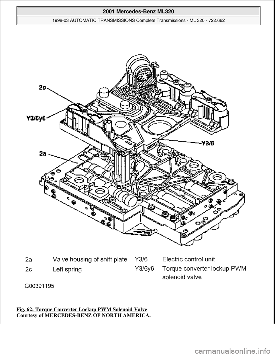
Fig. 62: Torque Converter Lockup PWM Solenoid Valve
Courtesy of MERCEDES-BENZ OF NORTH AMERICA.
2001 Mercedes-Benz ML320
1998-03 AUTOMATIC TRANSMI SSIONS Complete Transmissions - ML 320 - 722.662
me
Saturday, October 02, 2010 3:15:27 PMPage 112 © 2006 Mitchell Repair Information Company, LLC.
Page 1282 of 4133
Torque Converter Lockup PWM Solenoid Valve, Location
In the supporting body of the electrical control unit (Y3/6) and pressed against the valve housing of the
shift plate (2a) by means of a leaf spring (2c). See Fig. 62
.
Torque Converter Lockup PWM Solenoid Valve, Task
The PWM solenoid valve for the torque converter lockup (Y3/6y6) controls the pressure for the torque
converter lockup clutch.
Torque Converter Lockup PWM Solenoid Valve, Design
See TORQUE CONVERTER LOCKUP PWM SOLENOID VALVE, DESIGN
.
Torque Converter Lockup PWM Solenoid Valve, Function
it converts a pulse-width-modulated current actuated by the ETC control module (N15/3) into the
corresponding hydraulic pressure KUB (p-S/KUB).
Torque Converter Lockup PWM Solenoid Valve, Design
2001 Mercedes-Benz ML320
1998-03 AUTOMATIC TRANSMISSIONS Complete Transmissions - ML 320 - 722.662
me
Saturday, October 02, 2010 3:15:27 PMPage 113 © 2006 Mitchell Repair Information Company, LLC.
Page 1283 of 4133
2001 Mercedes-Benz ML320
1998-03 AUTOMATIC TRANSMISSIONS Complete Transmissions - ML 320 - 722.662
me
Saturday, October 02, 2010 3:15:27 PMPage 114 © 2006 Mitchell Repair Information Company, LLC.
Page 1284 of 4133
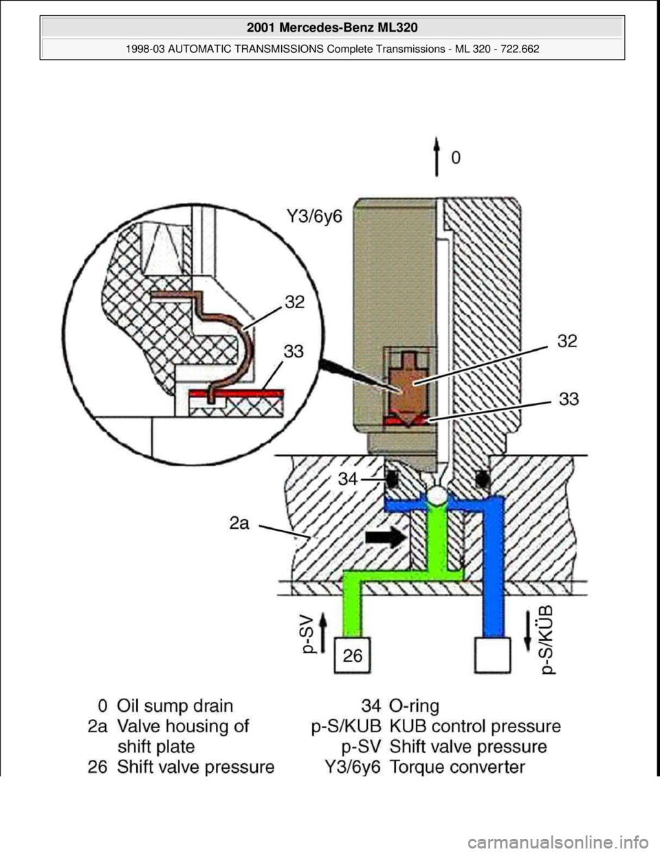
Fig. 63: Torque Converter Lockup Clutch PWM Solenoid Valve, Design
Courtesy of MERCEDES-BENZ OF NORTH AMERICA.
Structure - The torque converter lockup PWM solenoid valve (Y3/6y6) is sealed off to the valve body of the
shift plate (2a) by an O-ring (34) and a seal (arrow). See Fig. 63
. The contact springs (32) on the PWM
converter lockup solenoid valve (Y3/6y6) engage in a slot in the conductor tracks (33). The force of the contact
spring (32) ensures safe contacts.
Modulating Pressure Regulating Solenoid Valve, Location/Task/Design/Function
2001 Mercedes-Benz ML320
1998-03 AUTOMATIC TRANSMISSIONS Complete Transmissions - ML 320 - 722.662
me
Saturday, October 02, 2010 3:15:27 PMPage 115 © 2006 Mitchell Repair Information Company, LLC.
Page 1285 of 4133
2001 Mercedes-Benz ML320
1998-03 AUTOMATIC TRANSMI SSIONS Complete Transmissions - ML 320 - 722.662
me
Saturday, October 02, 2010 3:15:27 PMPage 116 © 2006 Mitchell Repair Information Company, LLC.
Page 1286 of 4133
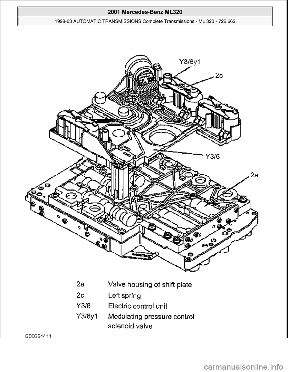
Fig. 64: Modulating Pressure Regulating Solenoid Valve, Location/Task/Design/Function
Courtesy of MERCEDES-BENZ OF NORTH AMERICA.
Modulating Pressure Regulating Solenoid Valve, Location
In the supporting body of the electrical control unit (Y3/6) and pressed against the valve housing of the
shift plate (2a) by means of a leaf spring. See Fig. 64
.
Modulating Pressure Regulating Solenoid Valve, Task
To control the modulating pressure depending on the constantly changing operating conditions such as
load/gear changes.
Modulating Pressure Regulating Solenoid Valve, Design
See MODULATING PRESSURE REGULATING SOLENOID VALVE, DESIGN
.
Modulating Pressure Regulating Solenoid Valve, Function
The modulating pressure regulating solenoid valve (Y3/6y1) assigns a proportional pressure to the current
which is controlled by the ETC control module (N15/3) according to the load.
Modulating Pressure Regulating Solenoid Valve, Design
2001 Mercedes-Benz ML320
1998-03 AUTOMATIC TRANSMISSIONS Complete Transmissions - ML 320 - 722.662
me
Saturday, October 02, 2010 3:15:27 PMPage 117 © 2006 Mitchell Repair Information Company, LLC.
Page 1287 of 4133
2001 Mercedes-Benz ML320
1998-03 AUTOMATIC TRANSMISSIONS Complete Transmissions - ML 320 - 722.662
me
Saturday, October 02, 2010 3:15:27 PMPage 118 © 2006 Mitchell Repair Information Company, LLC.
Page 1288 of 4133
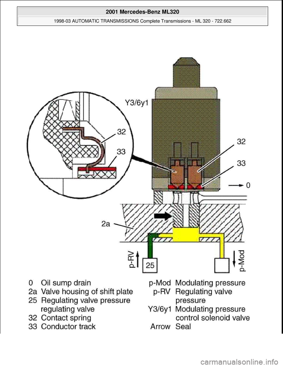
Fig. 65: Modulating Pressure Regulating Solenoid Valve
Courtesy of MERCEDES-BENZ OF NORTH AMERICA.
Structure - The modulating pressure regulating solenoid valve (Y3/6y1) had an interference fit and is sealed of
to the valve body of the shift plate (2a) by a seal (arrow). See Fig. 65
. The contact springs (32) on the
modulating pressure regulating solenoid valve (Y3/6y1) engage in a slot in the conductor tracks (33). The force
of the contact spring (32) ensures safe contacts.
Shift Pressure Regulating Solenoid Valve, Location/Task/Design/Function
2001 Mercedes-Benz ML320
1998-03 AUTOMATIC TRANSMISSIONS Complete Transmissions - ML 320 - 722.662
me
Saturday, October 02, 2010 3:15:27 PMPage 119 © 2006 Mitchell Repair Information Company, LLC.
Page 1289 of 4133
2001 Mercedes-Benz ML320
1998-03 AUTOMATIC TRANSMI SSIONS Complete Transmissions - ML 320 - 722.662
me
Saturday, October 02, 2010 3:15:27 PMPage 120 © 2006 Mitchell Repair Information Company, LLC.
Page 1290 of 4133
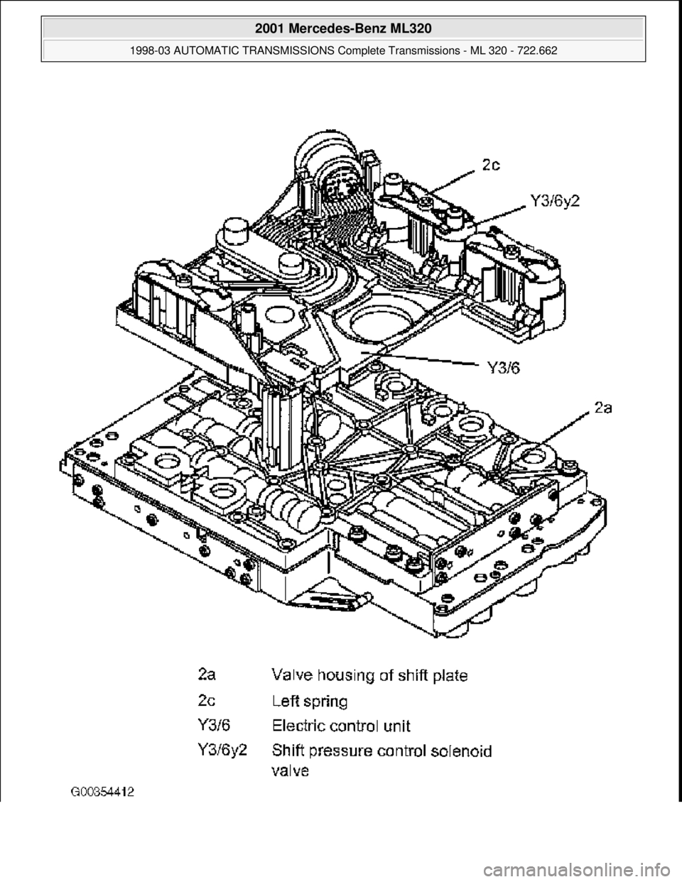
Fig. 66: Shift Pressure Regulating Solenoid Valve, Location/Task/Design/Function
Courtesy of MERCEDES-BENZ OF NORTH AMERICA.
Shift Pressure Regulating Solenoid Valve, Location
In the supporting body of the electrical control unit (Y3/6) and pressed against the valve housing of the
shift plate (2a) by means of a leaf spring. See Fig. 66
.
Shift Pressure Regulating Solenoid Valve, Task
To control the shift pressure depending on the constantly changing operating conditions, such as
load/gear changes.
Shift Pressure Regulating Solenoid Valve, Design
See SHIFT PRESSURE REGULATING SOLENOID VALVE, DESIGN
.
Shift Pressure Regulating Solenoid Valve, Function
The shift pressure regulating solenoid valve (Y3/6y2) assigns a proportional pressure to the current which
is controlled by the ETC control module (N15/3) according to the load.
Shift Pressure Regulating Valve, Location/Task/Function
2001 Mercedes-Benz ML320
1998-03 AUTOMATIC TRANSMISSIONS Complete Transmissions - ML 320 - 722.662
me
Saturday, October 02, 2010 3:15:27 PMPage 121 © 2006 Mitchell Repair Information Company, LLC.
Trending: bulb, remote start, gas mileage, ignition, child restraint, child seat, fuse box location
