MERCEDES-BENZ ML430 1997 Complete Repair Manual
Manufacturer: MERCEDES-BENZ, Model Year: 1997, Model line: ML430, Model: MERCEDES-BENZ ML430 1997Pages: 4133, PDF Size: 88.89 MB
Page 2601 of 4133

1.1
Unscrew bolts at rear of 2/3 seat bench and
raise rear of seat bench
Up to VIN A145272, X708318.
1.2
Remove covers at seat frame of 60% bench
seat
As of VIN A145273, X708319.
AR91.12-P-1100GH
Only remove the covers which are
identified in the document with A, D and E.
2.1
Fold 60% bench seat forward into footwell
As of VIN A145273, X708319. See
operator's manual.
3.1
Pull floor covering below rear seat mounting
bracket (1) of 60% seat forward
Carefully pull floor covering forward under
the seat console to prevent it from tearing.
As of VIN A145273, X708319.
4.1
Pull the floor covering forward under the front
corner of the left C-pillar cover (2)
Carefully pull the floor covering forward
under the cover to prevent it from tearing.
As of VIN A145273, X708319.
5
Cut into floor covering directly behind seat
retaining cable (3)
Ensure that the wiring harness (4) is not
damaged when cutting the floor covering.
As of VIN A145273, X708319. Broken
line marks the cut.
6
Fold floor mat back
Do not crease floor mat!
Fold floor mat back far enough to provide
access to cap (84) between body and fuel
pump.
7
Remove end cover (84) of body
Installation:
Replace cap and insert with
new sealing compound.
Cap (84) is sealed in with body sealer.
Heat with hot air blower to make it easier to
remove.
8
Seal fuel return line (90/11)
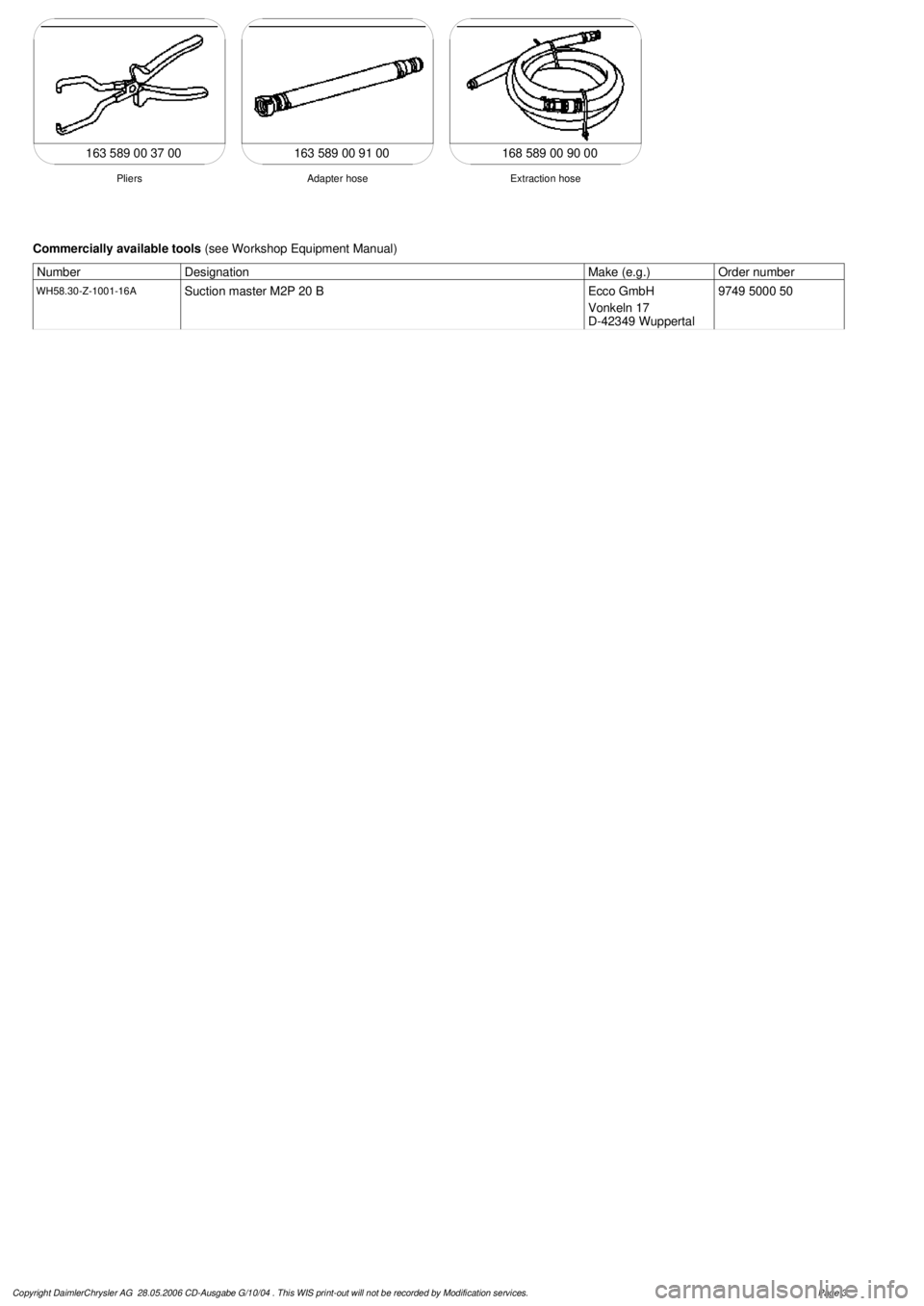
Pliers
*163589003700
9
Connect extraction hose (90/14) with adapter
hose to connection for fuel return line (90/11)
Extraction hose
*168589009000
Adapter hose
*163589009100
10
Connect ground cable (90/10) of extraction
pump ground terminal vehicle battery
Pumping out
11
Pump fuel out into safety container using
extraction pump
*BF47.10-P-1001-01A
*WH58.30-Z-1001-16A
12
Install in the reverse order
Fuel tank
Number
Designation
Models
163.113/
136/154/
172 up to
31.08.01
Models
163.113/
136/154/
172 as of
01.09.01
Models
163.157/
175
Model
163.128
Model
163.174
BF47.10-P-1001-01A
Fuel tank capacity
Total capacity
Liter
72838393
Reserve capacity
Liter
10121212
Copyright DaimlerChrysler AG 28.05.2006 CD-Ausgabe G/10/04 . This WIS print-out will not be recorde
d by Modification services.
Page 2
Page 2602 of 4133

163 589 00 91 00
Extraction hose
Adapter hose
Pliers
163 589 00 37 00 168 589 00 90 00
Commercially available tools
(see Workshop Equipment Manual)
Number
Designation
Make (e.g.)
Order number
WH58.30-Z-1001-16A
Suction master M2P 20 B
Ecco GmbH
Vonkeln 17
D-42349 Wuppertal
9749 5000 50
Copyright DaimlerChrysler AG 28.05.2006 CD-Ausgabe G/10/04 . This WIS print-out will not be recorde
d by Modification services.
Page 3
Page 2603 of 4133

BF47.10-P-1000-01A
Fuel tank capacity
Model 124, 129, 140, 163, 168, 170,
171, 199, 202, 203, 208, 209, 210, 211,
215, 220, 230, 240,
414, 463
i
Modification notes
26.4.04
Value modified from 87.6 Nm to 97 Nm
Value modified in series 1001 for model 199
Fuel tank
Number
Designation
Model
124.008/019/
022/028/
029/032/040/
042/052
Model
124.07/
08/09
Model
124.034/
036
Model
124 with
increased tank
capacity code
915
BF47.10-P-1001-01A
Fuel tank capacity
Total capacity
Liters
70729090
Reserve capacity
Liters
99
11
11.5
Fuel tank
Number
Designation
Model
124.06
Model
129
Model
140
without
code
282a or
code 308
Model
140 with code
282a
or
code 308
Model
163.113/
136/154/
172 up to
31.08.01
BF47.10-P-1001-01A
Fuel tank capacity
Total capacity
Liters
70801009072
Reserve capacity
Liters
1110
12.512.5
10
Fuel tank
Number
Designation
Model
163.113/
136/154/
172 as of
01.09.01
Model
163.157/
175
Model
163.128
Model
163.174
Model
168.006/
007/ 008/
009/131/
132/133
Model
168.031/
032/033
BF47.10-P-1001-01A
Fuel tank capacity
Total capacity
Liters
8383935454
Reserve capacity
Liters
121212
88
Designation
Model
170.43/
445/447/46
Model
170.444/
449
Model
171
Model
199
Model
202.018/020/023/
024/025/026 /
029/033/078 /
080/082/083 /
085/086/089/093
BF47.10-P-1001-01A
Fuel tank capacity
Total capacity
Liters
536070
87,6
62
Reserve capacity
Liters
789
10
8
Copyright DaimlerChrysler AG 28.05.2006 CD-Ausgabe G/10/04 . This WIS print-out will not be recorde
d by Modification services.
Page 1
Page 2604 of 4133

Fuel tank
Number
Designation
Model
202.121/122/128/
133/180/182/
188/193
Model
203
Model
208
Model
209
BF47.10-P-1001-01A
Fuel tank capacity
Total capacity
Liters
62626262
Reserve capacity
Liters
7888
Designation
Model
210 with
code 282a
or
code 308
Model
210.0
without code
915
Model
210.0
with code
915
Models
210.2/6
BF47.10-P-1001-01A
Fuel tank capacity
Total capacity
Liters
70658070
Reserve capacity
Liters
98
10
9
Designation
Model
211.004/006/042/606
without code 915 (fuel
tank with increased
capacity)
Model
211.004/006/016/042/
061/080/206/216/242/
261/280/606/616
with code 915 (fuel
tank with increased
capacity)
BF47.10-P-1001-01A
Fuel tank capacity
Total capacity
Liters
6580
Reserve capacity
Liters
8...98...9
Fuel tank
Number
Designation
Model
211.016/061/080/616
without code
915 (fuel tank with
increased capacity),
954a (Avantgarde),
955a (Elegance)
Model
211.016/061/080/
216/261/280 /616
with code 954a
(Avantgarde),
955a (Elegance)
Model
211.023/026/
028/065/070/
076/082/083/
223/226/265/
270/276/282/
283
BF47.10-P-1001-01A
Fuel tank capacity
Total capacity
Liters
658080
Reserve capacity
Liters
8...98...98...9
Fuel tank
Copyright DaimlerChrysler AG 28.05.2006 CD-Ausgabe G/10/04 . This WIS print-out will not be recorde
d by Modification services.
Page 2
Page 2605 of 4133

Number
Designation
Model
211.206
without code 915 (fuel
tank with increased
capacity)
Model
211.216/242/
261/280
without code 915 (fuel
tank with increased
capacity),
954a (Avantgarde),
955a (Elegance)
BF47.10-P-1001-01A
Fuel tank capacity
Total capacity
Liters
7070
Reserve capacity
Liters
8...98...9
Fuel tank
Number
Designation
Model
215 with
code 282a
or
code 308
Model
215
without
code
282a or
code 308
Model
220 with
code 282a
or
code 308
BF47.10-P-1001-01A
Fuel tank capacity
Total capacity
Liters
788878
Reserve capacity
Liters
101110
Fuel tank
Number
Designation
Model
220
without
code
282a or
code 308
Model
230
Model
240
Model
414
Model
461, 463
BF47.10-P-1001-01A
Fuel tank capacity
Total capacity
Liters
88801105496
Reserve capacity
Liters
111014
8
20
Copyright DaimlerChrysler AG 28.05.2006 CD-Ausgabe G/10/04 . This WIS print-out will not be recorde
d by Modification services.
Page 3
Page 2606 of 4133

AR47.10-P-4001GH
Emptying, filling the fuel tank
11.3.97
Model
163.136 with engine 111.977
Model
163.154 with engine 112.942
Model
163.157 with engine 112.970
Model
163.172 with engine 113.942
Model
163.174 with engine 113.981
Model
163.175 with engine 113.965
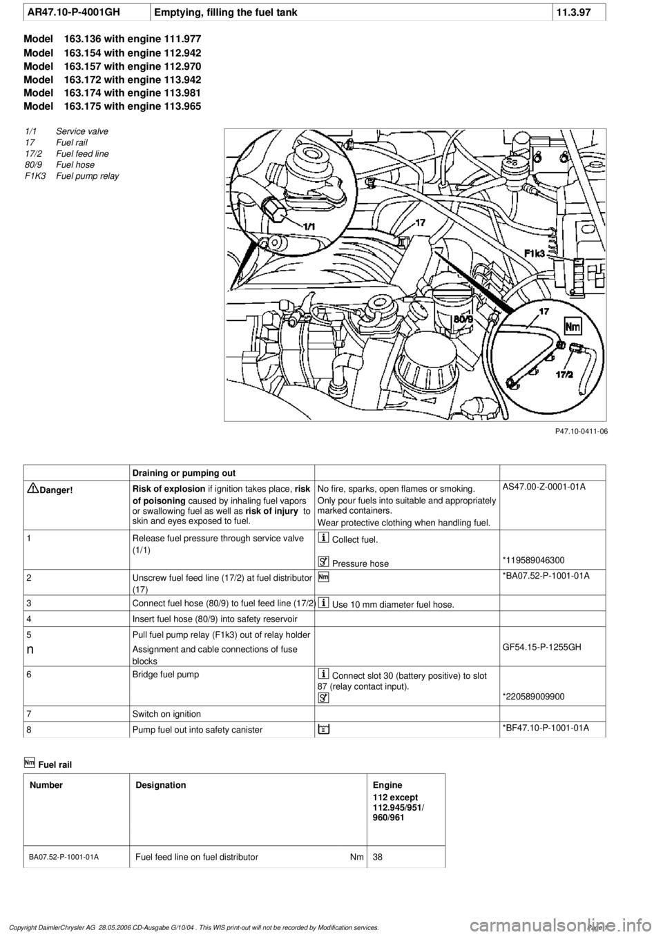
P47.10-0411-06
1/1
Service valve
17
Fuel rail
17/2
Fuel feed line
80/9
Fuel hose
F1K3
Fuel pump relay
Draining or pumping out
Danger!
Risk of explosion
if ignition takes place,
risk
of poisoning
caused by inhaling fuel vapors
or swallowing fuel as well as
risk of injury
to
skin and eyes exposed to fuel.
No fire, sparks, open flames or smoking.
Only pour fuels into suitable and appropriately
marked containers.
Wear protective clothing when handling fuel.
AS47.00-Z-0001-01A
1
Release fuel pressure through service valve
(1/1)
Collect fuel.
Pressure hose
*119589046300
2
Unscrew fuel feed line (17/2) at fuel distributor
(17)
*BA07.52-P-1001-01A
3
Connect fuel hose (80/9) to fuel feed line (17/2)
Use 10 mm diameter fuel hose.
4
Insert fuel hose (80/9) into safety reservoir
5
Pull fuel pump relay (F1k3) out of relay holder
n
Assignment and cable connections of fuse
blocks
GF54.15-P-1255GH
6
Bridge fuel pump
Connect slot 30 (battery positive) to slot
87 (relay contact input).
*220589009900
7
Switch on ignition
8
Pump fuel out into safety canister
*BF47.10-P-1001-01A
Fuel rail
Number
Designation
Engine
112 except
112.945/951/
960/961
BA07.52-P-1001-01A
Fuel feed line on fuel distributor
Nm
38
Copyright DaimlerChrysler AG 28.05.2006 CD-Ausgabe G/10/04 . This WIS print-out will not be recorde
d by Modification services.
Page 1
Page 2607 of 4133

Fuel rail
Number
Designation
Engines
113.940/941/
942/943/944/
945/946/948/
960/961/962/
963/965/966/
967/968/969/
980/981/982/
984/986/988/
BA07.52-P-1001-01A
Fuel feed line on fuel distributor
Nm
38
Fuel tank
Number
Designation
Models
163.113/
136/154/
172 up to
31.08.01
Models
163.113/
136/154/
172 as of
01.09.01
Models
163.157/
175
Model
163.174
BF47.10-P-1001-01A
Fuel tank capacity
Total capacity
Liters
728393
Reserve capacity
Liters
101212
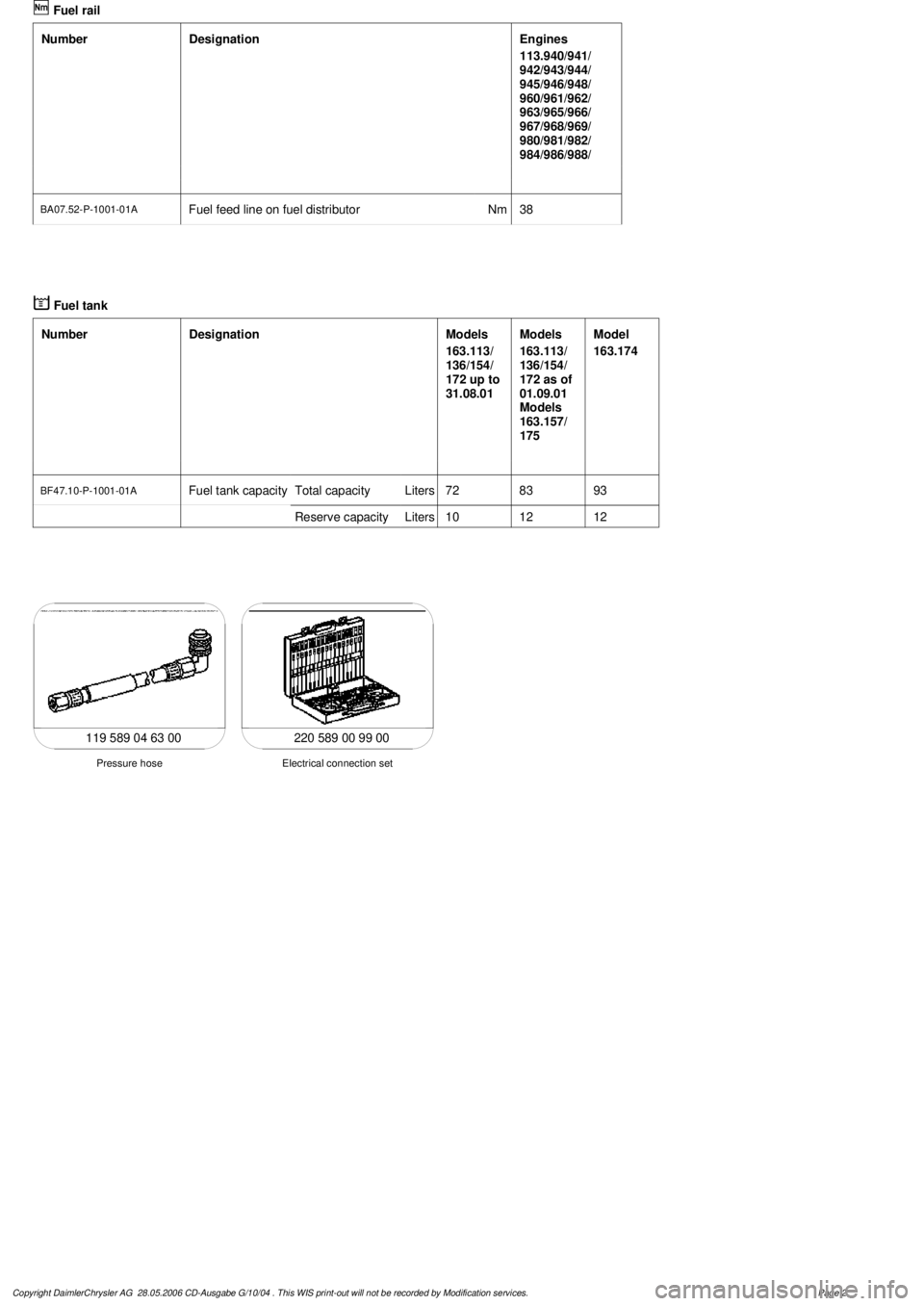
220 589 00 99 00
Electrical connection set
Pressure hose
119 589 04 63 00
Copyright DaimlerChrysler AG 28.05.2006 CD-Ausgabe G/10/04 . This WIS print-out will not be recorde
d by Modification services.
Page 2
Page 2608 of 4133

AR47.10-P-4100GH
Remove fuel tank
10.3.97
MODEL
163.113 with ENGINE 612.963
MODEL
163.128 with ENGINE 628.963
MODEL
163.136 with ENGINE 111.977
MODEL
163.154 with ENGINE 112.942
MODEL
163.157 with ENGINE 112.970
MODEL
163.172 with ENGINE 113.942
MODEL
163.175 with ENGINE 113.965
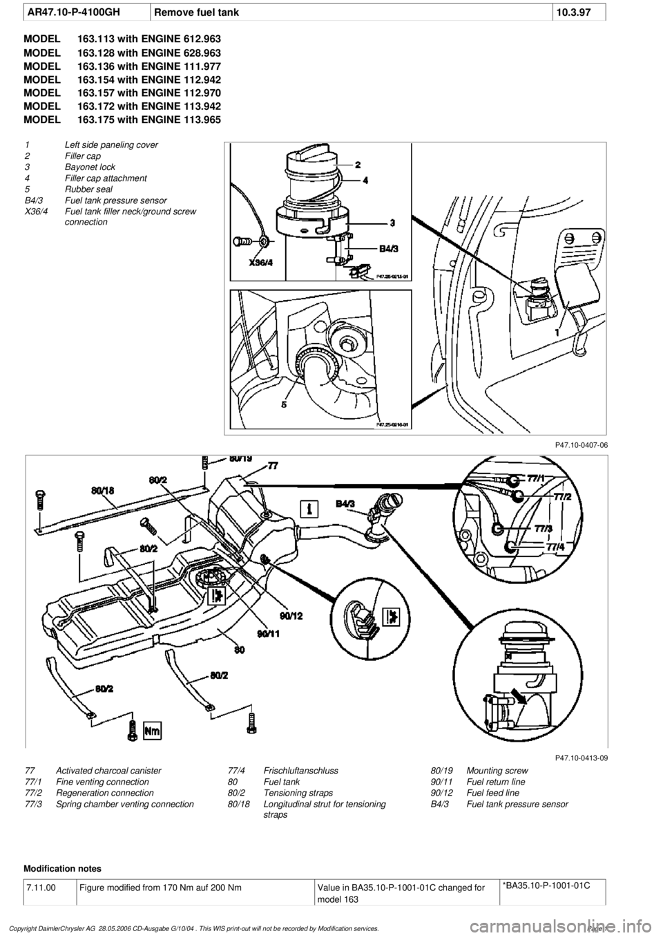
P47.10-0407-06
1
Left side paneling cover
2
Filler cap
3
Bayonet lock
4
Filler cap attachment
5
Rubber seal
B4/3 Fuel tank pressure sensor
X36/4
Fuel tank filler neck/ground screw
connection
P47.10-0413-09
77
Activated charcoal canister
77/1
Fine venting connection
77/2
Regeneration connection
77/3
Spring chamber venting connection
80/19
Mounting screw
90/11
Fuel return line
90/12
Fuel feed line
B4/3 Fuel tank pressure sensor
77/4
Frischluftanschluss
80
Fuel tank
80/2
Tensioning straps
80/18
Longitudinal strut for tensioning
straps
Modification notes
7.11.00
Figure modified from 170 Nm auf 200 Nm
Value in BA35.10-P-1001-01C changed for
model 163
*BA35.10-P-1001-01C
Copyright DaimlerChrysler AG 28.05.2006 CD-Ausgabe G/10/04 . This WIS print-out will not be recorde
d by Modification services.
Page 1
Page 2609 of 4133

Remove, Install
Danger!
Risk of explosion
from fuel igniting,
risk of
poisoning
from inhaling and swallowing fuel
as well as
risk of injury
to eyes and skin
from contact with fuel.
Fire, sparks, open flames or smoking
forbidden.
Pour fuels only into suitable and appropriately
marked containers.
Wear protective clothing when handling fuel.
AS47.00-Z-0001-01A
1
Drain fuel tank
Via fuel pump. NOT for model 163.113/128.
AR47.10-P-4001GH
If fuel pump faulty, and model 163.113/128.
AR47.10-P-4000GH
*BF47.10-P-1001-01A
2
Unscrew filler cap (2) and detach from filler
cap attachment (4)
3.1
Remove left seat of 3rd seat row
If installed. See owner's manual
4
Unclip cover of left-hand side panel (1)
5.1
Detach fuel lines of expansion reservoir and
separate from filler neck
As of VIN A289565. NOT for model
163.113/128.
6
Detach fuel filler neck from guide funnel
Installation:
Check O-ring and replace if
necessary. Ensure that the bayonet-lock
remains above
the pressure sensor.
Ensure it is correctly located when installed.
Open bayonet lock (3) to do this.
7
Pull filler neck through toward interior
Screw on cap again in order to avoid fuel
flowing out.
8.1
Remove fuel tank pressure sensor (B4/3)
Only USA version
AR47.10-P-8022GH
9.1
Detach bolted connection of fuel tank filler
neck/ground (X36/4) from filler neck
NOT for model 163.113/128.
10.1
Cut cable strap for retaining clips of fuel lines
at filler neck and remove retaining clips
As of VIN A289565. NOT for model
163.113/128.
Danger!
Risk of fatal accident
from vehicle slipping
or toppling off the lift platform
Align vehicle between the columns of lifting
platform and position the four support plates
below the support strongpoints specified by
the vehicle manufacturer.
AS00.00-Z-0010-01A
11
Place the vehicle on lifting platform
AR00.60-P-1000GH
12
Separate rubber seal (5) from underside of
vehicle and remove filler neck from interior
Do not damage fuel lines at filler neck.
13
Remove left rear wheel
e
Removing and installing wheels, rotating if
necessary
AP40.10-P-4050GH
14
Remove spare wheel and spare wheel carrier
complete
NOT in the case of spare wheel
holder/spare wheel, code 849.
15
Cut a large safety cable strap for filler neck at
bracket on longitudinal frame member
16
Remove bracket from longitudinal frame
member
17
Disconnect connection for regeneration (77/2)
and fresh air connection (77/4) on activated
charcoal canister (77)
Installation
: Connect up lines as per
connection diagram:
#
Engine 111
AR47.30-P-8212-01GJ
Engines 112, 113
AR47.30-P-8212-01GI
Engines 112, 113 version
I
AR47.30-P-8212-01GH
Charcoal canister and fuel tank form a
single unit.
NOT for model 163.113/128.
18
Detach vent hose
At rear differential to rear of activated
charcoal reservoir.
19
Remove rear exhaust system heat shield.
Do not damage boot at rear axle shaft.
20
Disconnect rear propeller shaft at differential
Installation:
Install new self-locking bolts.
Tie up propeller shaft e.g. using welding
wire
Heat bolts with hot air fan to facilitate
removing. Mark propeller shaft and differential
gear flange for correct installed position.
*BA41.10-P-1002-01C
Copyright DaimlerChrysler AG 28.05.2006 CD-Ausgabe G/10/04 . This WIS print-out will not be recorde
d by Modification services.
Page 2
Page 2610 of 4133

21
Detach rear brake cables
Unclip at underfloor of vehicle and
unscrew brake cable holder on right and left
at frame.
22.1
Unbolt check strap of rear axle carrier from
underfloor of vehicle
As of VIN A145273, X708319.
23
Remove left rear stone shield
24
Remove lower tensioning straps (80/2) and
loosen the upper tensioning straps
Tensioning straps are color-coded and
cannot be mixed up.
Support fuel tank using assembly jack.
*BA47.10-P-1001-01D
25
Remove longitudinal strut for tensioning
straps (80/18)
*BA47.10-P-1002-01D
26.1
Unscrew linkage for headlamp range
adjustment
at the top
If installed.
27
Unscrew nuts on bottom of the shock
absorbers at the transverse control arm
Installation:
Install new self-locking nuts.
*BA32.25-P-1001-03D
28
Unscrew rear axle carrier from floor of vehicle
and lower as far as possible
Support rear axle carrier.
Installation:
Install new self-locking bolts.
*BA35.10-P-1001-01C
29
Lower fuel tank
Support fuel tank.
30
Remove upper tensioning strap
at the rear
The tensioning strap at the top at the front.
31.1
Unclip lines from side of fuel tank
As of VIN A289565, X754620.
Installation:
The lines must not be
damaged.
32
Disconnect fuel pump electrical plug
connection
33
Disconnect fuel feed line (90/12) and fuel
return line (90/11)
Fuel lines must not be bent.
Pliers
*163589003700
34
Remove fuel tank (80)
Installation:
Ensure that the sealing
rubbers (5) seat correctly in the body floor to
prevent water entry.
Do not damage fuel lines at filler neck.
Guide filler neck with its chamfered side
(arrow) through between frame and body.
Filler neck and fuel tank cannot be separated
from each other.
35
Install in the reverse order
36.1
Dispose of fuel tank
Ony when replacing the fuel tank.
o
Disposal of fuel tanks
OS47.10-P-0001-01A
Rear axle carrier
Number
Designation
Model
Series 163
BA35.10-P-1001-01C
Self-locking bolt, rear axle carrier at front and rear
to frame floor
Nm
200
Propeller shaft
Number
Designation
Model
Series 163
BA41.10-P-1002-01C
Self-locking bolt, rear propsharft
at rear axle center section
Nm
50
Copyright DaimlerChrysler AG 28.05.2006 CD-Ausgabe G/10/04 . This WIS print-out will not be recorde
d by Modification services.
Page 3