MERCEDES-BENZ ML430 1997 Complete Repair Manual
Manufacturer: MERCEDES-BENZ, Model Year: 1997, Model line: ML430, Model: MERCEDES-BENZ ML430 1997Pages: 4133, PDF Size: 88.89 MB
Page 271 of 4133
221 Malfunction and indicator lamps
Te ch n ica l
data Instruments
and controlsOperation DrivingInstrument
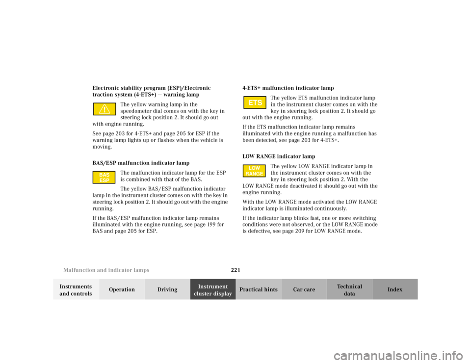
cluster displayPractical hints Car care Index Electronic stability program (ESP)/Electronic
traction system (4-ETS+) — warning lamp
The yellow warning lamp in the
speedometer dial comes on with the key in
steering lock position 2. It should go out
with engine running.
See page 203 for 4-ETS+ and page 205 for ESP if the
warning lamp lights up or flashes when the vehicle is
moving.
BAS/ESP malfunction indicator lamp
The malfunction indicator lamp for the ESP
is combined with that of the BAS.
The yellow BAS / ESP malfunction indicator
lamp in the instrument cluster comes on with the key in
steering lock position 2. It should go out with the engine
running.
If the BAS / ESP malfunction indicator lamp remains
illuminated with the engine running, see page 199 for
BAS and page 205 for ESP.4-ETS+ malfunction indicator lamp
The yellow ETS malfunction indicator lamp
in the instrument cluster comes on with the
key in steering lock position 2. It should go
out with the engine running.
If the ETS malfunction indicator lamp remains
illuminated with the engine running a malfunction has
been detected, see page 203 for 4-ETS+.
LOW RANGE indicator lamp
The yellow LOW RANGE indicator lamp in
the instrument cluster comes on with the
key in steering lock position 2. With the
LOW RANGE mode deactivated it should go out with the
engine running.
With the LOW RANGE mode activated the LOW RANGE
indicator lamp is illuminated continuously.
If the indicator lamp blinks fast, one or more switching
conditions were not observed, or the LOW RANGE mode
is defective, see page 209 for LOW RANGE mode.
BAS
ESP
ETSLOW
RANGE
Page 272 of 4133
222 Malfunction and indicator lamps
Te ch n ica l
data Instruments
and controlsOperation DrivingInstrument
cluster displayPractical hints Car care Index
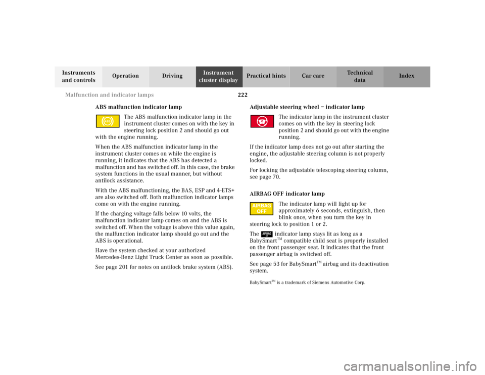
ABS malfunction indicator lamp
The ABS malfunction indicator lamp in the
instrument cluster comes on with the key in
steering lock position 2 and should go out
with the engine running.
When the ABS malfunction indicator lamp in the
instrument cluster comes on while the engine is
running, it indicates that the ABS has detected a
malfunction and has switched off. In this case, the brake
system functions in the usual manner, but without
antilock assistance.
With the ABS malfunctioning, the BAS, ESP and 4-ETS+
are also switched off. Both malfunction indicator lamps
come on with the engine running.
If the charging voltage falls below 10 volts, the
malfunction indicator lamp comes on and the ABS is
switched off. When the voltage is above this value again,
the malfunction indicator lamp should go out and the
ABS is operational.
Have the system checked at your authorized
Mercedes-Benz Light Truck Center as soon as possible.
See page 201 for notes on antilock brake system (ABS).Adjustable steering wheel – indicator lamp
The indicator lamp in the instrument cluster
comes on with the key in steering lock
position 2 and should go out with the engine
running.
If the indicator lamp does not go out after starting the
engine, the adjustable steering column is not properly
locked.
For locking the adjustable telescoping steering column,
see page 70.
AIRBAG OFF indicator lamp
The indicator lamp will light up for
approximately 6 seconds, extinguish, then
blink once, when you turn the key in
steering lock to position 1 or 2.
The 7 indicator lamp stays lit as long as a
BabySmart
TM compatible child seat is properly installed
on the front passenger seat. It indicates that the front
passenger airbag is switched off.
See page 53 for BabySmart
TM airbag and its deactivation
system.
BabySmart
TM is a trademark of Siemens Automotive Corp.
ABS
Page 273 of 4133
223 Malfunction and indicator lamps
Te ch n ica l
data Instruments
and controlsOperation DrivingInstrument
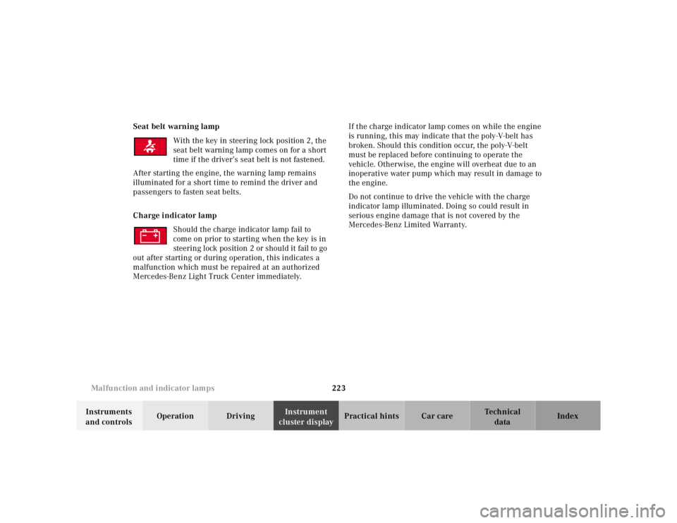
cluster displayPractical hints Car care Index Seat belt warning lamp
With the key in steering lock position 2, the
seat belt warning lamp comes on for a short
time if the driver’s seat belt is not fastened.
After starting the engine, the warning lamp remains
illuminated for a short time to remind the driver and
passengers to fasten seat belts.
Charge indicator lamp
Should the charge indicator lamp fail to
come on prior to starting when the key is in
steering lock position 2 or should it fail to go
out after starting or during operation, this indicates a
malfunction which must be repaired at an authorized
Mercedes-Benz Light Truck Center immediately.If the charge indicator lamp comes on while the engine
is running, this may indicate that the poly-V-belt has
broken. Should this condition occur, the poly-V-belt
must be replaced before continuing to operate the
vehicle. Otherwise, the engine will overheat due to an
inoperative water pump which may result in damage to
the engine.
Do not continue to drive the vehicle with the charge
indicator lamp illuminated. Doing so could result in
serious engine damage that is not covered by the
Mercedes-Benz Limited Warranty.
Page 274 of 4133
224 Malfunction and indicator lamps
Te ch n ica l
data Instruments
and controlsOperation DrivingInstrument
cluster displayPractical hints Car care Index
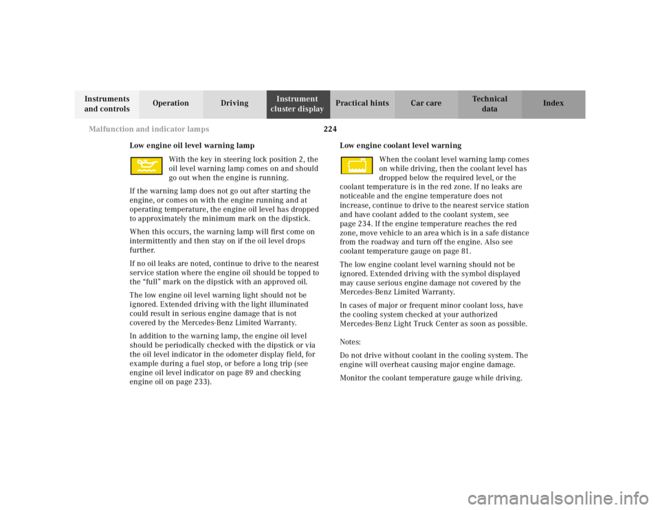
Low engine oil level warning lamp
With the key in steering lock position 2, the
oil level warning lamp comes on and should
go out when the engine is running.
If the warning lamp does not go out after starting the
engine, or comes on with the engine running and at
operating temperature, the engine oil level has dropped
to approximately the minimum mark on the dipstick.
When this occurs, the warning lamp will first come on
intermittently and then stay on if the oil level drops
further.
If no oil leaks are noted, continue to drive to the nearest
service station where the engine oil should be topped to
the “full” mark on the dipstick with an approved oil.
The low engine oil level warning light should not be
ignored. Extended driving with the light illuminated
could result in serious engine damage that is not
covered by the Mercedes-Benz Limited Warranty.
In addition to the warning lamp, the engine oil level
should be periodically checked with the dipstick or via
the oil level indicator in the odometer display field, for
example during a fuel stop, or before a long trip (see
engine oil level indicator on page 89 and checking
engine oil on page 233).Low engine coolant level warning
When the coolant level warning lamp comes
on while driving, then the coolant level has
dropped below the required level, or the
coolant temperature is in the red zone. If no leaks are
noticeable and the engine temperature does not
increase, continue to drive to the nearest service station
and have coolant added to the coolant system, see
page 234. If the engine temperature reaches the red
zone, move vehicle to an area which is in a safe distance
from the roadway and turn off the engine. Also see
coolant temperature gauge on page 81.
The low engine coolant level warning should not be
ignored. Extended driving with the symbol displayed
may cause serious engine damage not covered by the
Mercedes-Benz Limited Warranty.
In cases of major or frequent minor coolant loss, have
the cooling system checked at your authorized
Mercedes-Benz Light Truck Center as soon as possible.
Notes:
Do not drive without coolant in the cooling system. The
engine will overheat causing major engine damage.
Monitor the coolant temperature gauge while driving.
Page 275 of 4133
225 Malfunction and indicator lamps
Te ch n ica l
data Instruments
and controlsOperation DrivingInstrument
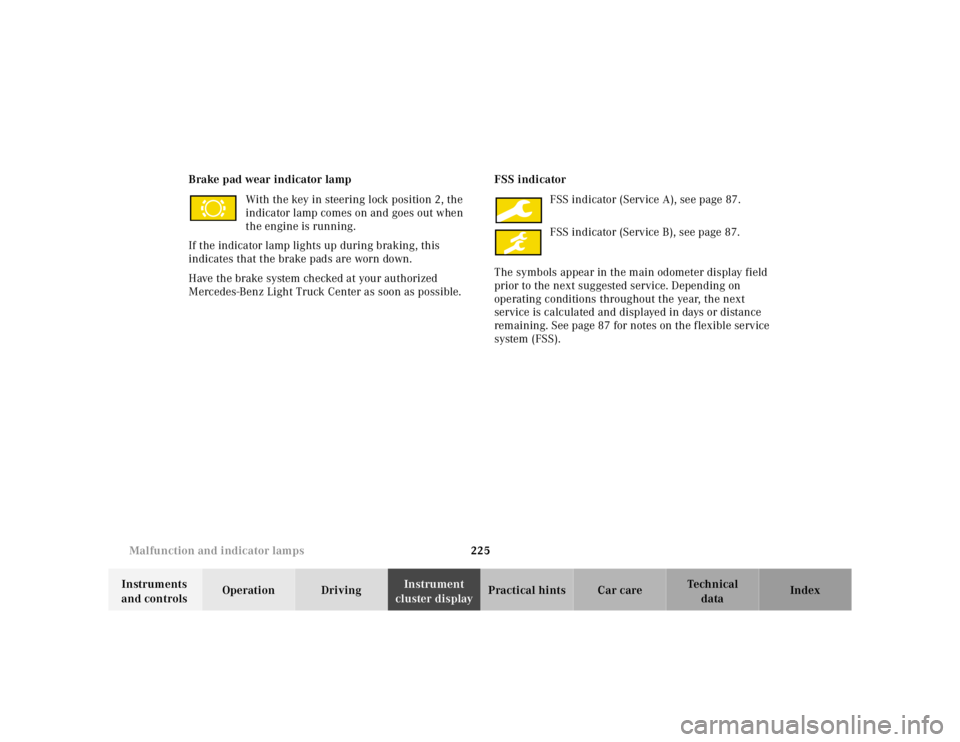
cluster displayPractical hints Car care Index Brake pad wear indicator lamp
With the key in steering lock position 2, the
indicator lamp comes on and goes out when
the engine is running.
If the indicator lamp lights up during braking, this
indicates that the brake pads are worn down.
Have the brake system checked at your authorized
Mercedes-Benz Light Truck Center as soon as possible.FSS indicator
FSS indicator (Service A), see page 87.
FSS indicator (Service B), see page 87.
The symbols appear in the main odometer display field
prior to the next suggested service. Depending on
operating conditions throughout the year, the next
service is calculated and displayed in days or distance
remaining. See page 87 for notes on the flexible service
system (FSS).
Page 276 of 4133

Page 277 of 4133
227 Contents - Practical hints
Te ch n ica l
data Instruments
and controlsOperation DrivingInstrument
cluster displayPractical hintsCar care Index
Practical hintsFirst aid kit .....................................228
Fuses ................................................228
Electrical outlet ..............................230
Stowing things in the vehicle ......230
Hood ................................................. 231
Checking engine oil level .............233
Automatic transmission
fluid level ...................................234
Engine oil consumption ................234
Coolant level ...................................234
Adding coolant ...........................235
Windshield washer/headlamp
cleaning system .........................236
Windshield and
headlamp washer fluid
mixing ratio ................................237Vehicle jack, wheel bolt
wrench and screwdriver ......... 237
Air pump ......................................... 239
Wheels ............................................ 240
Tire replacement ....................... 240
Rotating wheels ......................... 241
Spare wheel .................................... 242
Changing wheels ........................... 245
Tire inflation pressure ................. 250
Battery ............................................. 251
Jump starting ................................. 253
Towing the vehicle ........................ 255
Transmission selector lever,
manually unlocking .................. 259
Stranded vehicle ............................ 259Exterior lamps ................................260
Headlamp assembly ................... 261
Taillamp assemblies ..................265
Adjusting headlamp aim ...............268
Remote control
battery replacement .................270
Synchronizing
remote control ............................ 271
Emergency operation of
sliding/pop-up roof ...................272
Emergency operation of
Skyview Top ...............................273
Manual release for
fuel filler flap ............................. 274
Replacing wiper blades .................275
Roof rack ......................................... 276
Page 278 of 4133
228 First aid kit
Te ch n ica l
data Instruments
and controlsOperation DrivingInstrument
cluster displayPractical hintsCar care Index
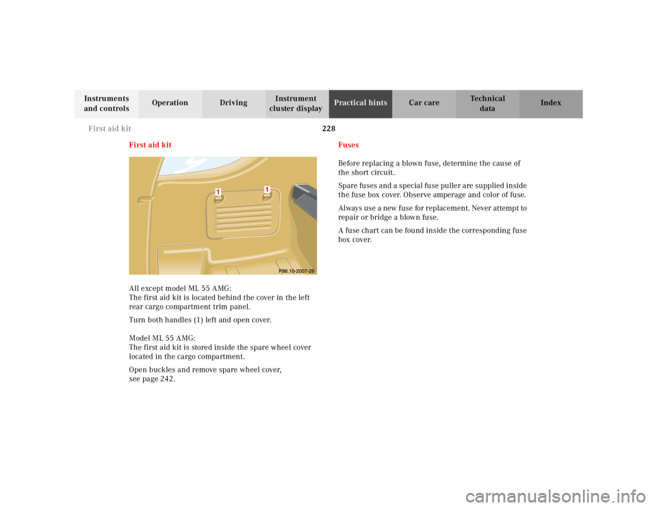
First aid kit
All except model ML 55 AMG:
The first aid kit is located behind the cover in the left
rear cargo compartment trim panel.
Turn both handles (1) left and open cover.
Model ML 55 AMG:
The first aid kit is stored inside the spare wheel cover
located in the cargo compartment.
Open buckles and remove spare wheel cover,
see page 242.Fuses
Before replacing a blown fuse, determine the cause of
the short circuit.
Spare fuses and a special fuse puller are supplied inside
the fuse box cover. Observe amperage and color of fuse.
Always use a new fuse for replacement. Never attempt to
repair or bridge a blown fuse.
A fuse chart can be found inside the corresponding fuse
box cover.
Page 279 of 4133
229 Fuses
Te ch n ica l
data Instruments
and controlsOperation DrivingInstrument
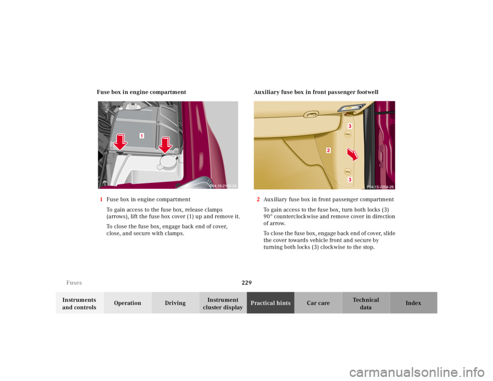
cluster displayPractical hintsCar care Index Fuse box in engine compartment
1Fuse box in engine compartment
To gain access to the fuse box, release clamps
(arrows), lift the fuse box cover (1) up and remove it.
To close the fuse box, engage back end of cover,
close, and secure with clamps.Auxiliary fuse box in front passenger footwell
2Auxiliary fuse box in front passenger compartment
To gain access to the fuse box, turn both locks (3)
90° counterclockwise and remove cover in direction
of arrow.
To close the fuse box, engage back end of cover, slide
the cover towards vehicle front and secure by
turning both locks (3) clockwise to the stop.
1
Page 280 of 4133
230 Electrical outlet
Te ch n ica l
data Instruments
and controlsOperation DrivingInstrument
cluster displayPractical hintsCar care Index
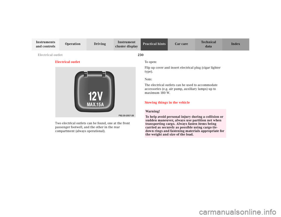
Electrical outlet
Two electrical outlets can be found, one at the front
passenger footwell, and the other in the rear
compartment (always operational).To o p e n :
Flip up cover and insert electrical plug (cigar lighter
type).
Note:
The electrical outlets can be used to accommodate
accessories (e.g. air pump, auxiliary lamps) up to
maximum 180 W.
Stowing things in the vehicle
Wa r n i n g !
To help avoid personal injury during a collision or
sudden maneuver, always use partition net when
transporting cargo. Always fasten items being
carried as securely as possible using cargo tie-
down rings and fastening materials appropriate for
the weight and size of the load.