MERCEDES-BENZ ML430 1997 Complete Repair Manual
Manufacturer: MERCEDES-BENZ, Model Year: 1997, Model line: ML430, Model: MERCEDES-BENZ ML430 1997Pages: 4133, PDF Size: 88.89 MB
Page 3501 of 4133
AR68.10-P-1030GH
Remove/install center section of instrument panel
11.4.97
MODEL
163.113 /128 /136 /154 /157 /172 /174 /175
P68.10-2358-06
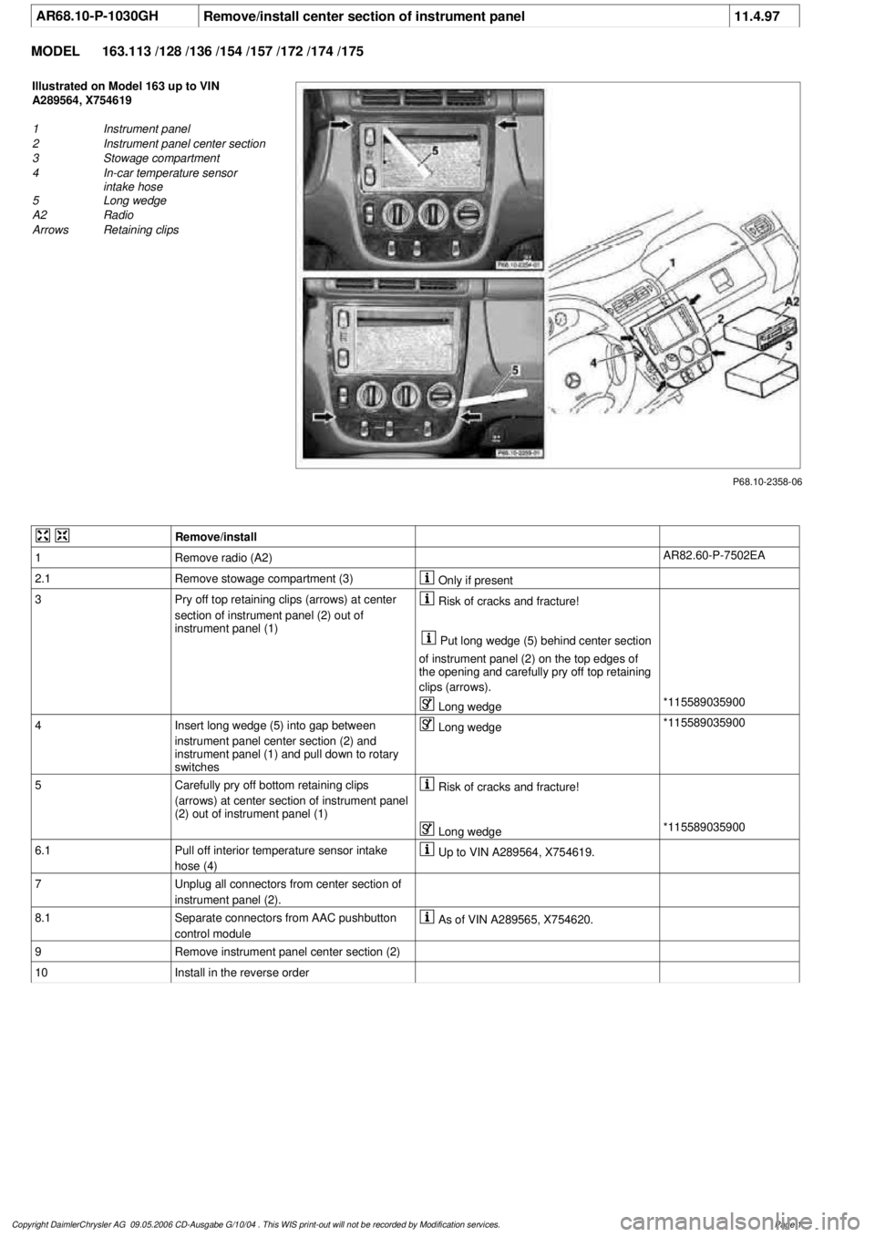
Illustrated on Model 163 up to VIN
A289564, X754619
1
Instrument panel
2
Instrument panel center section
3
Stowage compartment
4
In-car temperature sensor
intake hose
5
Long wedge
A2
Radio
Arrows
Retaining clips
Remove/install
1
Remove radio (A2)
AR82.60-P-7502EA
2.1
Remove stowage compartment (3)
Only if present
3
Pry off top retaining clips (arrows) at center
section of instrument panel (2) out of
instrument panel (1)
Risk of cracks and fracture!
Put long wedge (5) behind center section
of instrument panel (2) on the top edges of
the opening and carefully pry off top retaining
clips (arrows).
Long wedge
*115589035900
4
Insert long wedge (5) into gap between
instrument panel center section (2) and
instrument panel (1) and pull down to rotary
switches
Long wedge
*115589035900
5
Carefully pry off bottom retaining clips
(arrows) at center section of instrument panel
(2) out of instrument panel (1)
Risk of cracks and fracture!
Long wedge
*115589035900
6.1
Pull off interior temperature sensor intake
hose (4)
Up to VIN A289564, X754619.
7
Unplug all connectors from center section of
instrument panel (2).
8.1
Separate connectors from AAC pushbutton
control module
As of VIN A289565, X754620.
9
Remove instrument panel center section (2)
10
Install in the reverse order
Copyright DaimlerChrysler AG 09.05.2006 CD-Ausgabe G/10/04 . This WIS print-out will not be recorde
d by Modification services.
Page 1
Page 3502 of 4133
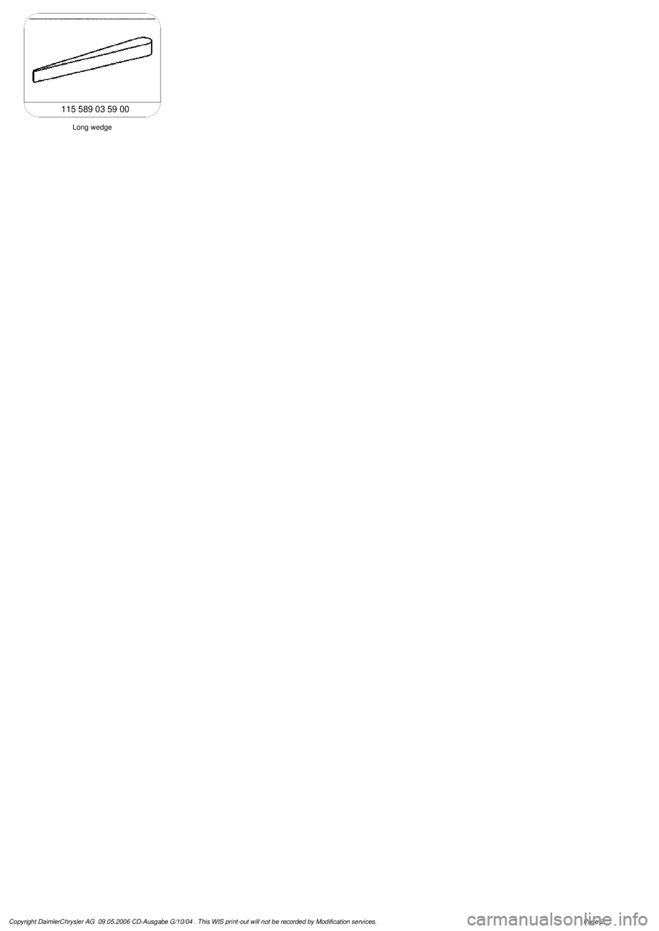
Long wedge
115 589 03 59 00
Copyright DaimlerChrysler AG 09.05.2006 CD-Ausgabe G/10/04 . This WIS print-out will not be recorde
d by Modification services.
Page 2
Page 3503 of 4133
AR54.25-P-2800GH
Removing and installing combination switch
21.1.97
MODEL
163.113 /128 /136 /154 /157 /172 /174 /175
P54.25-0325-06
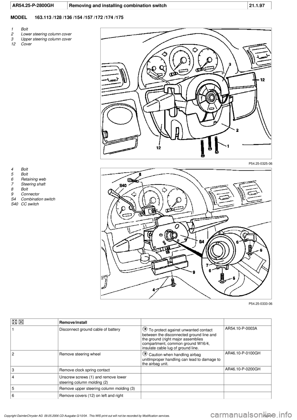
1
Bolt
2
Lower steering column cover
3
Upper steering column cover
12
Cover
P54.25-0333-06
4
Bolt
5
Bolt
6
Retaining web
7
Steering shaft
8
Bolt
9
Connector
S4
Combination switch
S40
CC switch
Remove/install
1
Disconnect ground cable of battery
To protect against unwanted contact
between the disconnected ground line and
the ground (right major assemblies
compartment, common ground W16/4,
insulate cable lug of ground line.
AR54.10-P-0003A
2
Remove steering wheel
Caution when handling airbag
unitImproper handling can lead to damage to
the airbag unit.
AR46.10-P-0100GH
3
Remove clock spring contact
AR46.10-P-0200GH
4
Unscrew screws (1) and remove lower
steering column molding (2)
5
Remove upper steering column molding (3)
6
Remove covers (12) on left and right
Copyright DaimlerChrysler AG 09.05.2006 CD-Ausgabe G/10/04 . This WIS print-out will not be recorde
d by Modification services.
Page 1
Page 3504 of 4133

7.1
Disconnect electrical connectors at the covers
12)
Only with left/right folding outside mirror,
code 500 and headlamp cleaning system,
code 600.
8
Unscrew screw (4) and disconnect connector
(9)
9
Unscrew screw (8) and remove cruise control
switch (S40)
10
Unscrew screws (5)
11
Pull combination switch (S4) off the retaining
webs (6) and remove
12
Install in the reverse order
13
Perform function check
Copyright DaimlerChrysler AG 09.05.2006 CD-Ausgabe G/10/04 . This WIS print-out will not be recorde
d by Modification services.
Page 2
Page 3505 of 4133
AR68.10-P-1500GH
Removing and installing cover below instrument panel (left)
4.2.97
MODELS
163.113 /128 /136 /154 /157 /172 /174 /175
P68.10-0522-06
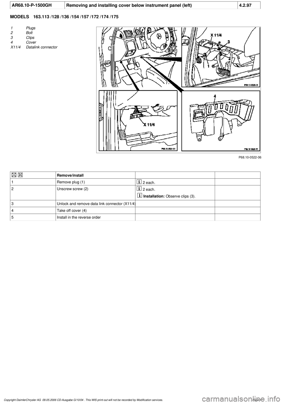
1
Plugs
2
Bolt
3
Clips
4
Cover
X11/4
Datalink connector
Remove/install
1
Remove plug (1)
2 each.
2
Unscrew screw (2)
2 each.
Installation:
Observe clips (3).
3
Unlock and remove data link connector (X11/4)
4
Take off cover (4)
5
Install in the reverse order
Copyright DaimlerChrysler AG 09.05.2006 CD-Ausgabe G/10/04 . This WIS print-out will not be recorde
d by Modification services.
Page 1
Page 3506 of 4133
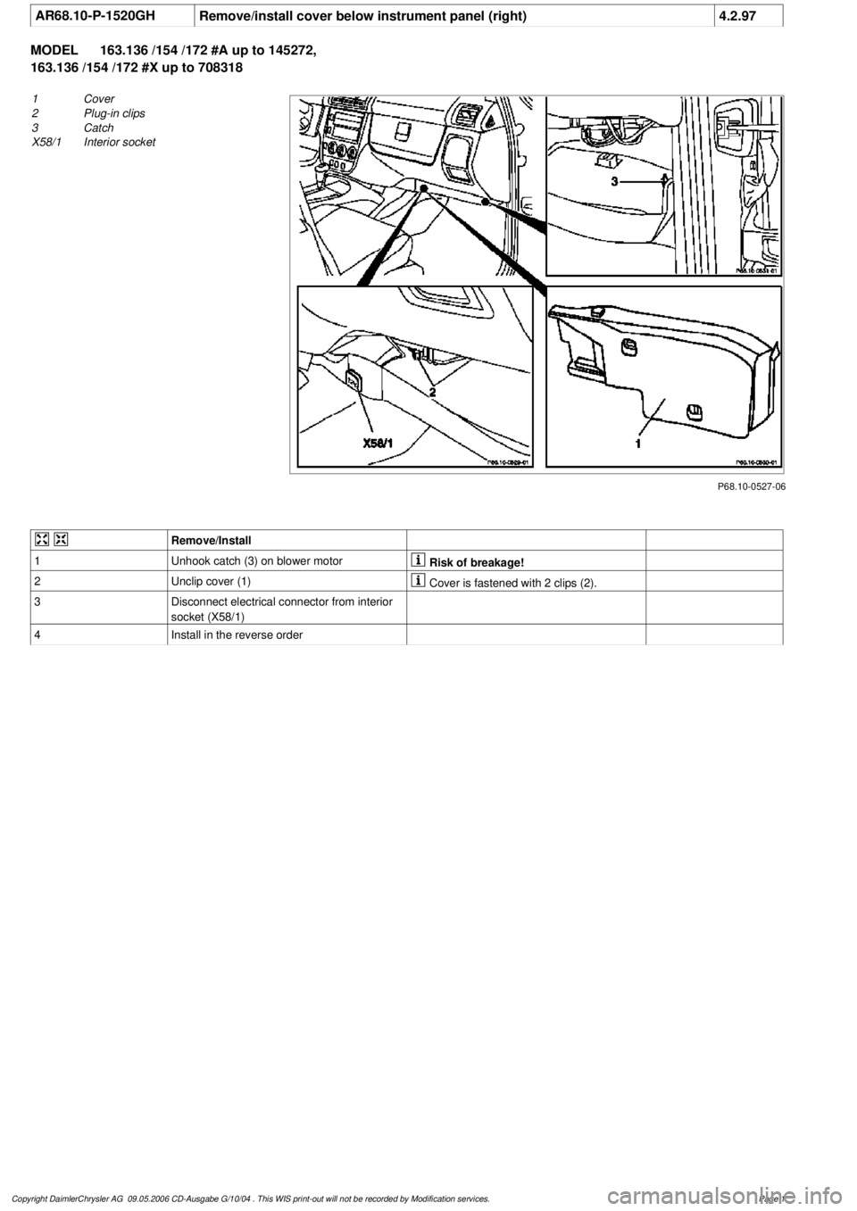
AR68.10-P-1520GH
Remove/install cover below instrument panel (right)
4.2.97
MODEL
163.136 /154 /172 #A up to 145272,
163.136 /154 /172 #X up to 708318
P68.10-0527-06
1
Cover
2
Plug-in clips
3
Catch
X58/1
Interior socket
Remove/Install
1
Unhook catch (3) on blower motor
Risk of breakage!
2
Unclip cover (1)
Cover is fastened with 2 clips (2).
3
Disconnect electrical connector from interior
socket (X58/1)
4
Install in the reverse order
Copyright DaimlerChrysler AG 09.05.2006 CD-Ausgabe G/10/04 . This WIS print-out will not be recorde
d by Modification services.
Page 1
Page 3507 of 4133
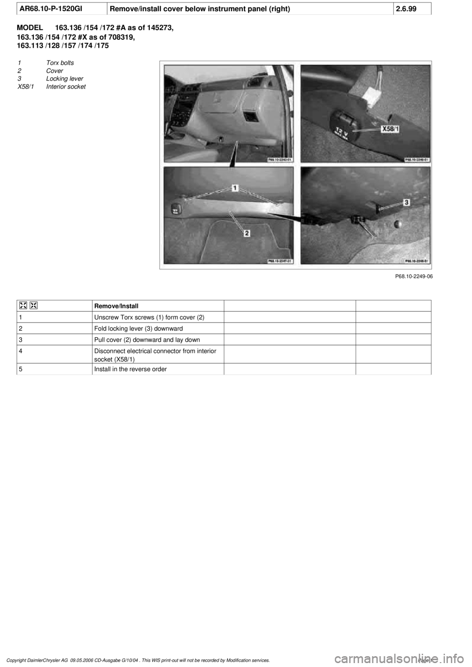
AR68.10-P-1520GI
Remove/install cover below instrument panel (right)
2.6.99
MODEL
163.136 /154 /172 #A as of 145273,
163.136 /154 /172 #X as of 708319,
163.113 /128 /157 /174 /175
P68.10-2249-06
1
Torx bolts
2
Cover
3
Locking lever
X58/1
I
nterior socket
Remove/Install
1
Unscrew Torx screws (1) form cover (2)
2
Fold locking lever (3) downward
3
Pull cover (2) downward and lay down
4
Disconnect electrical connector from interior
socket (X58/1)
5
Install in the reverse order
Copyright DaimlerChrysler AG 09.05.2006 CD-Ausgabe G/10/04 . This WIS print-out will not be recorde
d by Modification services.
Page 1
Page 3508 of 4133
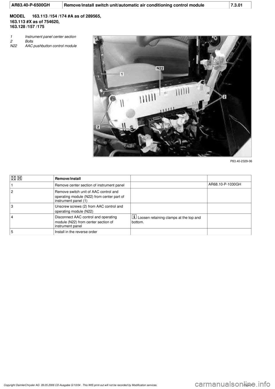
AR83.40-P-6500GH
Remove/install switch unit/automatic air conditioning control module
7.3.01
MODEL
163.113 /154 /174 #A as of 289565,
163.113 #X as of 754620,
163.128 /157 /175
P83.40-2329-06
1
Instrument panel center section
2
Bolts
N22
AAC pushbutton control module
Remove/install
1
Remove center section of instrument panel
AR68.10-P-1030GH
2
Remove switch unit of AAC control and
operating module (N22) from center part of
instrument panel (1)
3
Unscrew screws (2) from AAC control and
operating module (N22)
4
Disconnect AAC control and operating
module (N22) from center section of
instrument panel
Loosen retaining clamps at the top and
bottom.
5
Install in the reverse order
Copyright DaimlerChrysler AG 09.05.2006 CD-Ausgabe G/10/04 . This WIS print-out will not be recorde
d by Modification services.
Page 1
Page 3509 of 4133
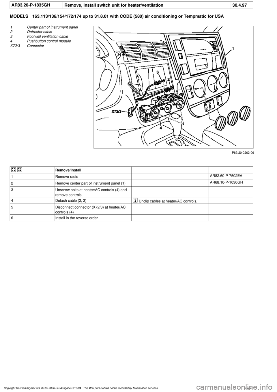
AR83.20-P-1835GH
Remove, install switch unit for heater/ventilation
30.4.97
MODELS
163.113/136/154/172/174 up to 31.8.01 with CODE (580) air conditioning or Tempmatic for USA
P83.20-0262-06
1
Center part of instrument panel
2
Defroster cable
3
Footwell ventilation cable
4
Pushbutton control module
X72/3
Connector
Remove/install
1
Remove radio
AR82.60-P-7502EA
2
Remove center part of instrument panel (1)
AR68.10-P-1030GH
3
Unscrew bolts at heater/AC controls (4) and
remove controls
4
Detach cable (2, 3)
Unclip cables at heater/AC controls.
5
Disconnect connector (X72/3) at heater/AC
controls (4)
6
Install in the reverse order
Copyright DaimlerChrysler AG 09.05.2006 CD-Ausgabe G/10/04 . This WIS print-out will not be recorde
d by Modification services.
Page 1
Page 3510 of 4133
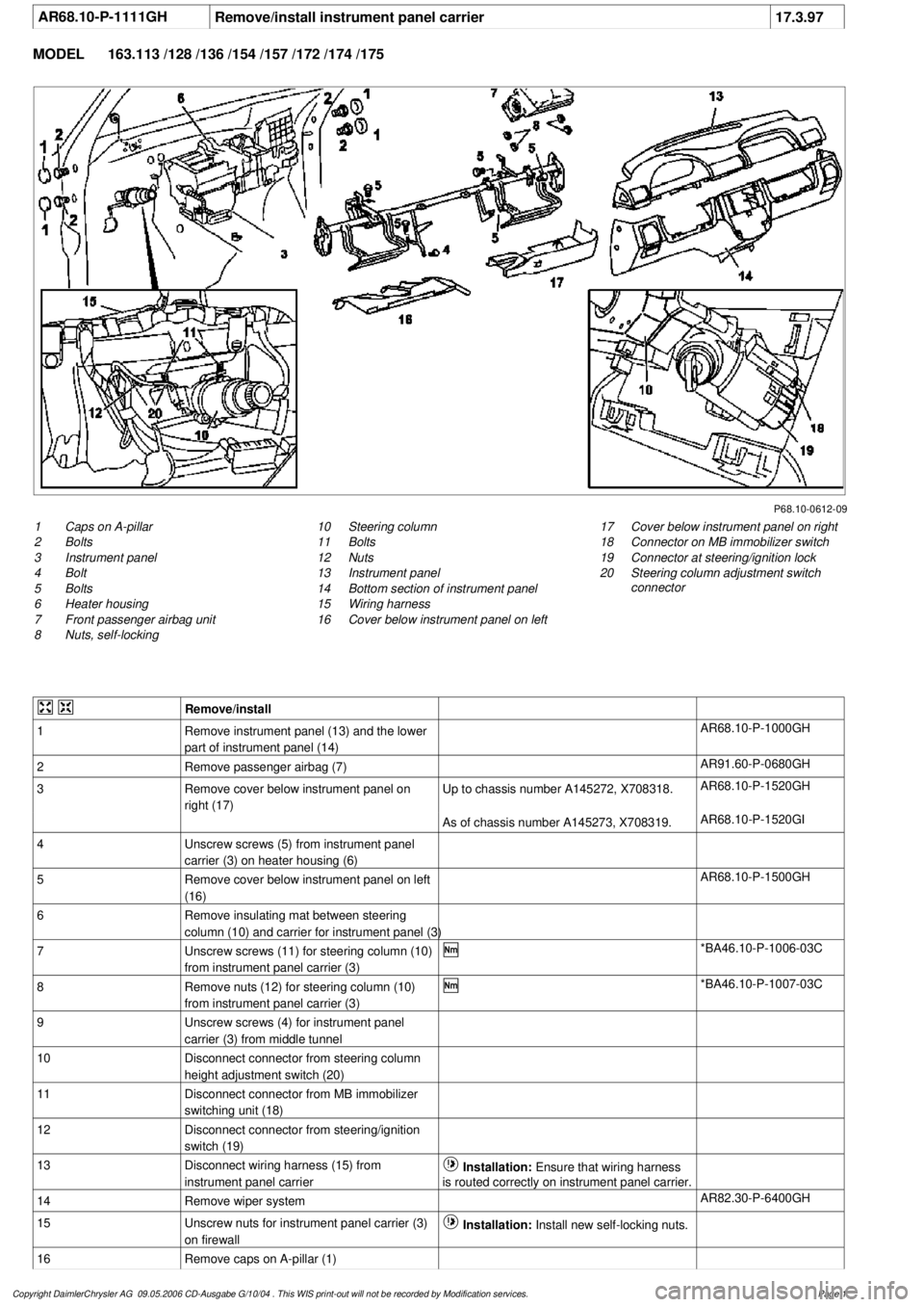
AR68.10-P-1111GH
Remove/install instrument panel carrier
17.3.97
MODEL
163.113 /128 /136 /154 /157 /172 /174 /175
P68.10-0612-09
1
Caps on A-pillar
2
Bolts
3
Instrument panel
4
Bolt
5
Bolts
6
Heater housing
7
Front passenger airbag unit
8
Nuts, self-locking
17
Cover below instrument panel on right
18
Connector on MB immobilizer switch
19
Connector at steering/ignition lock
20
Steering column adjustment switch
connector
10
Steering column
11
Bolts
12
Nuts
13
Instrument panel
14
Bottom section of instrument panel
15
Wiring harness
16
Cover below instrument panel on left
Remove/install
1
Remove instrument panel (13) and the lower
part of instrument panel (14)
AR68.10-P-1000GH
2
Remove passenger airbag (7)
AR91.60-P-0680GH
3
Remove cover below instrument panel on
right (17)
Up to chassis number A145272, X708318.
AR68.10-P-1520GH
As of chassis number A145273, X708319.
AR68.10-P-1520GI
4
Unscrew screws (5) from instrument panel
carrier (3) on heater housing (6)
5
Remove cover below instrument panel on left
(16)
AR68.10-P-1500GH
6
Remove insulating mat between steering
column (10) and carrier for instrument panel (3)
7
Unscrew screws (11) for steering column (10)
from instrument panel carrier (3)
*BA46.10-P-1006-03C
8
Remove nuts (12) for steering column (10)
from instrument panel carrier (3)
*BA46.10-P-1007-03C
9
Unscrew screws (4) for instrument panel
carrier (3) from middle tunnel
10
Disconnect connector from steering column
height adjustment switch (20)
11
Disconnect connector from MB immobilizer
switching unit (18)
12
Disconnect connector from steering/ignition
switch (19)
13
Disconnect wiring harness (15) from
instrument panel carrier
Installation:
Ensure that wiring harness
is routed correctly on instrument panel carrier.
14
Remove wiper system
AR82.30-P-6400GH
15
Unscrew nuts for instrument panel carrier (3)
on firewall
Installation:
Install new self-locking nuts.
16
Remove caps on A-pillar (1)
Copyright DaimlerChrysler AG 09.05.2006 CD-Ausgabe G/10/04 . This WIS print-out will not be recorde
d by Modification services.
Page 1