MERCEDES-BENZ ML430 1997 Complete Repair Manual
Manufacturer: MERCEDES-BENZ, Model Year: 1997, Model line: ML430, Model: MERCEDES-BENZ ML430 1997Pages: 4133, PDF Size: 88.89 MB
Page 3731 of 4133
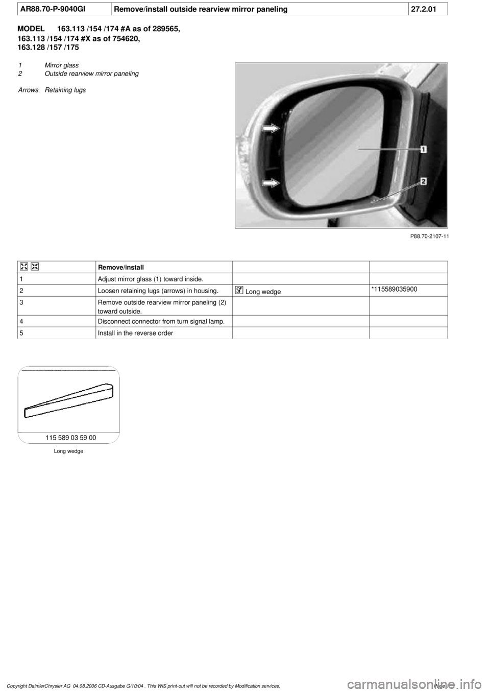
AR88.70-P-9040GI
Remove/install outside rearview mirror paneling
27.2.01
MODEL
163.113 /154 /174 #A as of 289565,
163.113 /154 /174 #X as of 754620,
163.128 /157 /175
P88.70-2107-11
1
Mirror glass
2
Outside rearview mirror paneling
Arrows Retaining lugs
Remove/install
1
Adjust mirror glass (1) toward inside.
2
Loosen retaining lugs (arrows) in housing.
Long wedge
*115589035900
3
Remove outside rearview mirror paneling (2)
toward outside.
4
Disconnect connector from turn signal lamp.
5
Install in the reverse order
Long wedge
115 589 03 59 00
Copyright DaimlerChrysler AG 04.08.2006 CD-Ausgabe G/10/04 . This WIS print-out will not be recorde
d by Modification services.
Page 1
Page 3732 of 4133
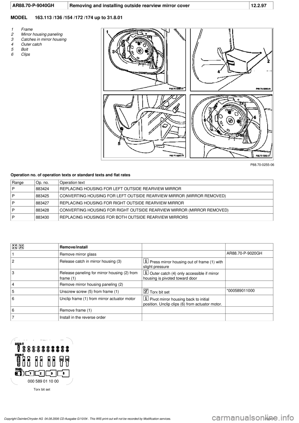
AR88.70-P-9040GH
Removing and installing outside rearview mirror cover
12.2.97
MODEL
163.113 /136 /154 /172 /174 up to 31.8.01
P88.70-0255-06
1
Frame
2
Mirror housing paneling
3
Catches in mirror housing
4
Outer catch
5
Bolt
6
Clips
Operation no. of operation texts or standard texts and flat rates
Range
Op. no.
Operation text
P
883424
REPLACING HOUSING FOR LEFT OUTSIDE REARVIEW MIRROR
P
883425
CONVERTING HOUSING FOR LEFT OUTSIDE REARVIEW MIRROR (MIRROR REMOVED)
P
883427
REPLACING HOUSING FOR RIGHT OUTSIDE REARVIEW MIRROR
P
883428
CONVERTING HOUSING FOR RIGHT OUTSIDE REARVIEW MIRROR (MIRROR REMOVED)
P
883430
REPLACING HOUSINGS FOR BOTH OUTSIDE REARVIEW MIRRORS
Remove/install
1
Remove mirror glass
AR88.70-P-9020GH
2
Release catch in mirror housing (3)
Press mirror housing out of frame (1) with
slight pressure
3
Release paneling for mirror housing (2) from
frame (1)
Outer catch (4) only accessible if mirror
housing is pivoted toward door
4
Remove mirror housing paneling (2)
5
Unscrew screw (5) from frame (1)
Torx bit set
*000589011000
6
Unclip frame (1) from mirror actuator motor
Pivot mirror housing back to initial
position. Unclip clips (6) from actuator motor.
6
Remove frame (1)
7
Install in the reverse order
Torx bit set
000 589 01 10 00
Copyright DaimlerChrysler AG 04.08.2006 CD-Ausgabe G/10/04 . This WIS print-out will not be recorde
d by Modification services.
Page 1
Page 3733 of 4133
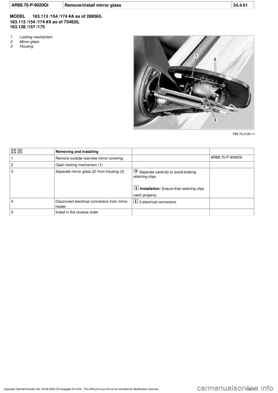
AR88.70-P-9020GI
Remove/install mirror glass
24.4.01
MODEL
163.113 /154 /174 #A as of 289565,
163.113 /154 /174 #X as of 754620,
163.128 /157 /175
P88.70-2126-11
1
Locking mechanism
2
Mirror glass
3
Housing
Removing and installing
1
Remove outside rearview mirror covering
AR88.70-P-9040GI
2
Open locking mechanism (1)
3
Separate mirror glass (2) from housing (3)
Separate carefully to avoid braking
retaining clips.
Installation:
Ensure that retaining clips
catch properly.
4
Disconnect electrical connectors from mirror
heater
3 electrical connectors.
5
Install in the reverse order
Copyright DaimlerChrysler AG 04.08.2006 CD-Ausgabe G/10/04 . This WIS print-out will not be recorde
d by Modification services.
Page 1
Page 3734 of 4133

GF54.30-P-4104A
Outside temperature display, location/function
8.7.99
MODEL
129
MODEL
140 as of 1.6.96
MODEL
170
MODEL
163, 202 with CODE (240a) Outside temperature display
MODEL
202 as of 1.8.96
MODEL
168
MODEL
208 up to 31.7.99,
210 as of 1.6.96 up to 30.6.99
To display the temperature, the
outside temperature indicator
A1p4
requires:
D
the outside temperature
D
the speed signal
D
the engine running time
and
D
the coolant temperature (model 129, and model 140 as of
1.6.96, model 170, model 202 as of 08/96 and model 163,
model 168, model 210)
The outside temperature is determined by the outside temperature
indicator temperature sensor B14. The temperature sensor is
installed at the front left of the vehicle under the bumper and
connected to the instrument cluster A1 via the 21 or 25-pin
connector, coding part A terminal 1 and 2.
The speed signal, engine running time and engine temperature are
determined internally by the instrument cluster A1.
Since the outside temperature display depends on the speed, engine
running time and coolant temperature, high temperatures (influenced
by the heat generated by the engine, for example) are not displayed
when the vehicle is stationary or moving slowly.
Function, model 202 until 08/95
When the ignition is switched on and off and at speeds below approx.
20 km/h, the last temperature measured is stored and displayed.
If the measured outside temperature drops below the stored value,
the current measured temperature is displayed.
If the outside temperature rises above the stored value, the current
measured outside temperature is displayed only after the following
delays:
D
When the engine is not running, the current outside
temperature is only displayed after 6 times the engine running
time. For example, if the preceding running time was 5 minutes,
the current temperature is not displayed until after 30 minutes.
The maximum delay, however, is 1 hour.
Up to 09.94
D
At vehicle speeds between 20-60 km/h, outside temperatures
are displayed after a delay of approx. 5 min.
D
At vehicle speeds over 60 km/h, outside temperatures are
displayed after a delay of approx. 2 minutes.
As of 09.94
D
At vehicle speeds between 20-45 km/h, outside temperatures
are displayed after a delay of approx. 3 min.
D
At vehicle speeds over 45 km/h, outside temperatures are
displayed after a delay of approx. 1.5 min.
Function
Model 129, model 140 as of 1.6.96, model 170, model 202 as of
08/96, model 163, model 168, model 208 and model 210
D
When the ignition is turned on or off
and with an engine temperature < 60°C
the current temperature is always stored and displayed.
D
When the ignition is turned off
and with an engine temperature < 60°C
the temperature last measured is stored and displayed.
D
When the ignition is turned on
and when an engine temperature < 60(C
The stored temperature is displayed.
If the measured outside temperature drops below the stored value,
the current measured temperature is displayed.
If the outside temperature rises above the stored value, the current
measured outside temperature is displayed only after the following
delays:
D
When the engine is not running, the current outside
temperature is only displayed after 6 times the engine running
time. For example, if the preceding running time was 5 minutes,
the current temperature is not displayed until after 30 minutes.
The maximum delay, however, is 1 hour.
D
At vehicle speeds between 20-45 km/h, outside temperatures
are displayed after a delay of approx. 3 minutes.
D
At vehicle speeds above 45 km/h, outside temperatures are
displayed after a delay of approx. 1.5 minutes.
Copyright DaimlerChrysler AG 05.06.2006 CD-Ausgabe G/10/04 . This WIS print-out will not be recorde
d by Modification services.
Page 1
Page 3735 of 4133
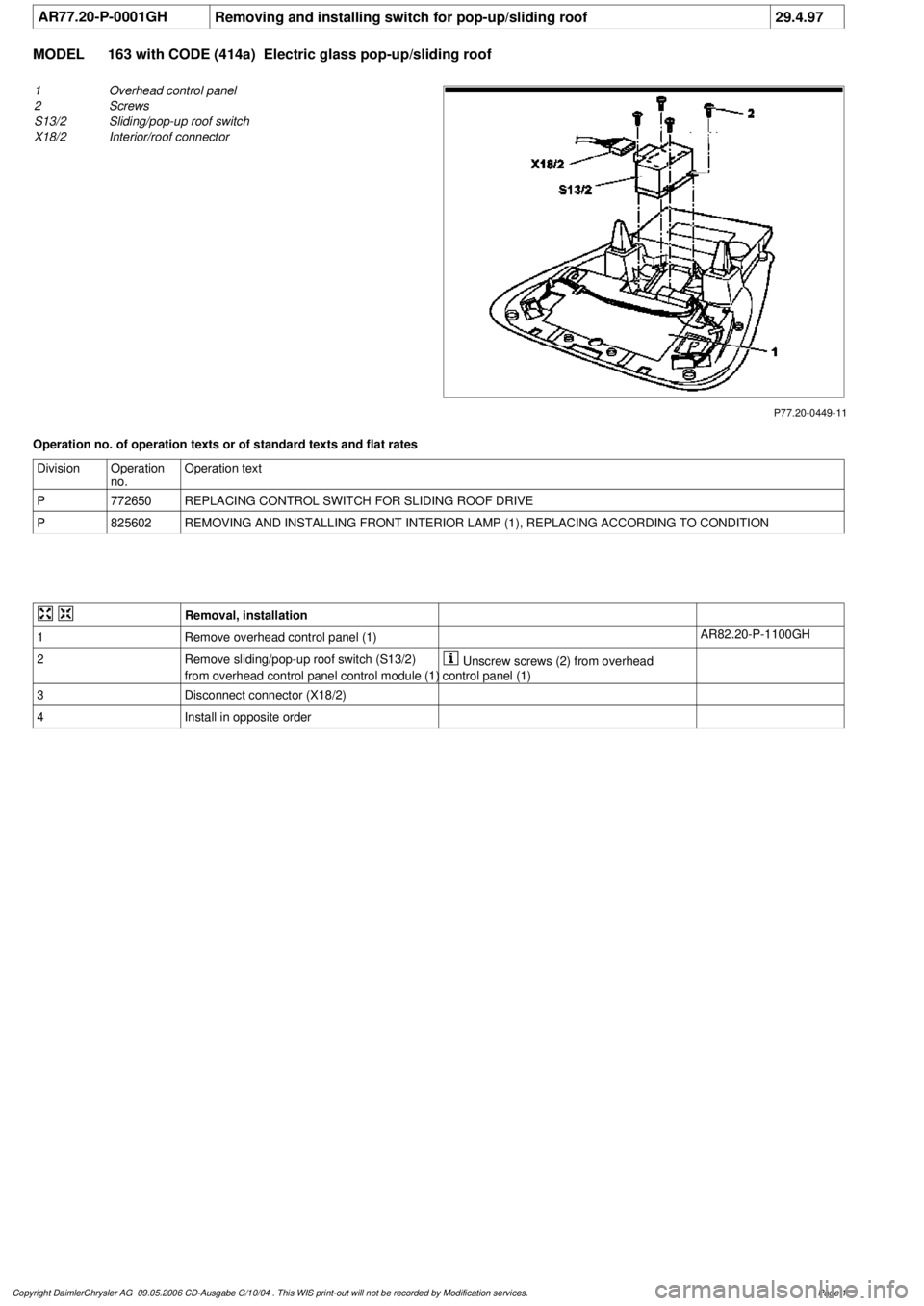
AR77.20-P-0001GH
Removing and installing switch for pop-up/sliding roof
29.4.97
MODEL
163 with CODE (414a) Electric glass pop-up/sliding roof
P77.20-0449-11
1
Overhead control panel
2
Screws
S13/2
Sliding/pop-up roof switch
X18/2
Interior/roof connector
Operation no. of operation texts or of standard texts and flat rates
Division
Operation
no.
Operation text
P
772650
REPLACING CONTROL SWITCH FOR SLIDING ROOF DRIVE
P
825602
REMOVING AND INSTALLING FRONT INTERIOR LAMP (1), REPLACING ACCORDING TO CONDITION
Removal, installation
1
Remove overhead control panel (1)
AR82.20-P-1100GH
2
Remove sliding/pop-up roof switch (S13/2)
from overhead control panel control module (1)
Unscrew screws (2) from overhead
control panel (1)
3
Disconnect connector (X18/2)
4
Install in opposite order
Copyright DaimlerChrysler AG 09.05.2006 CD-Ausgabe G/10/04 . This WIS print-out will not be recorde
d by Modification services.
Page 1
Page 3736 of 4133
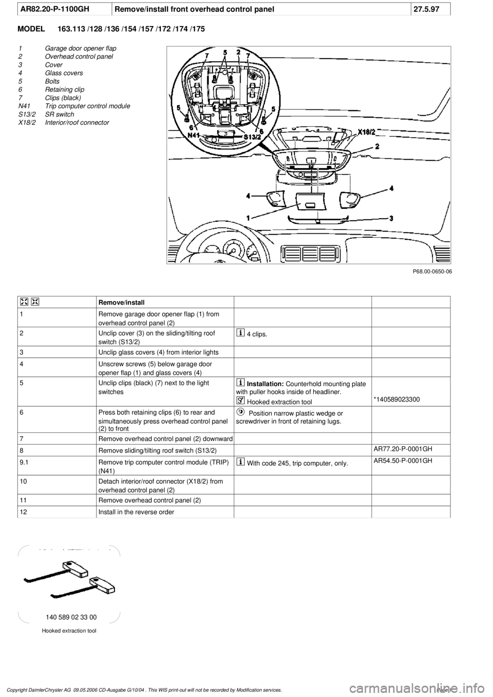
AR82.20-P-1100GH
Remove/install front overhead control panel
27.5.97
MODEL
163.113 /128 /136 /154 /157 /172 /174 /175
P68.00-0650-06
1
Garage door opener flap
2
Overhead control panel
3
Cover
4
Glass covers
5
Bolts
6
Retaining clip
7
Clips (black)
N41
Trip computer control module
S13/2
SR switch
X18/2
Interior/roof connector
Remove/install
1
Remove garage door opener flap (1) from
overhead control panel (2)
2
Unclip cover (3) on the sliding/tilting roof
switch (S13/2)
4 clips.
3
Unclip glass covers (4) from interior lights
4
Unscrew screws (5) below garage door
opener flap (1) and glass covers (4)
5
Unclip clips (black) (7) next to the light
switches
Installation:
Counterhold mounting plate
with puller hooks inside of headliner.
Hooked extraction tool
*140589023300
6
Press both retaining clips (6) to rear and
simultaneously press overhead control panel
(2) to front
Position narrow plastic wedge or
screwdriver in front of retaining lugs.
7
Remove overhead control panel (2) downward
8
Remove sliding/tilting roof switch (S13/2)
AR77.20-P-0001GH
9.1
Remove trip computer control module (TRIP)
(N41)
With code 245, trip computer, only.
AR54.50-P-0001GH
10
Detach interior/roof connector (X18/2) from
overhead control panel (2)
11
Remove overhead control panel (2)
12
Install in the reverse order
Hooked extraction tool
140 589 02 33 00
Copyright DaimlerChrysler AG 09.05.2006 CD-Ausgabe G/10/04 . This WIS print-out will not be recorde
d by Modification services.
Page 1
Page 3737 of 4133
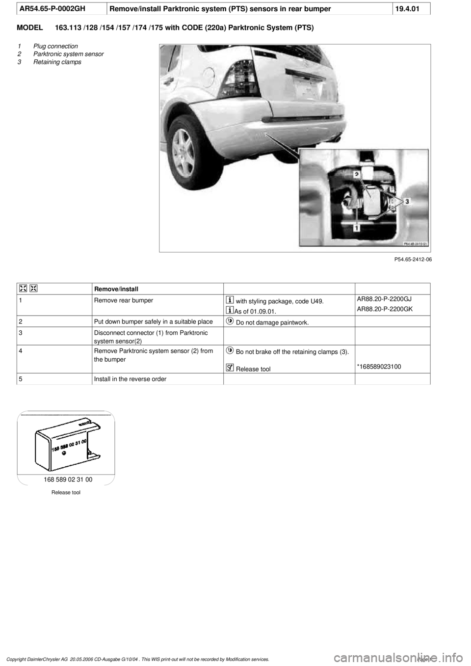
AR54.65-P-0002GH
Remove/install Parktronic system (PTS) sensors in rear bumper
19.4.01
MODEL
163.113 /128 /154 /157 /174 /175 with CODE (220a) Parktronic System (PTS)
P54.65-2412-06
1
Plug connection
2
Parktronic system sensor
3
Retaining clamps
Remove/install
1
Remove rear bumper
with styling package, code U49.
AR88.20-P-2200GJ
As of 01.09.01.
AR88.20-P-2200GK
2
Put down bumper safely in a suitable place
Do not damage paintwork.
3
Disconnect connector (1) from Parktronic
system sensor(2)
4
Remove Parktronic system sensor (2) from
the bumper
Bo not brake off the retaining clamps (3).
Release tool
*168589023100
5
Install in the reverse order
Release tool
168 589 02 31 00
Copyright DaimlerChrysler AG 20.05.2006 CD-Ausgabe G/10/04 . This WIS print-out will not be recorde
d by Modification services.
Page 1
Page 3738 of 4133
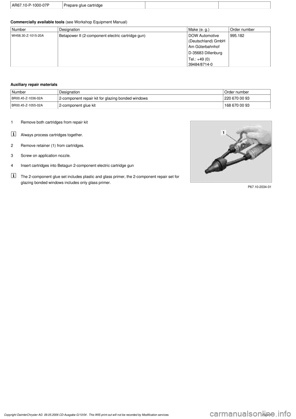
AR67.10-P-1000-07P
Prepare glue cartridge
Commercially available tools
(see Workshop Equipment Manual)
Number
Designation
Make (e. g.)
Order number
WH58.30-Z-1015-20A
Betapower II (2-component electric cartridge gun)
DOW Automotive
(Deutschland) GmbH
Am Güterbahnhof
D-35683 Dillenburg
Tel.: +49 (0)
39484/8714-0
995.182
Auxiliary repair materials
Number
Designation
Order number
BR00.45-Z-1036-02A
2-component repair kit for glazing bonded windows
220 670 00 93
BR00.45-Z-1055-02A
2-component glue kit
168 670 00 93
P67.10-2034-01
1
Remove both cartridges from repair kit
Always process cartridges together.
2
Remove retainer (1) from cartridges.
3
Screw on application nozzle.
4
Insert cartridges into Betagun 2-component electric cartridge gun
The 2-component glue set includes plastic and glass primer, the 2-component repair set for
glazing bonded windows includes only glass primer.
Copyright DaimlerChrysler AG 09.05.2006 CD-Ausgabe G/10/04 . This WIS print-out will not be recorde
d by Modification services.
Page 1
Page 3739 of 4133
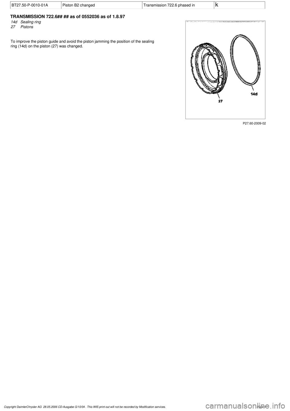
BT27.50-P-0010-01A
Piston B2 changed
Transmission 722.6 phased in
k
TRANSMISSION
722.6## ## as of 0552036 as of 1.8.97
P27.60-2009-02
14d
Sealing ring
27
Pistons
To improve the piston guide and avoid the piston jamming the position of the sealing
ring (14d) on the piston (27) was changed.
Copyright DaimlerChrysler AG 28.05.2006 CD-Ausgabe G/10/04 . This WIS print-out will not be recorde
d by Modification services.
Page 1
Page 3740 of 4133
AR03.10-P-7311-01V
Measure end clearance of piston rings
Modification notes
12.6.02
Value in line 1001 for Engine 113.967 modified from
0.012...0.060 to 0.033...0.07 and from 0010...0.030 to
0.01...0.04
Value in BE03.10-P-1001-05B for Engine
113.967 modified
*BE03.10-P-1001-05B
Test values for piston rings
Number
Designation
Engine 112.910/
911/912
Engine 112.920/
921/922/923/940/
941/942/943/944/
945/946/947/948/
960,
113.940/941/942/
943
Engine 113.944/
980/981/982/984
BE03.10-P-1001-05B
Vertical clearance of
piston ring
Groove 1
mm
0,012...0,0600,012...0,0600,012...0,060
Groove 2
mm
0,010...0,0300,010...0,0300,010...0,030
Test values for piston rings
Number
Designation
Engine 113.960/
961/962/963/965/
968
Engine
113.967
BE03.10-P-1001-05B
Vertical clearance of
piston ring
Groove 1
mm
0,012...0,0600,033...0,070
Groove 2
mm
0,010...0,030
0,01...0,04
Commercially available tools
(see Workshop Equipment Manual)
Number
Designation
Make (e.g.)
Order number
WH58.30-Z-1008-12A
Feeler gage
Stiefelmayer
D-73734 Esslingen
59
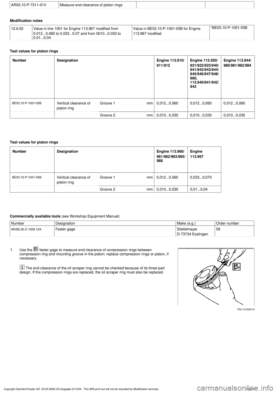
P03.10-2034-01
1
Use the
feeler gage to measure end clearance of compression rings between
compression ring and mounting groove in the piston; replace compression rings or piston, if
necessary.
The end clearance of the oil scraper ring cannot be checked because of its three-part
design. If the compression rings are replaced, the oil scraper ring must also be replaced.
Copyright DaimlerChrysler AG 20.05.2006 CD-Ausgabe G/10/04 . This WIS print-out will not be recorde
d by Modification services.
Page 1