MERCEDES-BENZ ML430 1997 Complete Repair Manual
Manufacturer: MERCEDES-BENZ, Model Year: 1997, Model line: ML430, Model: MERCEDES-BENZ ML430 1997Pages: 4133, PDF Size: 88.89 MB
Page 371 of 4133
1. Before proceeding, See AIR BAG SAFETY PRECAUTIONS . Disable air bag system. See
DISABLING & ACTIVATI NG AIR BAG SYSTEM
. Remove ignition key. Remove radio. Push up
and pull out heater control panel. Unplug 2 connectors. Remove scre w in middle of storage tray.
2. Bend up at top corners and lift out storage tray. Rem ove screws below storage tray. Lift wood trim panel
at rear, pull down and out of catches. Unplug swit ch connectors and remove wood trim panel. Unplug
connectors at control module and remove Torx mounting screws. Remove control module.
3. To install, reverse removal proce dure. Ensure SRS control module arro w points to front of vehicle. Set
parameters and program new SRS control module wi th Hand-Held Tester (965 589 00 01 00). Activate
air bag system. Perform system operation check to ensure system is functioning properly. See SYSTEM
OPERATION CHECK .
Removal & Installation (CLK & SLK)
1. Before proceeding, See AIR BAG SAFETY PRECAUTIONS . Disable air bag system. See
DISABLING & ACTIVATI NG AIR BAG SYSTEM
. Remove ignition key. Remove cover on center
console. Remove cover on shift lever. Remove ash tray housing with storage compartment at front of
center console. Unplug connectors at control module and remove Torx mounting screws. Remove control
module.
2. To install, reverse removal proce dure. Ensure SRS control module arro w points to front of vehicle. Set
parameters and program new SRS control module wi th Hand-Held Tester (965 589 00 01 00). Activate
air bag system. Perform system operation check to ensure system is functioning properly. See SYSTEM
OPERATION CHECK .
DRIVER-SIDE AIR BAG MODULE
Removal & Installation
1. Before proceeding, See AIR BAG SAFETY PRECAUTIONS . Disable air bag system. See
DISABLING & ACTIVATI NG AIR BAG SYSTEM
. Remove ignition key. Remove 2 Torx screws
from rear of steering wheel. Lift off air bag m odule enough to unplug connector from rear of module.
Place module away from work area, with pad facing upward.
2. To install, reverse removal procedure. Tighten Torx screws to specification. See TORQUE
SPECIFICATIONS . Activate air bag system. Perform system operation ch eck to ensure system is
functioning properly. See SYSTEM OPERATION CHECK
.
SIDE AIR BAG UNIT (DRIVER-SIDE & PASSENGER-SIDE)
Removal & Installation
1. Before proceeding, See AIR BAG SAFETY PRECAUTIONS . Disable air bag system. See
DISABLING & ACTIVATI NG AIR BAG SYSTEM
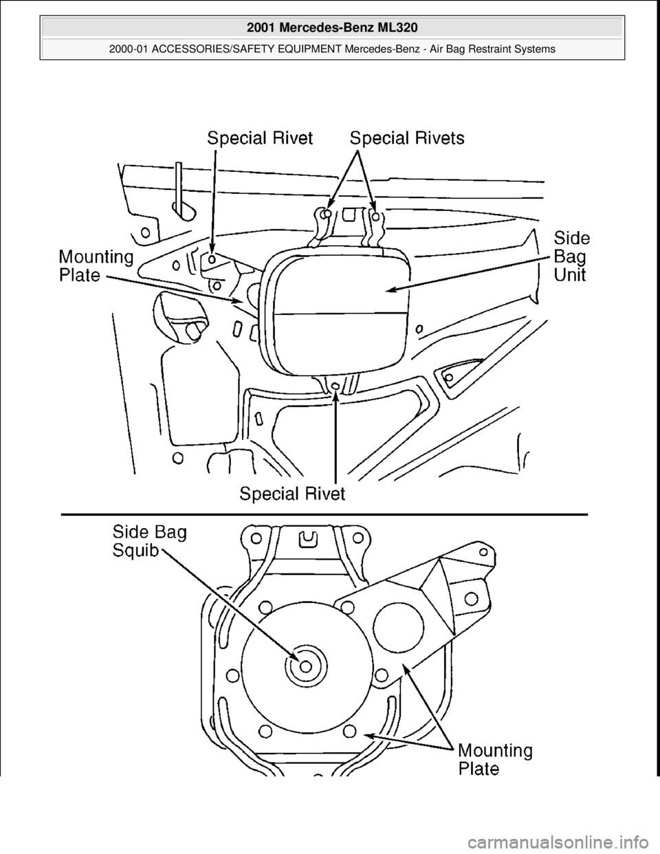
. Remove ignition key. Drill out rivets at
retaining plate of side air bag unit. Pull air bag unit out of door. Disconnect connector at driver-side air
bag squib. Remove unit from vehicle. See Fig. 2.
NOTE: Air bag module and steer
ing wheel must be replaced following a collision in
which air bag was deployed.
2001 Mercedes-Benz ML320
2000-01 ACCESSORIES/SAFETY EQUIPMENT Merc edes-Benz - Air Bag Restraint Systems
me
Saturday, October 02, 2010 3:44:45 PMPage 7 © 2006 Mitchell Repair Information Company, LLC.
Page 372 of 4133

2. To install, connect connector so that connector a udibly clicks when connector engages. Install unit in
door trim panel and rivet using only special rivets (Part No. 003 990 0097). Perform system operation
check to ensure s
ystem is functioning properly. See SYSTEM OPERATION CHECK .
2001 Mercedes-Benz ML320
2000-01 ACCESSORIES/SAFETY EQUIPMENT Merc edes-Benz - Air Bag Restraint Systems
me
Saturday, October 02, 2010 3:44:45 PMPage 8 © 2006 Mitchell Repair Information Company, LLC.
Page 373 of 4133
2001 Mercedes-Benz ML320
2000-01 ACCESSORIES/SAFETY EQUIPMENT Merc edes-Benz - Air Bag Restraint Systems
me
Saturday, October 02, 2010 3:44:45 PMPage 9 © 2006 Mitchell Repair Information Company, LLC.
Page 374 of 4133

Fig. 2: Removing Side Air Bag Unit (2000 Models)
Courtesy of MERCEDES-BENZ OF NORTH AMERICA.
SIDE AIR BAG SENSOR (DRIVER-SIDE & PASSENGER-SIDE)
Removal & Installation
1. Before proceeding, See AIR BAG SAFETY PRECAUTIONS . Disable air bag system. See
DISABLING & ACTIVATI NG AIR BAG SYSTEM
. Remove ignition key. On SLK 230, remove
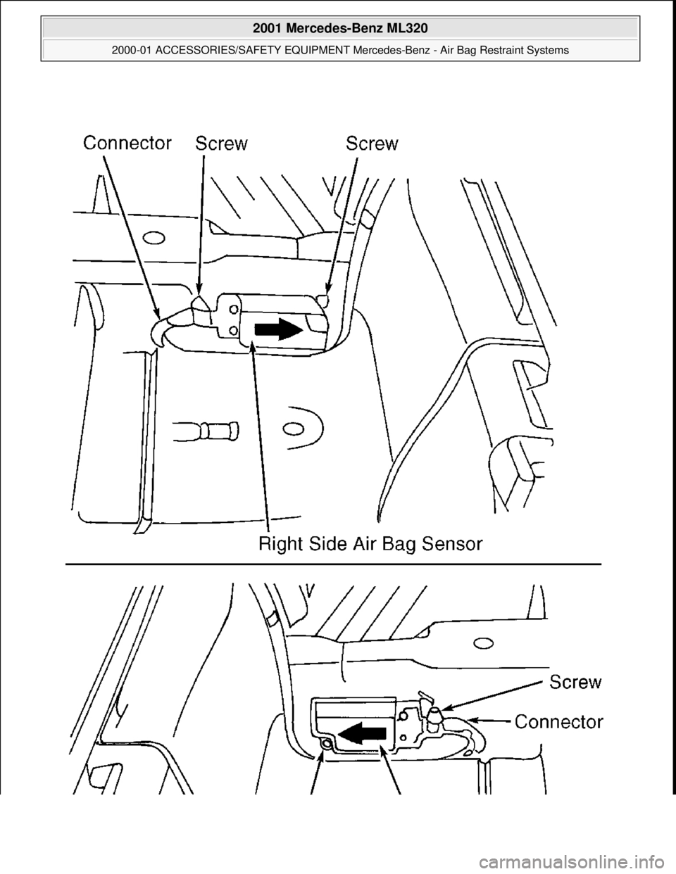
door sill moulding. On all models, re move front seat. Fold floor covering in area toward rear. Unclip
connector on side bag sensor. Remove 2 mounting screws. Rem ove sensor from vehicle.
2. To install, reverse removal proce dure. Ensure that arrow on sensor poi nts toward outside. Perform system
operation check to ensure system is functioning properly. See SYSTEM OPERATION CHECK
.
2001 Mercedes-Benz ML320
2000-01 ACCESSORIES/SAFETY EQUIPMENT Merc edes-Benz - Air Bag Restraint Systems
me
Saturday, October 02, 2010 3:44:45 PMPage 10 © 2006 Mitchell Repair Information Company, LLC.
Page 375 of 4133
2001 Mercedes-Benz ML320
2000-01 ACCESSORIES/SAFETY EQUIPMENT Merc edes-Benz - Air Bag Restraint Systems
me
Saturday, October 02, 2010 3:44:45 PMPage 11 © 2006 Mitchell Repair Information Company, LLC.
Page 376 of 4133
Fig. 3: Removing Side Air Bag Sensor (2000 E Class Shown; Others Are Similar)
Courtesy of MERCEDES-BENZ OF NORTH AMERICA.
OCCUPIED SEAT RECOGNITION SENSOR
Removal & Installation
1. Before proceeding, See AIR BAG SAFETY PRECAUTIONS . Disable air bag system. See
DISABLING & ACTIVATI NG AIR BAG SYSTEM
.
2. Remove cover on front seat cushion. Remove i gnition key. Unclip connection for occupied seat
recognition sensor on seat connector block. Remove electrical connection lead from seat and pull upward
out of rubberized fiber matting. See Fig. 4
.
3. To install, lay out occupied seat recognition sens or uniformly on rubberized fiber matting. Fabric side
should point upward. Do not kink occupied seat sens or. Reverse removal procedure. Perform system
operation check to ensure s
ystem is functioning properly. See SYSTEM OPERATION CHECK.
2001 Mercedes-Benz ML320
2000-01 ACCESSORIES/SAFETY EQUIPMENT Merc edes-Benz - Air Bag Restraint Systems
me
Saturday, October 02, 2010 3:44:45 PMPage 12 © 2006 Mitchell Repair Information Company, LLC.
Page 377 of 4133
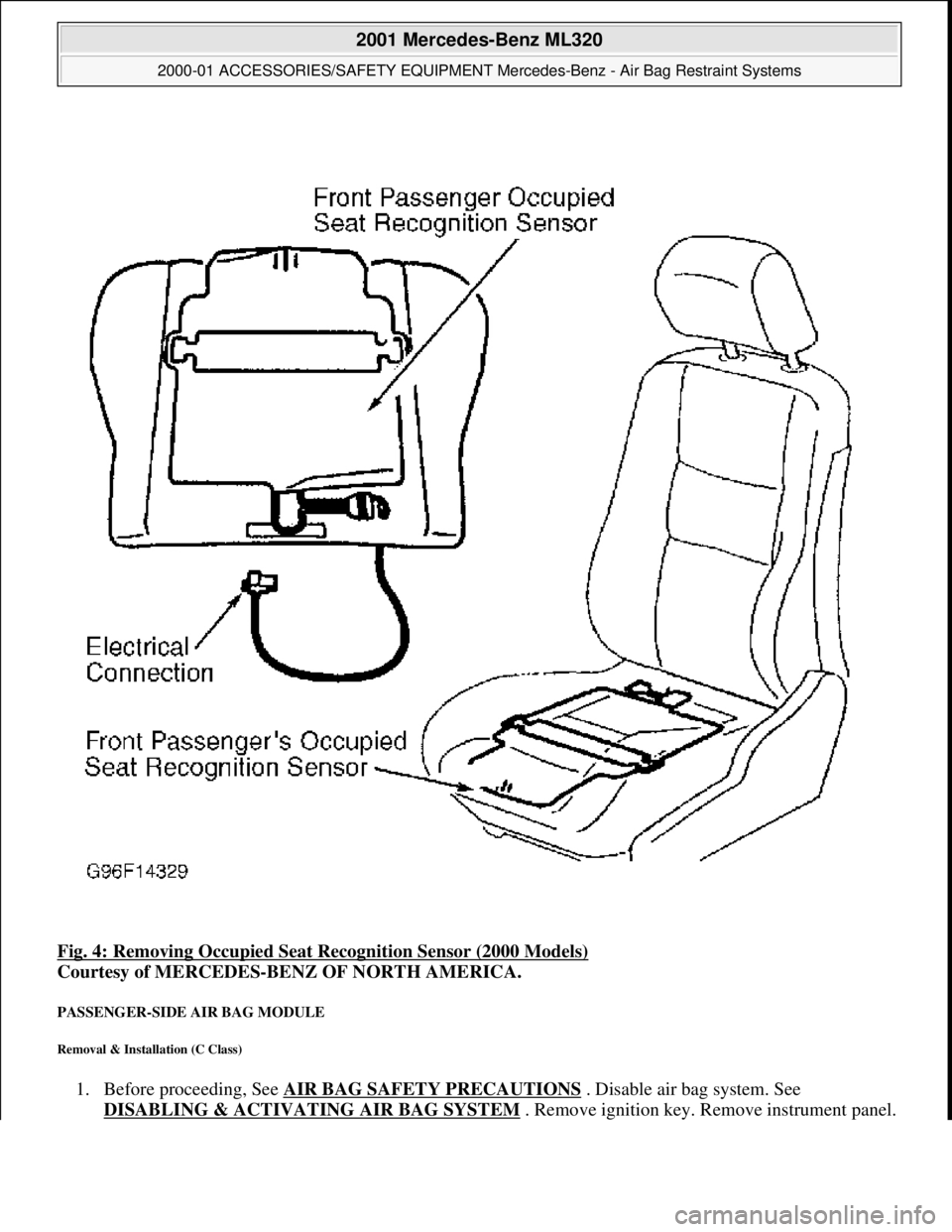
Fig. 4: Removing Occupied Seat Recognition Sensor (2000 Models)
Courtesy of MERCEDES-BENZ OF NORTH AMERICA.
PASSENGER-SIDE AIR BAG MODULE
Removal & Installation (C Class)
1. Before proceeding, See AIR BAG SAFETY PRECAUTIONS . Disable air bag system. See
DISABLING & ACTIVATI NG AIR BAG SYSTEM
. Remove ignition key. Remove instrument panel.
2001 Mercedes-Benz ML320
2000-01 ACCESSORIES/SAFETY EQUIPMENT Merc edes-Benz - Air Bag Restraint Systems
me
Saturday, October 02, 2010 3:44:45 PMPage 13 © 2006 Mitchell Repair Information Company, LLC.
Page 378 of 4133
Disconnect passenger-side air bag module squib connector. Remove 4 passenger-side air bag module
mounting nuts.
2. To install, reverse removal proc edure. Ensure passenger-side air bag module squib connector audibly
clicks when connecting connector. Activate air bag system. Perform system operation check to ensure
system is functioning properly. See SYSTEM OPERATION CHECK
.
Removal & Installation (E Class)
1. Before proceeding, See AIR BAG SAFETY PRECAUTIONS . Disable air bag system. See
DISABLING & ACTIVATI NG AIR BAG SYSTEM
. Remove ignition key. Remove 2 central
mounting bolts for passenger-side air bag module. Li ft air bag module enough to unplug connector from
rear of module. Place module away fr om work area, with pad facing upward.
2. If necessary to replace passenger air bag instal lation frame, remove 4 frame mounting bolts. Remove
installation frame from vehicle.
3. To install air bag module or inst allation frame, reverse removal proc edure. Activate air bag system.
Perform system operation check to ensu re system is functioning properly. See SYSTEM OPERATION
CHECK .
Removal & Installation (S Class)
1. Before proceeding, See AIR BAG SAFETY PRECAUTIONS . Disable air bag system. See
DISABLING & ACTIVATI NG AIR BAG SYSTEM
. Remove ignition key. Open glove box door.
Remove 4 clips securing glove bo x. Remove glove box compartment. When removing compartment,
disconnect glove box light. Remove glove box door lock striker.
2. Disconnect passenger-side air bag module squib c onnector. Remove 4 passenger-side air bag module
mounting nuts. Remove passenger- side air bag module through glove box opening. Place module away
from work area with pad facing up.
3. To install, reverse removal proc edure. Ensure module squib connector audibly clicks when connecting
connector. Activate air bag system. Perform system operation check to ensure system is functioning
properly. See SYSTEM OPERATION CHECK
.
Removal & Installation (SL Class)
1. Before proceeding, See AIR BAG SAFETY PRECAUTIONS . Disable air bag system. See
DISABLING & ACTIVATI NG AIR BAG SYSTEM
. Remove ignition key. Remove cover below
instrument panel. Remove one bolt in installation slot of center air outlet, and one bolt below right air
outlet.
2. Remove air bag panel (3 Phillips screws and 2 hex bol ts). Unplug connector at squib of passenger-side air
bag unit. Remove mounting bo lts. Pull off and take air bag out of panel opening.
3. To install air bag module, reverse removal procedur e. Activate air bag system. Perform system operation
check to ensure system is functioning properly. See SYSTEM OPERATION CHECK
.
Removal & Installation (CLK 320)
1. Before proceeding, See AIR BAG SAFETY PRECAUTIONS . Disable air bag system. See
DISABLING & ACTIVATI NG AIR BAG SYSTEM
. Remove ignition key. Remove instrument panel.
Disconnect passen
ger-side air bag module connector. Remove 4 screws and passenger-side air bag
2001 Mercedes-Benz ML320
2000-01 ACCESSORIES/SAFETY EQUIPMENT Merc edes-Benz - Air Bag Restraint Systems
me
Saturday, October 02, 2010 3:44:45 PMPage 14 © 2006 Mitchell Repair Information Company, LLC.
Page 379 of 4133
module.
2. To install air bag module, reverse removal procedur e. Activate air bag system. Perform system operation
check to ensure system is functioning properly. See SYSTEM OPERATION CHECK
.
Removal & Installation (SLK 320)
1. Before proceeding, See AIR BAG SAFETY PRECAUTIONS . Disable air bag system. See
DISABLING & ACTIVATI NG AIR BAG SYSTEM
. Remove ignition key. Remove top section of
instrument panel. Fold vapor barrier toward front to reveal 2 screws. Disconnect passenger-side air bag
module connector. Remove 4 screws and passenger-side air bag module.
2. To install air bag module, reverse removal procedur e. Activate air bag system. Perform system operation
check to ensure system is functioning properly. See SYSTEM OPERATION CHECK
.
DIAGNOSTICS
Before proceeding, see AIR BAG SAFETY PRECAUTIONS
. The SRS control module is capable of
diagnosing air bag system components and ETR components. If a fault is detected by the SRS control module
or system is malfunctioning, SRS warning light will do one or more of the following:
SRS warning light goes out after 2 minutes. System fault is noted, however occupant protection is not
affected. See RETRIEVING FAULT CODES
.
SRS warning light illuminates cont inuously. System is faulty which may result in a non deployment or
false deployment. See RETRIEVING FAULT CODES
.
SRS warning light blinks continuous ly. Control module has been replaced without setting control module
parameters.
RETRIEVING FAULT CODES
1. Check vehicle fuses. Replace any blown fuses as nece ssary. Ensure vehicle battery voltage is 11 volts or
more. Ensure SRS warning light functions. Turn i gnition off. Connect Hand-Held Tester (HHT) (965 589
00 01) to Data Link Connector (DLC).
2. DLC is located in right rear corner of engine comp artment. It may be necessary to use Adapter (965 589
00 40 or 965 589 00 50) to connect HHT to DLC. Afte r HHT displays module number and version, press
return key to start diagnosis. Us ing HHT, follow HHT prompts to re trieve SRS fault codes. For SRS
control modules beginning with number 000, fault c ode 1 is valid. For SRS control modules beginning
with number 001, fault code 2 is valid. See Fig. 6
.
3. HHT will display a 3 digit fault code, and may display additional graphic information. This additional
graphic information will help in diagnosis of fault code. See Fig. 5
. During diagnosis HHT will display 4
different graphic displays info rming technician if a test passes or fail s, or if seat belt buckle is latched or
NOTE: After component replacement, perf
orm a system operation check to ensure
proper system operation. S ee SYSTEM OPERATION CHECK
.
NOTE: Fault codes may only be retrieved us ing Hand-Held Tester (965 589 00 01) and
Adapter (965 589 00 40 or 965 589 00 50).
2001 Mercedes-Benz ML320
2000-01 ACCESSORIES/SAFETY EQUIPMENT Merc edes-Benz - Air Bag Restraint Systems
me
Saturday, October 02, 2010 3:44:45 PMPage 15 © 2006 Mitchell Repair Information Company, LLC.
Page 380 of 4133
not latched. See Fig. 5 .
4. These graphic displays are disp layed as applicable by HHT during testing. See FAULT CODES table.
During diagnosis, system values are continuously updated, so by moving components and connections
intermittent failures can be diagnosed. HHT will also display fault frequency and time span.
5. After retrieving fault codes using HHT, carefully observe testing instructions in this article. Some testing
is executed with HHT connected to DLC and some tests are executed with HHT removed from DLC.
Turn ignition off when removing or connecting HHT to DLC.
6. Contact Box (124 589 00 21) with Test Cable (124 589 35 63) is necessary to complete some test steps.
Resistance Substitution Unit (124 589 09 63) is necessa ry to substitute resistance values for testing
purposes.
2001 Mercedes-Benz ML320
2000-01 ACCESSORIES/SAFETY EQUIPMENT Merc edes-Benz - Air Bag Restraint Systems
me
Saturday, October 02, 2010 3:44:45 PMPage 16 © 2006 Mitchell Repair Information Company, LLC.