trip computer MERCEDES-BENZ ML500 1997 Complete Owner's Guide
[x] Cancel search | Manufacturer: MERCEDES-BENZ, Model Year: 1997, Model line: ML500, Model: MERCEDES-BENZ ML500 1997Pages: 4133, PDF Size: 88.89 MB
Page 1141 of 4133

337 Index
Sun visor 132
Supplemental Restraint System
(SRS) 314
Switching off
Automatic climate control 137
ESP 81
Hazard warning flasher 112
Headlamps 54
Rapid seat heating 99
Transmission control – LOW RANGE
mode 125
Switching on
Automatic climate control 137
ESP 82
Front fog lamps 111
Front fog lamps, rear fog lamp 111
Hazard warning flasher 112
Headlamps 48
High beams 110
Rapid seat heating* 98
Seat heating* 98
Transmission control – LOW RANGE
mode 125
Trip computer* 186
Windshield wipers 49Synchronizing
ESP 246
Power windows 146
Remote control 263
Sliding/pop-up roof* 149
T
Tachometer 26, 118
Displaying gear range 121
Tail lamps 270
Cleaning 236
Replacing bulbs 267Tar stains 235
Technical data 302
Brake fluid 302
Coolants 304
Electrical system 297
Engine 294
Engine oil 302
Engine oil additives 302
Fuel requirements 303
Gasoline additives 303
Main dimensions 298
Premium unleaded gasoline 303
Rims and tires 295
Weights 299
Windshield and headlamp washer
system 307
Tele Aid System* 315
Page 1143 of 4133

339 Index
Traction 308, 315
Trailer
Attaching 208
Loading 208
Towing 209
Trailer hitches 207
Trailer towing 206
Attaching a trailer 208
Checking weights 208
Electrical connections 207
Hitches 207
Loading 208
Weights and ratings 207
Trailer weights and ratings 207
Transfer case 315
Transmission control – LOW RANGE
mode 125
Switching off 125
Switching on 125
Transmission selector lever 264
Unlocking manually 264
Tread depth (tires) 230
Treadwear 308Trip computer* 29, 186
Average fuel consumption 189
Compass 187
Country 190
Distance remaining 189
Language 190
Selecting functions 186
Setting date 186
Stop watch 189
Switching on 186
Trip odometer
Resetting 118
Trip odometer display 117
Trunk see Cargo compartment 89
Turn signal lamps
Replacing bulbs 266, 267, 269
Turn signals 49
Additional in mirrors 266
Cleaning lenses 236
Front bulbs 266
Indicator lamps 25
Rear bulbs 267, 270
Turning off
Engine 54U
Unlocking 32, 88
Centrally from inside 94
Driver’s door in an emergency 261
Driver’s door, fuel filler flap 89
Fuel filler flap 214
In an emergency 261
Transmission selector lever
manually 264
Vehicle in an emergency 179
With the remote control 32
Upgrade signals
Tele Aid* 178
Uphill driving
Cruise control 151
Upholstery
Cleaning 239
Upshifting 120
Page 1144 of 4133

340 IndexUseful features 164
Ashtrays and cigarette lighter 168
Cup holder 166
Electrical outlet 170
Garage door opener 180
Interior storage spaces 164
Programming or reprogramming the in-
tegrated remote control 182
Tele Aid* 171
Telephone* 170
Trip computer* 186
V
Vehicle
Locking 28
Locking in an emergency 262
Lowering 276
Proper use of 17
Service battery 278
Towing 283
Unlocking 28
Unlocking in an emergency 261
Vehicle and trailer weights and
ratings 207
Vehicle battery 278Vehicle care
Cup holder 238
Engine cleaning 236
Gear selector lever 238
Hard plastic trim items 238
Headlamps 236
Instrument cluster 238
Leather upholstery 239
Light alloy wheels 238
MB Tex upholstery 239
Ornamental moldings 236
Paintwork 235
Parktronic* system sensor 237
Plastic and rubber parts 239
Power washer 235
Seat belts 238
Steering wheel 238
Tail lamps 236
Tar stains 235
Turn signals 236
Upholstery 239
Vehicle washing 236
Window cleaning 237
Wiper blades 237Vehicle identification number (VIN) 292
Vehicle jack 258
Vehicle lighting
Checking 216
Vehicle tool kit 257
Vehicle with CD-changer* 258
Vehicle washing 236
VIN (Vehicle Identification Number) 292,
315
Voice control system* 315
W
Warning indicators
Parktronic* 155
Warning sounds
Drivers seat belts 64
Parking brake 48
Warranty coverage 291
Washer fluid see Windshield washer fluid
Washing the vehicle 234
Page 1770 of 4133
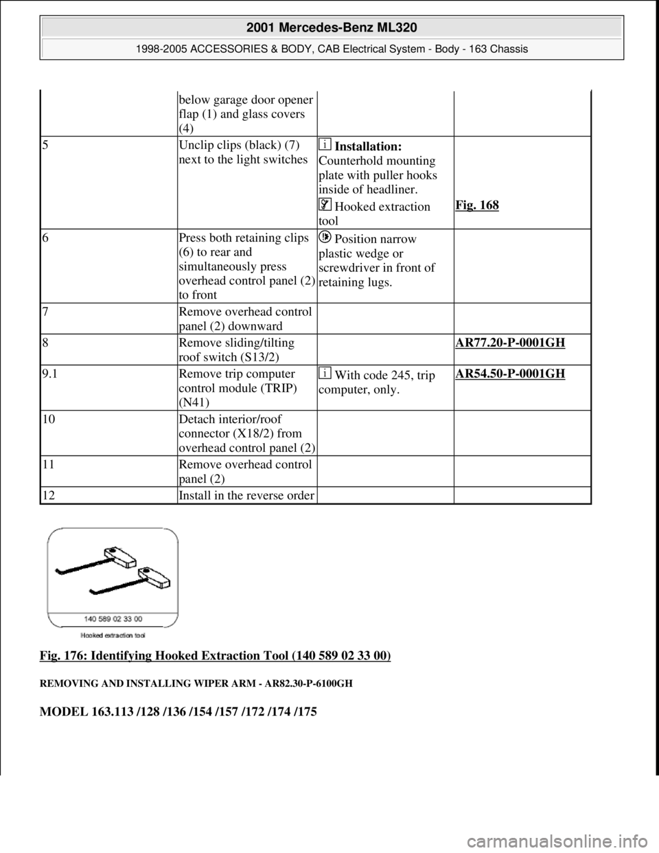
Fig. 176: Identifying Hooked Extraction Tool (140 589 02 33 00)
REMOVING AND INSTALLING WIPER ARM - AR82.30-P-6100GH
MODEL 163.113 /128 /136 /154 /157 /172 /174 /175
below garage door opener
flap (1) and glass covers
(4)
5Unclip clips (black) (7)
next to the light switches Installation:
Counterhold mounting
plate with puller hooks
inside of headliner.
Hooked extraction
toolFig. 168
6Press both retaining clips
(6) to rear and
simultaneously press
overhead control panel (2)
to front Position narrow
plastic wedge or
screwdriver in front of
retaining lugs.
7Remove overhead control
panel (2) downward
8Remove sliding/tilting
roof switch (S13/2) AR77.20-P-0001GH
9.1Remove trip computer
control module (TRIP)
(N41) With code 245, trip
computer, only.AR54.50-P-0001GH
10Detach interior/roof
connector (X18/2) from
overhead control panel (2)
11Remove overhead control
panel (2)
12Install in the reverse order
2001 Mercedes-Benz ML320
1998-2005 ACCESSORIES & BODY, CAB Electrical System - Body - 163 Chassis
me
Saturday, October 02, 2010 3:30:09 PMPage 275 © 2006 Mitchell Repair Information Company, LLC.
Page 1811 of 4133
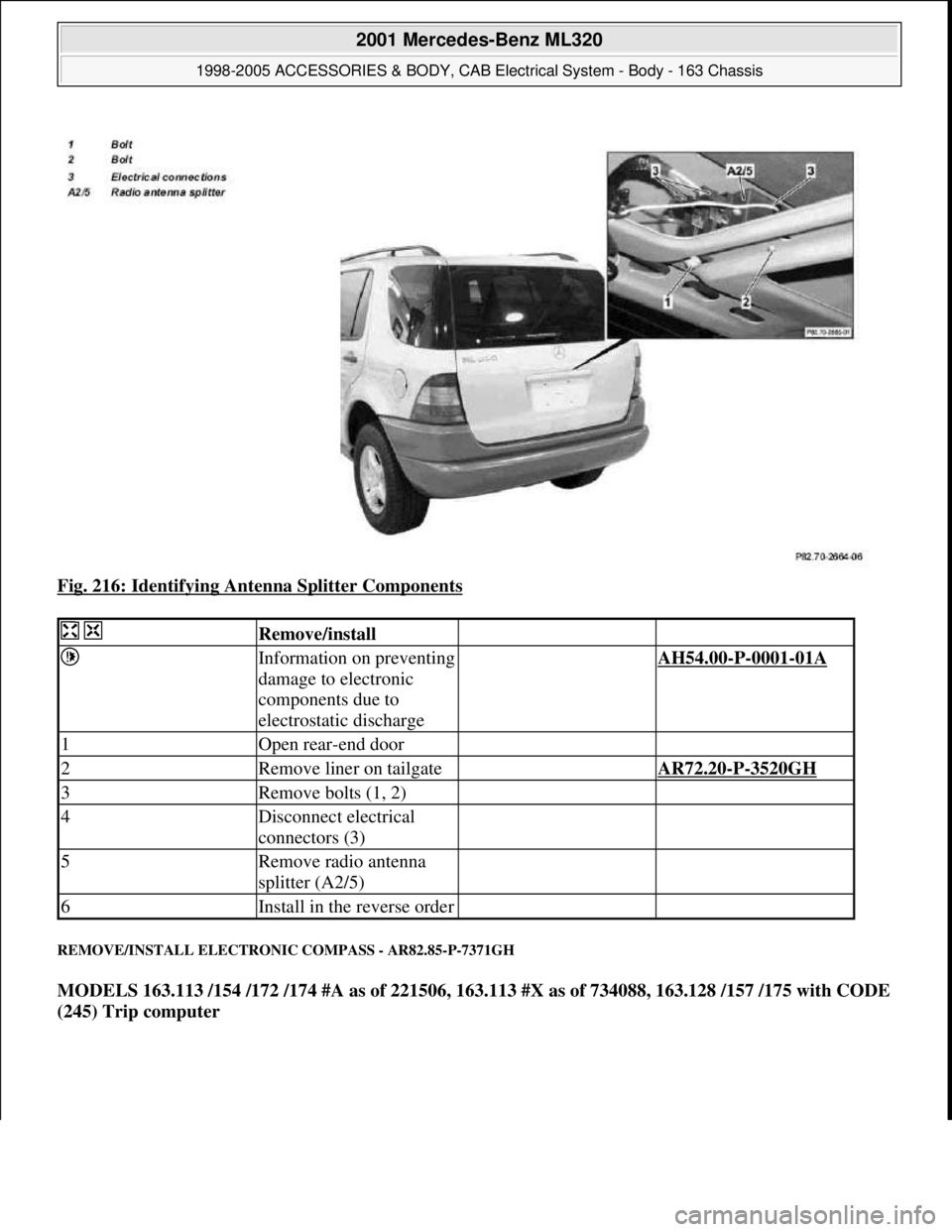
Fig. 216: Identifying Antenna Splitter Components
REMOVE/INSTALL ELECTRONIC COMPASS - AR82.85-P-7371GH
MODELS 163.113 /154 /172 /174 #A as of 221506, 163.113 #X as of 734088, 163.128 /157 /175 with CODE
(245) Trip computer
Remove/install
Information on preventing
damage to electronic
components due to
electrostatic discharge AH54.00-P-0001-01A
1Open rear-end door
2Remove liner on tailgate AR72.20-P-3520GH
3Remove bolts (1, 2)
4Disconnect electrical
connectors (3)
5Remove radio antenna
splitter (A2/5)
6Install in the reverse order
2001 Mercedes-Benz ML320
1998-2005 ACCESSORIES & BODY, CAB Electrical System - Body - 163 Chassis
me
Saturday, October 02, 2010 3:30:10 PMPage 316 © 2006 Mitchell Repair Information Company, LLC.
Page 1812 of 4133
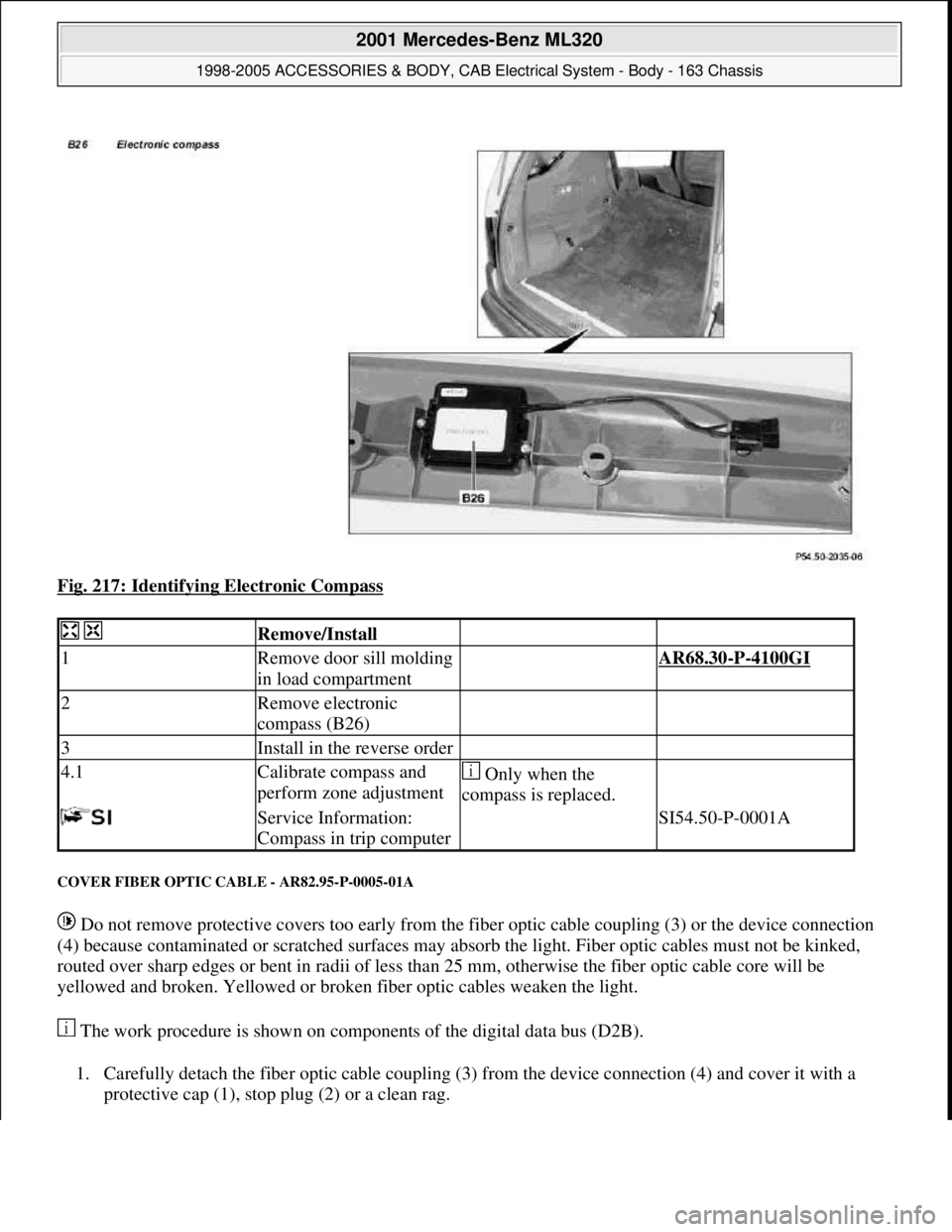
Fig. 217: Identifying Electronic Compass
COVER FIBER OPTIC CABLE - AR82.95-P-0005-01A
Do not remove protective covers too early from the fiber optic cable coupling (3) or the device connection
(4) because contaminated or scratched surfaces may absorb the light. Fiber optic cables must not be kinked,
routed over sharp edges or bent in radii of less than 25 mm, otherwise the fiber optic cable core will be
yellowed and broken. Yellowed or broken fiber optic cables weaken the light.
The work procedure is shown on components of the digital data bus (D2B).
1. Carefully detach the fiber optic cable coupling (3) from the device connection (4) and cover it with a
protective cap (1), stop plug (2) or a clean rag.
Remove/Install
1Remove door sill molding
in load compartment AR68.30-P-4100GI
2Remove electronic
compass (B26)
3Install in the reverse order
4.1Calibrate compass and
perform zone adjustment Only when the
compass is replaced.
Service Information:
Compass in trip computer SI54.50-P-0001A
2001 Mercedes-Benz ML320
1998-2005 ACCESSORIES & BODY, CAB Electrical System - Body - 163 Chassis
me
Saturday, October 02, 2010 3:30:10 PMPage 317 © 2006 Mitchell Repair Information Company, LLC.
Page 2065 of 4133

SI54.50-P-0001A
Service Information: Compass in trip computer
22.10.00
MODELS
163.113 /154 /172 as of 1.9.00,
163.128 /157 /174 /175 with CODE (245) Trip computer
The compass is calibrated in the factory in order to compensate
for deviations caused by magnetic field intensity of the vehicle and
magnetic interference when operating the heated rear window.
Once the compass is calibrated, it never needs to be recalibrated
under normal operating conditions. If a strong deviation in magnetic
field intensity is detected, the compass automatically recalibrates
itself.
A calibration must be carried out if the compass is replaced.
Additionally, the user can fine tune the compass in order to adapt
it to the vehicle's surrounding area. By setting the respective
compass zone, the compass compensates for deviations in the
earth's magnetic field.
The calibration should take place at least 10 m from any source of
interference such as power lines, buildings and parked vehicles.
Zone setting
1
Press the MODE button on the trip computer
until the compass direction is displayed
2
Press the RESET button once
The current compass zone is displayed
3
Press the RESET button until the desired
compass zone is displayed
The maps for determining the correct
compass zone can be found in the owner's
manual. If the RESET button is not pressed
within 5 seconds, the point of the compass is
displayed again.
Compass calibration
4
Bring the compass to the compass zone
display mode
5
Press the MODE button once
Display shows
CAL-
on.
6
Press the RESET button for at least 2 seconds
The hyphen (
-
) in the display disappears.
The calibration mode is active and remains
active until the calibration process has
concluded. If the ignition is switched off and
on, calibration mode remains active, even if
CAL
no longer is displayed.
7
Drive two complete circles at a speed of
between 5 - 10 km/h
Heated rear window switched off.
8
Switch heated rear window on
9
Drive three full circles at a speed from 5 - 10
km/h.
Calibration process concluded.
Although the display can change from
CAL
to
the point of the compass before the
calibration drive has been concluded, the
calibration process is still active and must be
carried out exactly as described.
Copyright DaimlerChrysler AG 18.05.2006 CD-Ausgabe G/10/04 . This WIS print-out will not be recorde
d by Modification services.
Page 1
Page 2125 of 4133
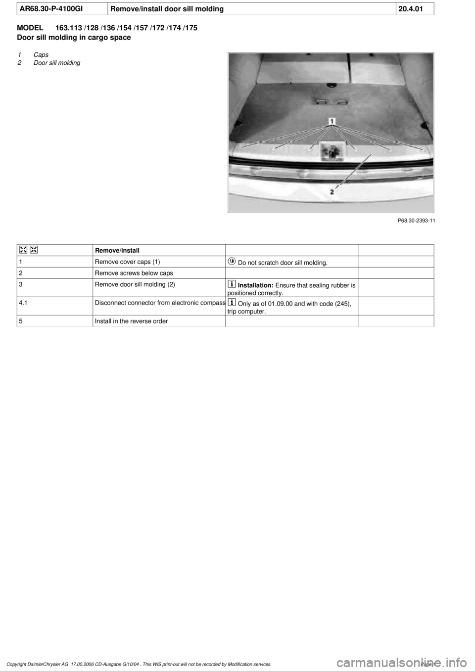
AR68.30-P-4100GI
Remove/install door sill molding
20.4.01
MODEL
163.113 /128 /136 /154 /157 /172 /174 /175
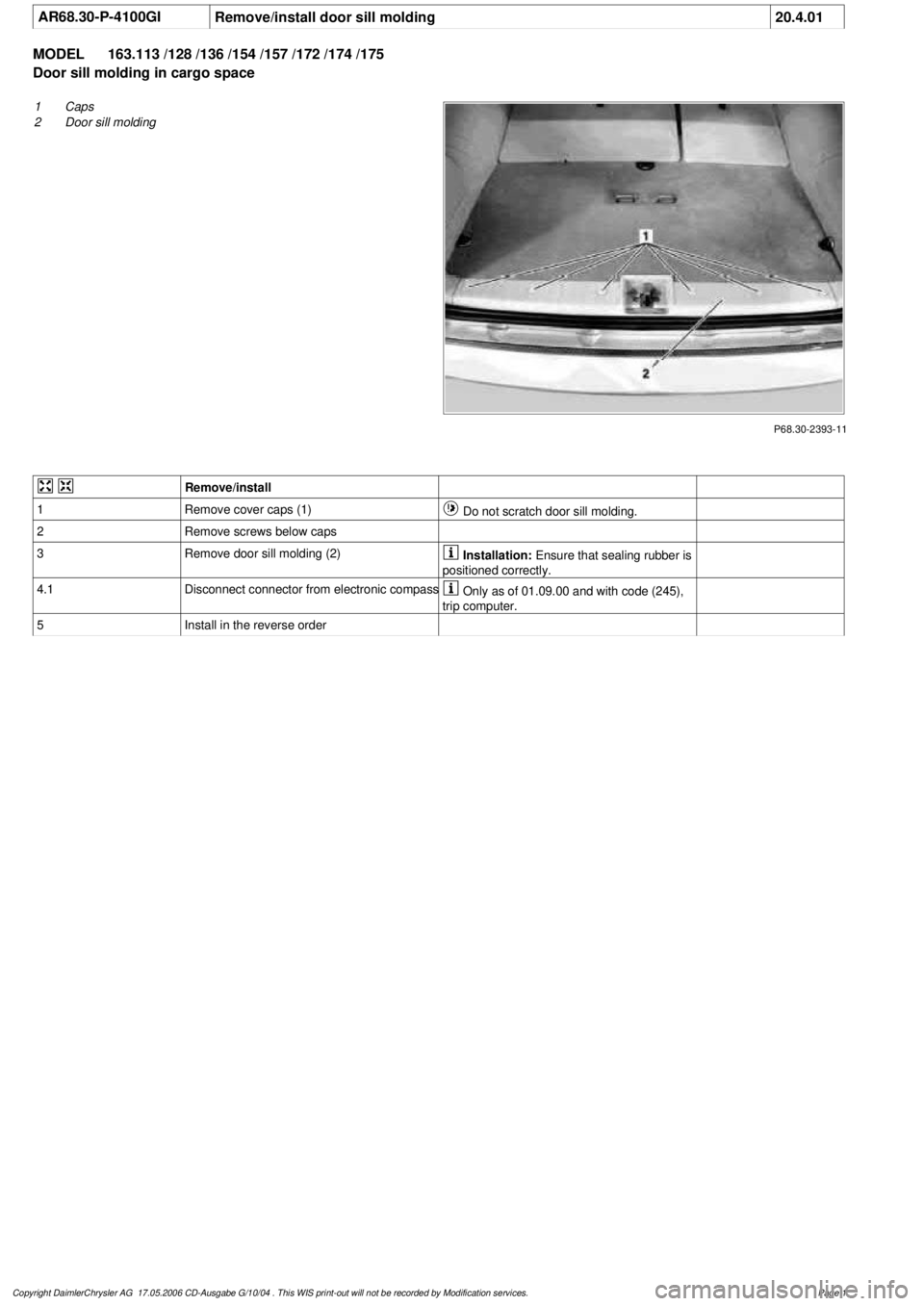
Door sill molding in cargo space
P68.30-2393-11
1
Caps
2
Door sill molding
Remove/install
1
Remove cover caps (1)
Do not scratch door sill molding.
2
Remove screws below caps
3
Remove door sill molding (2)
Installation:
Ensure that sealing rubber is
positioned correctly.
4.1
Disconnect connector from electronic compass
Only as of 01.09.00 and with code (245),
trip computer.
5
Install in the reverse order
Copyright DaimlerChrysler AG 17.05.2006 CD-Ausgabe G/10/04 . This WIS print-out will not be recorde
d by Modification services.
Page 1
Page 2126 of 4133
AR68.30-P-4100GI
Remove/install door sill molding
20.4.01
MODEL
163.113 /128 /136 /154 /157 /172 /174 /175
Door sill molding in cargo space
P68.30-2393-11
1
Caps
2
Door sill molding
Remove/install
1
Remove cover caps (1)
Do not scratch door sill molding.
2
Remove screws below caps
3
Remove door sill molding (2)
Installation:
Ensure that sealing rubber is
positioned correctly.
4.1
Disconnect connector from electronic compass
Only as of 01.09.00 and with code (245),
trip computer.
5
Install in the reverse order
Copyright DaimlerChrysler AG 17.05.2006 CD-Ausgabe G/10/04 . This WIS print-out will not be recorde
d by Modification services.
Page 1
Page 2130 of 4133
AR68.30-P-4100GI
Remove/install door sill molding
20.4.01
MODEL
163.113 /128 /136 /154 /157 /172 /174 /175
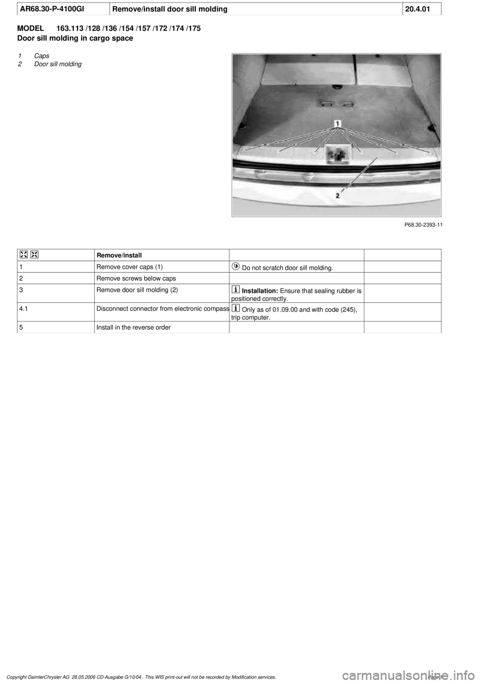
Door sill molding in cargo space
P68.30-2393-11
1
Caps
2
Door sill molding
Remove/install
1
Remove cover caps (1)
Do not scratch door sill molding.
2
Remove screws below caps
3
Remove door sill molding (2)
Installation:
Ensure that sealing rubber is
positioned correctly.
4.1
Disconnect connector from electronic compass
Only as of 01.09.00 and with code (245),
trip computer.
5
Install in the reverse order
Copyright DaimlerChrysler AG 28.05.2006 CD-Ausgabe G/10/04 . This WIS print-out will not be recorde
d by Modification services.
Page 1