MERCEDES-BENZ R-Class 2011 W251 Owner's Manual
Manufacturer: MERCEDES-BENZ, Model Year: 2011, Model line: R-Class, Model: MERCEDES-BENZ R-Class 2011 W251Pages: 364, PDF Size: 16.5 MB
Page 291 of 364
Cleaning the seat beltsXUse clean, luke-warm water and soap
solution.
! Do not clean the seat belts using chemical
cleaning agents. Do not dry the seat belts
by warming them above 176 ‡ (80 †) or
placing them in direct sunlight.
GWarning
Do not bleach or dye seat belts as this may
severely weaken them. In a crash, they may
not be able to provide adequate protection.
Cleaning the headliner and carpets
XRoof lining: use soft brushes or dry
shampoo if it is particularly dirty.XCarpets: use carpet and textile cleaners
that have been approved and
recommended by Mercedes-Benz.Care289Maintenance and careBA 251 USA, CA Edition A 2011; 1; 3, en-USd2sboikeVersion: 3.0.3.52010-04-16T14:31:55+02:00 - Seite 289Z
Page 292 of 364

290BA 251 USA, CA Edition A 2011; 1; 3, en-USd2sboikeVersion: 3.0.3.52010-04-16T14:31:55+02:00 - Seite 290
Page 293 of 364
Vehicle equipment ............................292
After an accident .............................. 293
Where will I find...? ...........................293
Flat tire .............................................. 296
Battery ............................................... 308
Jump-starting .................................... 311
Towing away ..................................... 313
Fuses .................................................. 315291Roadside AssistanceBA 251 USA, CA Edition A 2011; 1; 3, en-USd2sboikeVersion: 3.0.3.52010-04-16T14:31:55+02:00 - Seite 291
Page 294 of 364
Vehicle equipment
i This manual describes all the standard
and optional equipment of your vehicle
which was available at the time of
purchase. Country-specific differences are
possible. Bear in mind that your vehicle
may not feature all functions described
here. This also refers to safety-related
systems and functions.292Vehicle equipmentRoadside Assistance
BA 251 USA, CA Edition A 2011; 1; 3, en-USd2sboikeVersion: 3.0.3.52010-04-16T14:31:55+02:00 - Seite 292
Page 295 of 364
After an accidentProblemPossible causes/consequences and M SolutionsFuel is leaking from the
vehicle.GRisk of explosion or fire
The fuel line or the fuel tank is faulty.
XImmediately turn the SmartKey to position 0 ( Y page 149) in the
ignition lock and remove it.XDo not restart the engine under any circumstances.XConsult a qualified specialist workshop.You are unable to
determine the extent of
the damage.XConsult a qualified specialist workshop.You cannot detect any
damage.XStart the engine as normal.The NECK-PRO head
restraints/NECK-PRO
luxury head restraints
on the driver's and
front-passenger seat
have been triggered.Your vehicle has been involved in a rear-end collision.XReset the NECK-PRO head restraints/NECK-PRO luxury head
restraints ( Y page 53).Where will I find...?
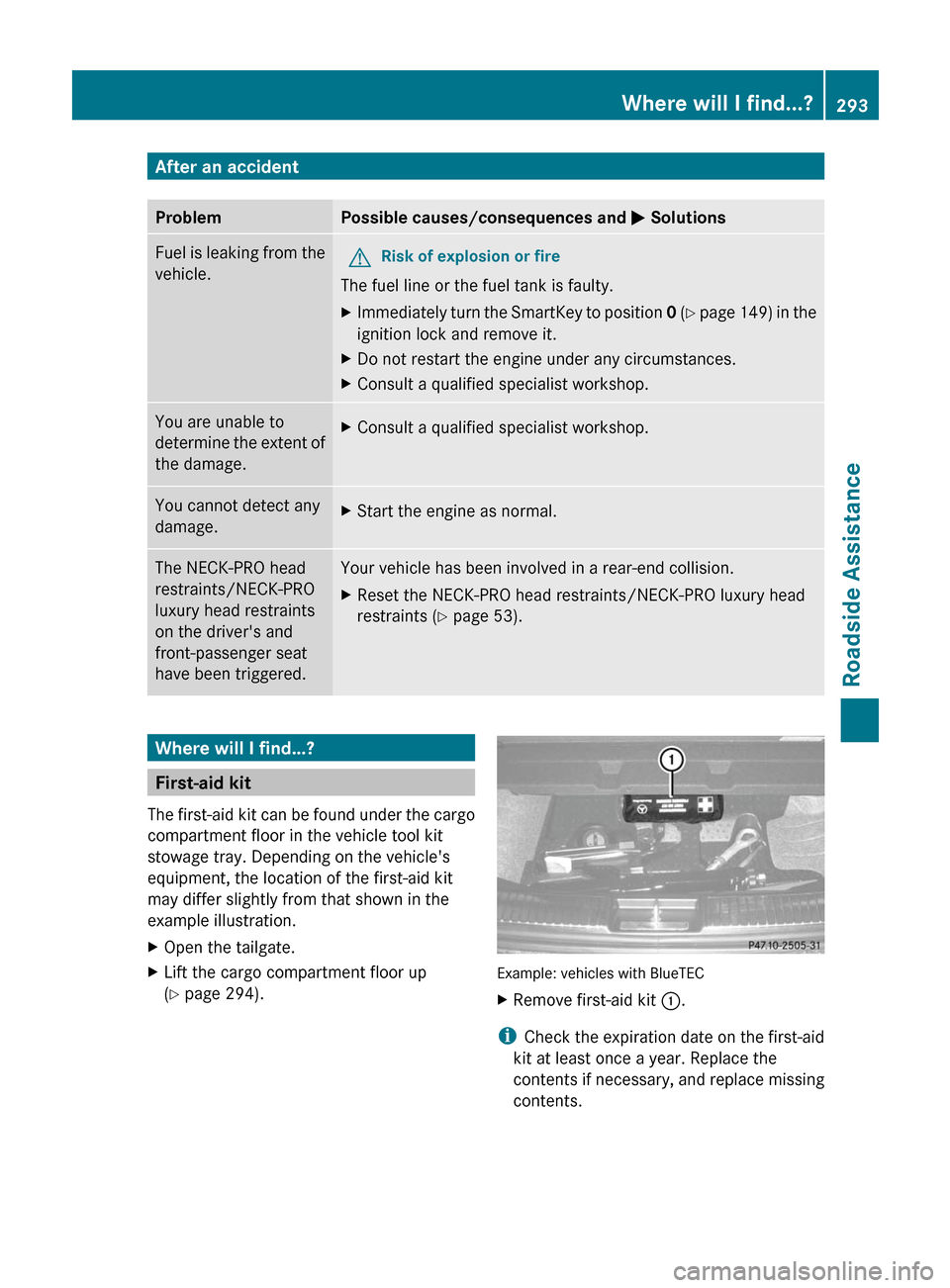
First-aid kit
The first-aid kit can be found under the cargo
compartment floor in the vehicle tool kit
stowage tray. Depending on the vehicle's
equipment, the location of the first-aid kit
may differ slightly from that shown in the
example illustration.
XOpen the tailgate.XLift the cargo compartment floor up
( Y page 294).
Example: vehicles with BlueTEC
XRemove first-aid kit :.
i
Check the expiration date on the first-aid
kit at least once a year. Replace the
contents if necessary, and replace missing
contents.
Where will I find...?293Roadside AssistanceBA 251 USA, CA Edition A 2011; 1; 3, en-USd2sboikeVersion: 3.0.3.52010-04-16T14:31:55+02:00 - Seite 293Z
Page 296 of 364
Vehicle tool kit
Notes
The vehicle tool kit can be found in the
stowage well under the cargo compartment
floor.
i Vehicles are not equipped with the tools
needed to change a wheel when they leave
the factory, e.g. jack or lug wrench. Some
tools for changing a wheel are specific to
the vehicle. To obtain tools approved for
your vehicle, visit a qualified specialist
workshop, e.g. an authorized Mercedes-
Benz Center.
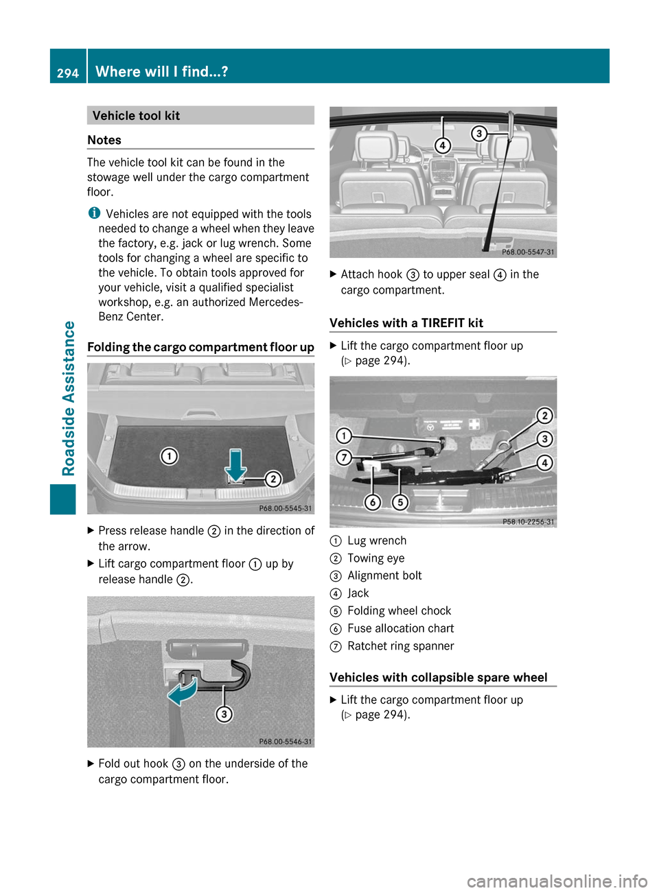
Folding the cargo compartment floor up
XPress release handle ; in the direction of
the arrow.XLift cargo compartment floor : up by
release handle ;.XFold out hook = on the underside of the
cargo compartment floor.XAttach hook = to upper seal ? in the
cargo compartment.
Vehicles with a TIREFIT kit
XLift the cargo compartment floor up
( Y page 294).:Lug wrench;Towing eye=Alignment bolt?JackAFolding wheel chockBFuse allocation chartCRatchet ring spanner
Vehicles with collapsible spare wheel
XLift the cargo compartment floor up
( Y page 294).294Where will I find...?Roadside Assistance
BA 251 USA, CA Edition A 2011; 1; 3, en-USd2sboikeVersion: 3.0.3.52010-04-16T14:31:55+02:00 - Seite 294
Page 297 of 364
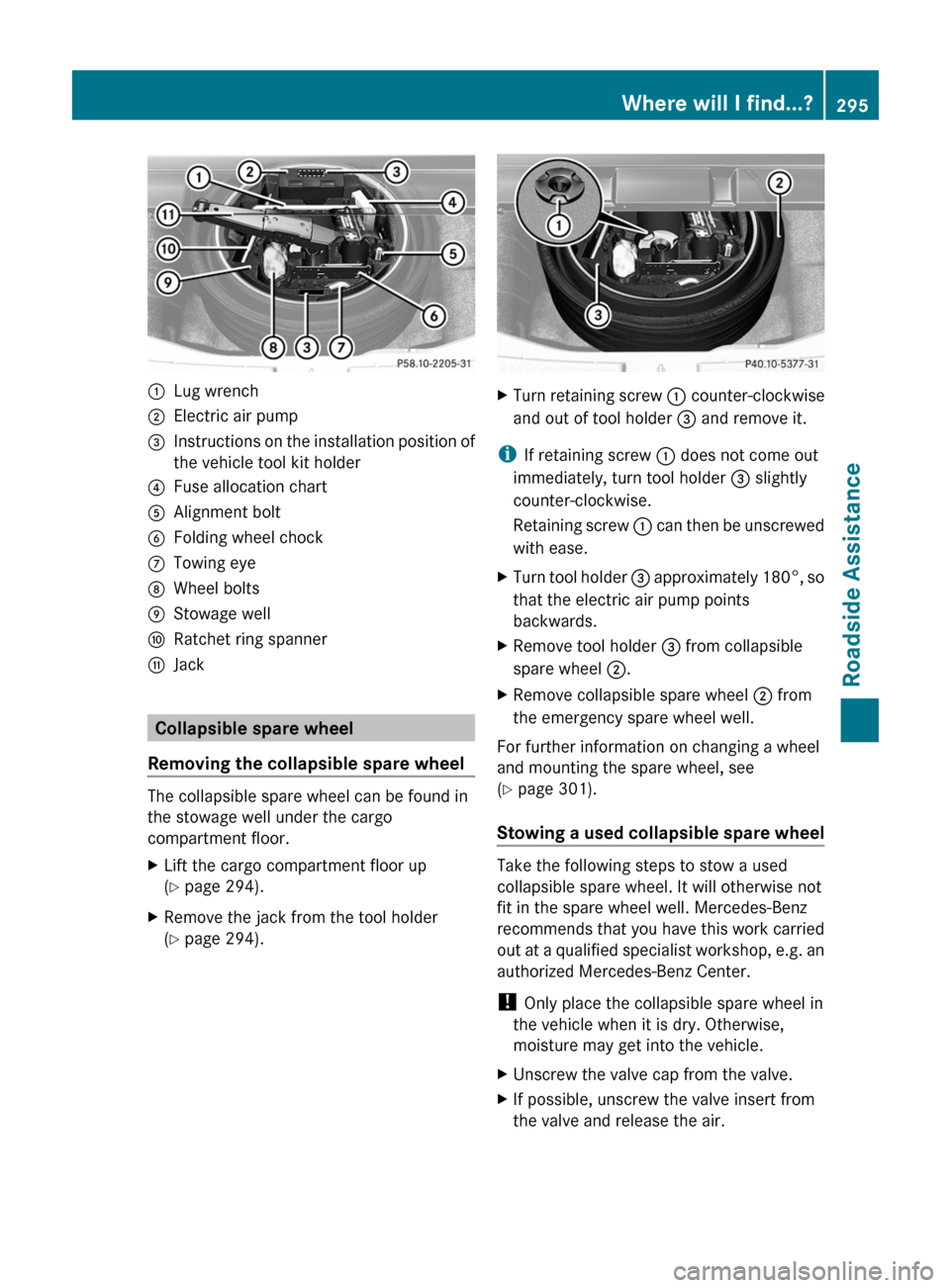
:Lug wrench;Electric air pump=Instructions on the installation position of
the vehicle tool kit holder?Fuse allocation chartAAlignment boltBFolding wheel chockCTowing eyeDWheel boltsEStowage wellFRatchet ring spannerGJack
Collapsible spare wheel
Removing the collapsible spare wheel
The collapsible spare wheel can be found in
the stowage well under the cargo
compartment floor.
XLift the cargo compartment floor up
( Y page 294).XRemove the jack from the tool holder
( Y page 294).XTurn retaining screw : counter-clockwise
and out of tool holder = and remove it.
i
If retaining screw : does not come out
immediately, turn tool holder = slightly
counter-clockwise.
Retaining screw : can then be unscrewed
with ease.
XTurn tool holder = approximately 180°, so
that the electric air pump points
backwards.XRemove tool holder = from collapsible
spare wheel ;.XRemove collapsible spare wheel ; from
the emergency spare wheel well.
For further information on changing a wheel
and mounting the spare wheel, see
( Y page 301).
Stowing a used collapsible spare wheel
Take the following steps to stow a used
collapsible spare wheel. It will otherwise not
fit in the spare wheel well. Mercedes-Benz
recommends that you have this work carried
out at a qualified specialist workshop, e.g. an
authorized Mercedes-Benz Center.
! Only place the collapsible spare wheel in
the vehicle when it is dry. Otherwise,
moisture may get into the vehicle.
XUnscrew the valve cap from the valve.XIf possible, unscrew the valve insert from
the valve and release the air.Where will I find...?295Roadside AssistanceBA 251 USA, CA Edition A 2011; 1; 3, en-USd2sboikeVersion: 3.0.3.52010-04-16T14:31:55+02:00 - Seite 295Z
Page 298 of 364
iFully deflating the tire can take a few
minutes.XScrew the valve insert back into the valve.XScrew the valve cap back on.
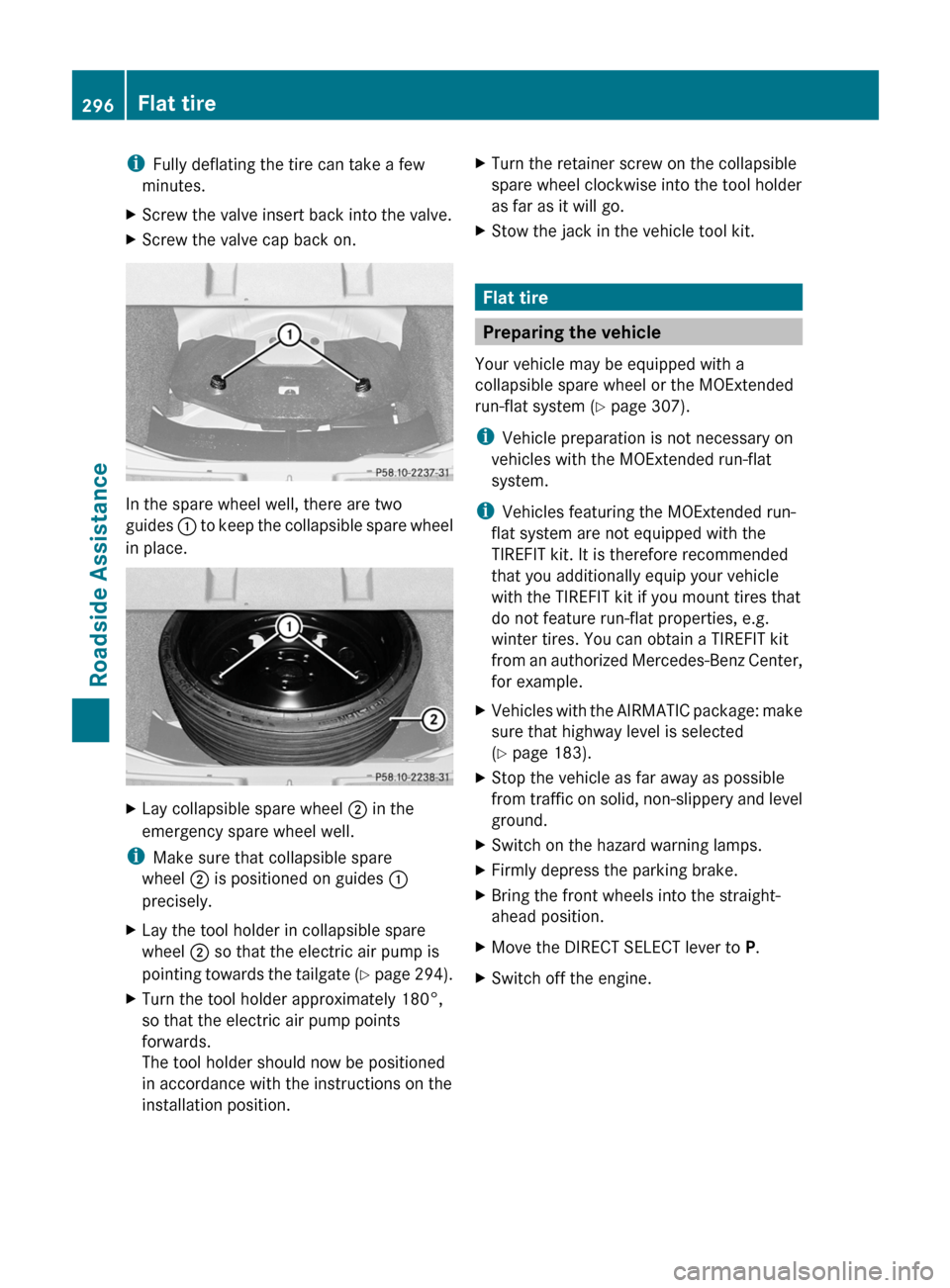
In the spare wheel well, there are two
guides : to keep the collapsible spare wheel
in place.
XLay collapsible spare wheel ; in the
emergency spare wheel well.
i Make sure that collapsible spare
wheel ; is positioned on guides :
precisely.
XLay the tool holder in collapsible spare
wheel ; so that the electric air pump is
pointing towards the tailgate (Y page 294).XTurn the tool holder approximately 180°,
so that the electric air pump points
forwards.
The tool holder should now be positioned
in accordance with the instructions on the
installation position.XTurn the retainer screw on the collapsible
spare wheel clockwise into the tool holder
as far as it will go.XStow the jack in the vehicle tool kit.
Flat tire
Preparing the vehicle
Your vehicle may be equipped with a
collapsible spare wheel or the MOExtended
run-flat system ( Y page 307).
i Vehicle preparation is not necessary on
vehicles with the MOExtended run-flat
system.
i Vehicles featuring the MOExtended run-
flat system are not equipped with the
TIREFIT kit. It is therefore recommended
that you additionally equip your vehicle
with the TIREFIT kit if you mount tires that
do not feature run-flat properties, e.g.
winter tires. You can obtain a TIREFIT kit
from an authorized Mercedes-Benz Center,
for example.
XVehicles with the AIRMATIC package: make
sure that highway level is selected
( Y page 183).XStop the vehicle as far away as possible
from traffic on solid, non-slippery and level
ground.XSwitch on the hazard warning lamps.XFirmly depress the parking brake.XBring the front wheels into the straight-
ahead position.XMove the DIRECT SELECT lever to P.XSwitch off the engine.296Flat tireRoadside Assistance
BA 251 USA, CA Edition A 2011; 1; 3, en-USd2sboikeVersion: 3.0.3.52010-04-16T14:31:55+02:00 - Seite 296
Page 299 of 364
XVehicles without KEYLESS-GO: remove
the key from the ignition lock.
XVehicles with KEYLESS-GO: open the
driver's door.
The on-board electronics have status 0,
which is the same as the key having been
removed.
XVehicles with KEYLESS-GO: remove the
Start/Stop button from the ignition lock
(Y page 149).
XAll occupants must get out of the vehicle.
Make sure that they are not endangered as
they do so.
XMake sure that no one is near the danger
area whilst a wheel is being changed.
Anyone who is not directly assisting in the
wheel change should, for example, stand
behind the barrier.
XGet out of the vehicle. Pay attention to
traffic conditions when doing so.
XClose the driver's door.
iOnly operate the electric air pump using
the socket in the footwell of the second row
of seats (Y page 265), even if the ignition
is turned off.
An emergency cut-off ensures that the on-
board voltage does not drop too low. If the
on-board voltage is too low, power to the
sockets is automatically cut-off. This
ensures that there is sufficient power to
start the engine.
TIREFIT kit
Using the TIREFIT kit
You can use the TIREFIT kit to seal small
punctures, particularly those in the tire tread.
You can use TIREFIT at outside temperatures
down to -4 ‡ (-20 †).
GWarning
TIREFIT is a limited repair device. TIREFIT
cannot be used for cuts or punctures larger
than approximately 0.16 in (4 mm) and tire
damage caused by driving with extremely low
tire inflation pressure, or on a flat tire, or a
damaged wheel.
Do not drive the vehicle under such
circumstances.
Contact the nearest authorized Mercedes-
Benz Center for assistance or call roadside
assistance.
XDo not remove any foreign objects which
have penetrated the tire, e.g. screws or
nails.
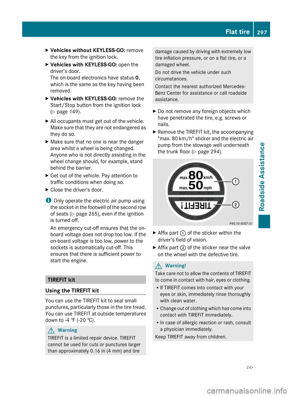
XRemove the TIREFIT kit, the accompanying
"max. 80 km/h" sticker and the electric air
pump from the stowage well underneath
the trunk floor (Y page 294).
XAffix part : of the sticker within the
driver's field of vision.
XAffix part ; of the sticker near the valve
on the wheel with the defective tire.
GWarning!
Take care not to allow the contents of TIREFIT
to come in contact with hair, eyes or clothing.
RIf TIREFIT comes into contact with your
eyes or skin, immediately rinse thoroughly
with clean water.
RChange out of clothing which has come into
contact with TIREFIT immediately.
RIn case of allergic reaction or rash, consult
a physician immediately.
Keep TIREFIT away from children.
Flat tire297Roadside AssistanceBA 251 USA, CA Edition A 2011; 1; 3, en-USd2sboikeVersion: 3.0.3.52010-04-16T14:31:55+02:00 - Seite 297Z
Page 300 of 364
RIf TIREFIT is swallowed, immediately rinse
your mouth out thoroughly with water and
drink plenty of water.
RDo not induce vomiting. Consult a doctor
immediately.
RDo not inhale TIREFIT fumes.
iIf TIREFIT leaks out, allow it to dry. It can
then be removed like a layer of film.
If you get TIREFIT on your clothing, have it
cleaned as soon as possible with
perchloroethylene.
GWarning!
Comply with the manufacturer's safety
instructions on the sticker on the electric air
pump.
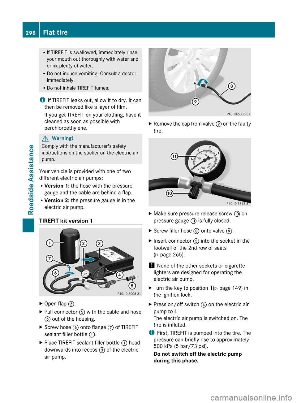
Your vehicle is provided with one of two
different electric air pumps:
RVersion 1: the hose with the pressure
gauge and the cable are behind a flap.
RVersion 2: the pressure gauge is in the
electric air pump.
TIREFIT kit version 1
XOpen flap ;.XPull connector A with the cable and hose
B out of the housing.
XScrew hose B onto flange C of TIREFIT
sealant filler bottle :.
XPlace TIREFIT sealant filler bottle : head
downwards into recess = of the electric
air pump.
XRemove the cap from valve E on the faulty
tire.
XMake sure pressure release screw F on
pressure gauge G is fully closed.
XScrew filler hose D onto valve E.XInsert connector A into the socket in the
footwell of the 2nd row of seats
(Y page 265).
! None of the other sockets or cigarette
lighters are designed for operating the
electric air pump.
XTurn the key to position 1(Y page 149) in
the ignition lock.
XPress on/off switch ? on the electric air
pump to I.
The electric air pump is switched on. The
tire is inflated.
iFirst, TIREFIT is pumped into the tire. The
pressure can briefly rise to approximately
500 kPa (5 bar/73 psi).
Do not switch off the electric pump
during this phase.
298Flat tireRoadside Assistance
BA 251 USA, CA Edition A 2011; 1; 3, en-USd2sboikeVersion: 3.0.3.52010-04-16T14:31:55+02:00 - Seite 298