MERCEDES-BENZ R-Class 2011 W251 Owner's Manual
Manufacturer: MERCEDES-BENZ, Model Year: 2011, Model line: R-Class, Model: MERCEDES-BENZ R-Class 2011 W251Pages: 364, PDF Size: 16.5 MB
Page 301 of 364
XLet the electric pump run for five minutes.
The tire should then have attained a
pressure of at least 180 kPa (1.8 bar/
26 psi).
GWarning
The air hose can become hot during inflation.
Please exercise appropriate caution.
! Do not operate the electric air pump for
longer than eight minutes at a time without
a break. It may otherwise overheat.
The air pump can be operated again once
it has cooled down.
If after five minutes a pressure of 180 kPa
(1.8 bar/26 psi) has been achieved, see
(Y page 300).
If after five minutes a pressure of 180 kPa
(1.8 bar/26 psi) has not been achieved, see
(Y page 300).
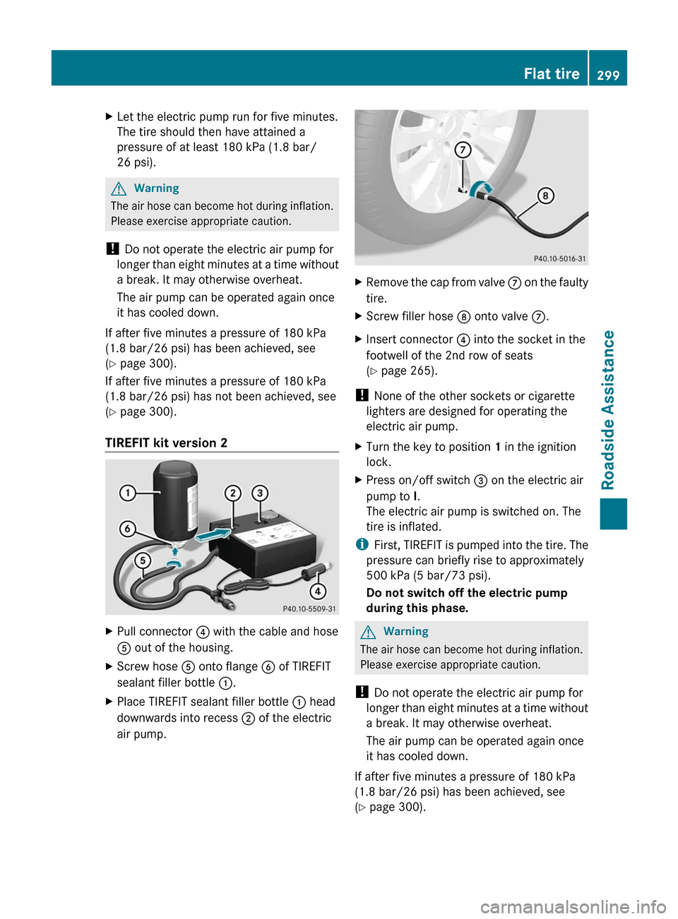
TIREFIT kit version 2
XPull connector ? with the cable and hose
A out of the housing.
XScrew hose A onto flange B of TIREFIT
sealant filler bottle :.
XPlace TIREFIT sealant filler bottle : head
downwards into recess ; of the electric
air pump.
XRemove the cap from valve C on the faulty
tire.
XScrew filler hose D onto valve C.XInsert connector ? into the socket in the
footwell of the 2nd row of seats
(Y page 265).
! None of the other sockets or cigarette
lighters are designed for operating the
electric air pump.
XTurn the key to position 1 in the ignition
lock.
XPress on/off switch = on the electric air
pump to I.
The electric air pump is switched on. The
tire is inflated.
iFirst, TIREFIT is pumped into the tire. The
pressure can briefly rise to approximately
500 kPa (5 bar/73 psi).
Do not switch off the electric pump
during this phase.
GWarning
The air hose can become hot during inflation.
Please exercise appropriate caution.
! Do not operate the electric air pump for
longer than eight minutes at a time without
a break. It may otherwise overheat.
The air pump can be operated again once
it has cooled down.
If after five minutes a pressure of 180 kPa
(1.8 bar/26 psi) has been achieved, see
(Y page 300).
Flat tire299Roadside AssistanceBA 251 USA, CA Edition A 2011; 1; 3, en-USd2sboikeVersion: 3.0.3.52010-04-16T14:31:55+02:00 - Seite 299Z
Page 302 of 364
If after five minutes a pressure of 180 kPa
(1.8 bar/26 psi) has not been achieved, see
( Y page 300).
Tire pressure of 180 kPa (1.8 bar/
26 psi) is not achieved
If after five minutes a pressure of 180 kPa
(1.8 bar/26 psi) has not been achieved:
XPress the on/off switch on the electric air
pump to 0.
The electric air pump is switched off.XUnscrew the filler hose from the valve.XVery slowly drive forwards or reverse
approximately 30 ft (10 m).XPump up the tire again.GWarning
If after five minutes a pressure of 180 kPa
(1.8 bar/26 psi) cannot be achieved, the tire
is too badly damaged to be repaired reliably
using TIREFIT.
In this case TIREFIT cannot seal the tire
properly.
Do not drive any further.
Contact the nearest authorized Mercedes-
Benz Center for assistance or call roadside
assistance.
Tire pressure of 180 kPa (1.8 bar/
26 psi) is achieved
XPress the on/off switch on the electric air
pump to 0.
The electric air pump is switched off.XRemove the TIREFIT kit from the wheel.GWarning
The air hose may still be hot. Exercise proper
caution to avoid burning yourself when
detaching the electric air pump.
! After use, excess TIREFIT may run out of
the filler hose. This could cause stains.
Therefore, place the filler hose in the plastic
bag which contained the TIREFIT kit.
XStow the TIREFIT kit and the electric air
pump.XPull away immediately .GWarning
Do not exceed a vehicle speed of 50 mph
(80 km/h ). A TIREFIT repair is not designed to
operate at higher speeds.
The sticker must be attached on the
instrument cluster where it will be easily seen
by the driver.
Vehicle handling characteristics of a TIREFIT
repaired tire may change. Adapt your driving
accordingly.
XStop after driving for approximately ten
minutes and check the tire pressure with
the electric air pump.GWarning
If tire inflation pressure has fallen below
130 kPa (1.3 bar/26 psi) do not continue to
drive the vehicle.
Park your vehicle safely away from the
roadway and contact the nearest authorized
Mercedes-Benz Center or roadside
assistance.
Have the damaged tire replaced.
XCorrect the tire pressure if it is at least
130 kPa (1.3 bar/20 psi) (values can be
found in the tire and loading information
table on the B-pillar on the driver's side or
in the tire pressure table on the inside of
the fuel filler flap).XTo increase the tire pressure: switch on
the electric air pump.300Flat tireRoadside Assistance
BA 251 USA, CA Edition A 2011; 1; 3, en-USd2sboikeVersion: 3.0.3.52010-04-16T14:31:55+02:00 - Seite 300
Page 303 of 364
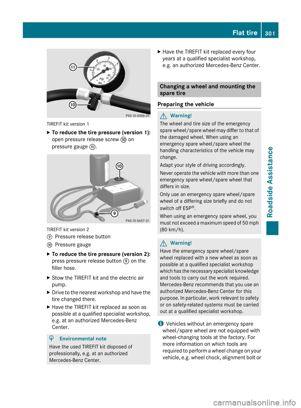
TIREFIT kit version 1
XTo reduce the tire pressure (version 1):
open pressure release screw F on
pressure gauge G.
TIREFIT kit version 2
EPressure release buttonFPressure gaugeXTo reduce the tire pressure (version 2):
press pressure release button E on the
filler hose.
XStow the TIREFIT kit and the electric air
pump.
XDrive to the nearest workshop and have the
tire changed there.
XHave the TIREFIT kit replaced as soon as
possible at a qualified specialist workshop,
e.g. at an authorized Mercedes-Benz
Center.
HEnvironmental note
Have the used TIREFIT kit disposed of
professionally, e.g. at an authorized
Mercedes-Benz Center.
XHave the TIREFIT kit replaced every four
years at a qualified specialist workshop,
e.g. an authorized Mercedes-Benz Center.
Changing a wheel and mounting the
spare tire
Preparing the vehicle
GWarning!
The wheel and tire size of the emergency
spare wheel/spare wheel may differ to that of
the damaged wheel. When using an
emergency spare wheel/spare wheel the
handling characteristics of the vehicle may
change.
Adapt your style of driving accordingly.
Never operate the vehicle with more than one
emergency spare wheel/spare wheel that
differs in size.
Only use an emergency spare wheel/spare
wheel of a differing size briefly and do not
switch off ESP®.
When using an emergency spare wheel, you
must not exceed a maximum speed of 50 mph
(80 km/h).
GWarning!
Have the emergency spare wheel/spare
wheel replaced with a new wheel as soon as
possible at a qualified specialist workshop
which has the necessary specialist knowledge
and tools to carry out the work required.
Mercedes-Benz recommends that you use an
authorized Mercedes-Benz Center for this
purpose. In particular, work relevant to safety
or on safety-related systems must be carried
out at a qualified specialist workshop.
iVehicles without an emergency spare
wheel/spare wheel are not equipped with
wheel-changing tools at the factory. For
more information on which tools are
required to perform a wheel change on your
vehicle, e.g. wheel chock, alignment bolt or
Flat tire301Roadside AssistanceBA 251 USA, CA Edition A 2011; 1; 3, en-USd2sboikeVersion: 3.0.3.52010-04-16T14:31:55+02:00 - Seite 301Z
Page 304 of 364
lug wrench, consult an authorized
Mercedes-Benz Center.
XPrepare the vehicle as described
(Y page 296).
XIf a trailer is coupled to the vehicle,
uncouple it.
XRemove the following items from the
stowage well under the trunk floor:
Rthe emergency spare wheel40
Rthe wheel bolts for the emergency spare
wheel40
Rthe jack
Rthe ratchet ring spanner
Rthe lug wrench
Rthe folding wheel chock
Rthe alignment bolt
Rthe electric air pump40
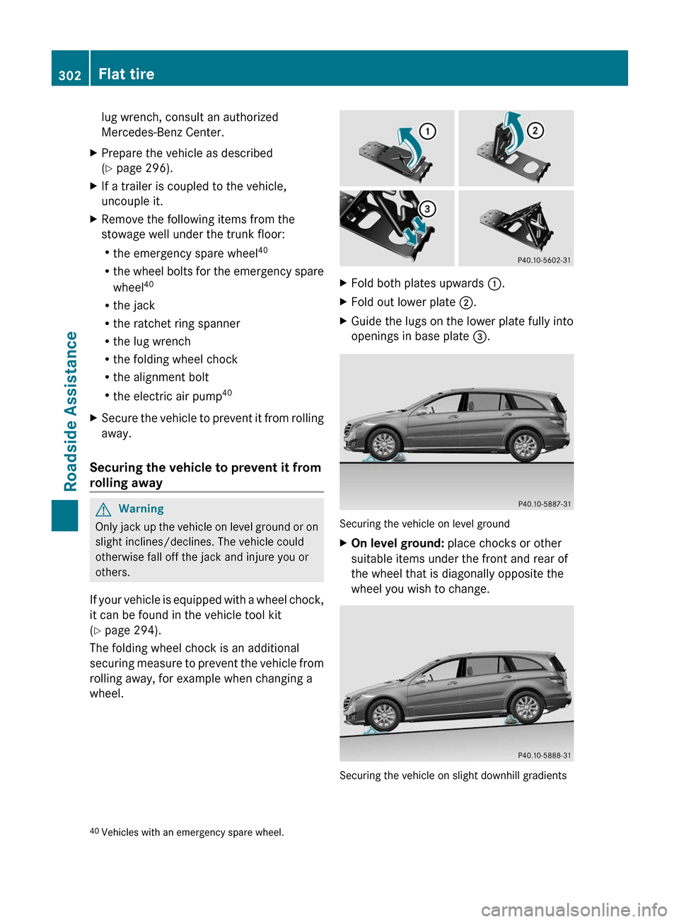
XSecure the vehicle to prevent it from rolling
away.
Securing the vehicle to prevent it from
rolling away
GWarning
Only jack up the vehicle on level ground or on
slight inclines/declines. The vehicle could
otherwise fall off the jack and injure you or
others.
If your vehicle is equipped with a wheel chock,
it can be found in the vehicle tool kit
(Y page 294).
The folding wheel chock is an additional
securing measure to prevent the vehicle from
rolling away, for example when changing a
wheel.
XFold both plates upwards :.XFold out lower plate ;.XGuide the lugs on the lower plate fully into
openings in base plate =.
Securing the vehicle on level ground
XOn level ground: place chocks or other
suitable items under the front and rear of
the wheel that is diagonally opposite the
wheel you wish to change.
Securing the vehicle on slight downhill gradients
40Vehicles with an emergency spare wheel.302Flat tireRoadside Assistance
BA 251 USA, CA Edition A 2011; 1; 3, en-USd2sboikeVersion: 3.0.3.52010-04-16T14:31:55+02:00 - Seite 302
Page 305 of 364
XOn downhill gradients: place chocks or
other suitable items in front of the wheels
of the front and rear axle.
Raising the vehicle
GWarning
When jacking up the vehicle, only use the jack
which has been specifically approved by
Mercedes-Benz for your vehicle.
The jack is designed exclusively for jacking up
the vehicle at the jacking points built into both
sides of the vehicle. The jack saddle must be
placed centrally under the jacking point. The
jack must always be vertical when in use,
especially on inclines or declines.
The jack is intended only for lifting the vehicle
briefly for wheel changes. It is not suited for
performing maintenance work under the
vehicle. To help avoid personal injury, use the
jack only to lift the vehicle during a wheel
change.
Never get beneath the vehicle while it is
supported by the jack. Keep hands and feet
away from the area under the lifted vehicle.
Always lower the vehicle onto sufficient
capacity jackstands before working under the
vehicle.
Always firmly engage the parking brake and
block the wheels with wheel chocks or other
sizable objects before raising the vehicle with
the jack. Do not disengage the parking brake
while the vehicle is raised.
Make sure that the ground on which the
vehicle is standing and where you place the
jack is solid, level and not slippery. If
necessary, use a large underlay. On slippery
surfaces, such as tiled floors, you should use
a non-slip underlay, for example a rubber mat.
Do not use wooden blocks or similar objects
as a jack underlay. Otherwise, the jack may
not be able to achieve its load-bearing
capacity if it is not at its full height.
Never start the engine when the vehicle is
raised.
Also observe the notes on the jack.
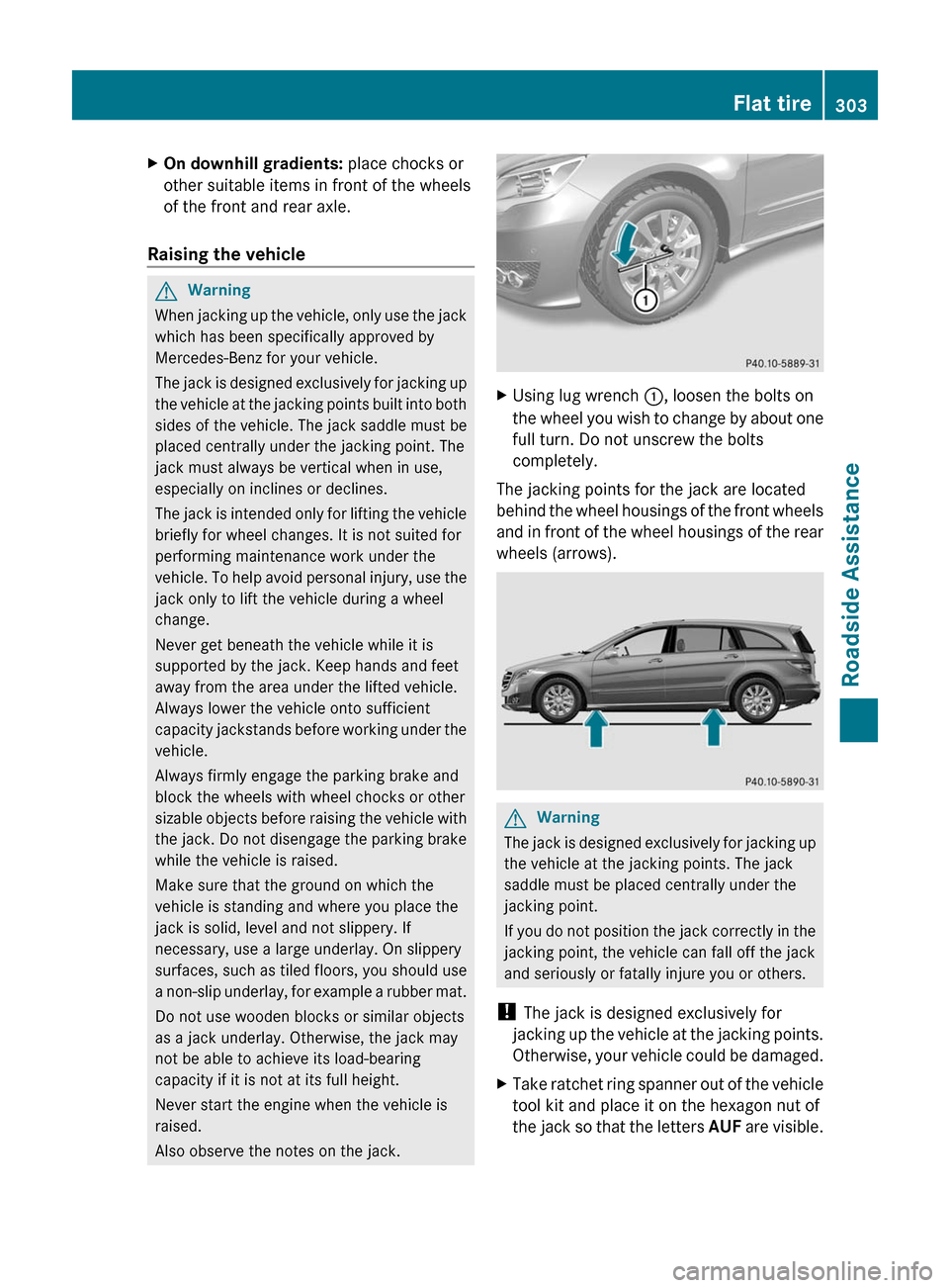
XUsing lug wrench :, loosen the bolts on
the wheel you wish to change by about one
full turn. Do not unscrew the bolts
completely.
The jacking points for the jack are located
behind the wheel housings of the front wheels
and in front of the wheel housings of the rear
wheels (arrows).
GWarning
The jack is designed exclusively for jacking up
the vehicle at the jacking points. The jack
saddle must be placed centrally under the
jacking point.
If you do not position the jack correctly in the
jacking point, the vehicle can fall off the jack
and seriously or fatally injure you or others.
! The jack is designed exclusively for
jacking up the vehicle at the jacking points.
Otherwise, your vehicle could be damaged.
XTake ratchet ring spanner out of the vehicle
tool kit and place it on the hexagon nut of
the jack so that the letters AUF are visible.Flat tire303Roadside AssistanceBA 251 USA, CA Edition A 2011; 1; 3, en-USd2sboikeVersion: 3.0.3.52010-04-16T14:31:55+02:00 - Seite 303Z
Page 306 of 364
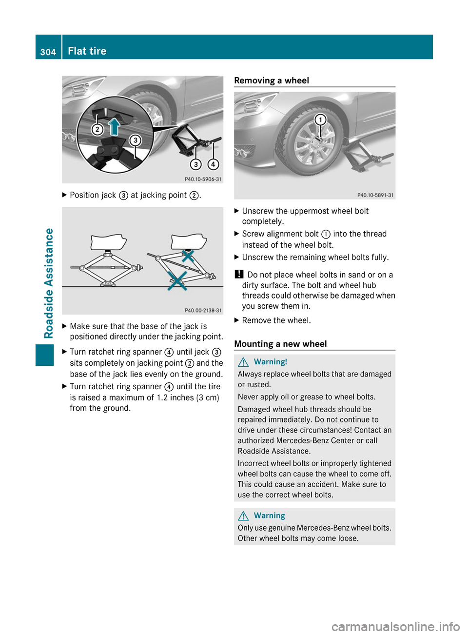
XPosition jack = at jacking point ;.XMake sure that the base of the jack is
positioned directly under the jacking point.XTurn ratchet ring spanner ? until jack =
sits completely on jacking point ; and the
base of the jack lies evenly on the ground.XTurn ratchet ring spanner ? until the tire
is raised a maximum of 1.2 inches (3 cm)
from the ground.Removing a wheelXUnscrew the uppermost wheel bolt
completely.XScrew alignment bolt : into the thread
instead of the wheel bolt.XUnscrew the remaining wheel bolts fully.
! Do not place wheel bolts in sand or on a
dirty surface. The bolt and wheel hub
threads could otherwise be damaged when
you screw them in.
XRemove the wheel.
Mounting a new wheel
GWarning!
Always replace wheel bolts that are damaged
or rusted.
Never apply oil or grease to wheel bolts.
Damaged wheel hub threads should be
repaired immediately. Do not continue to
drive under these circumstances! Contact an
authorized Mercedes-Benz Center or call
Roadside Assistance.
Incorrect wheel bolts or improperly tightened
wheel bolts can cause the wheel to come off.
This could cause an accident. Make sure to
use the correct wheel bolts.
GWarning
Only use genuine Mercedes-Benz wheel bolts.
Other wheel bolts may come loose.
304Flat tireRoadside Assistance
BA 251 USA, CA Edition A 2011; 1; 3, en-USd2sboikeVersion: 3.0.3.52010-04-16T14:31:55+02:00 - Seite 304
Page 307 of 364
Do not tighten the wheel bolts when the
vehicle is raised. Otherwise, the vehicle could
fall off the jack.
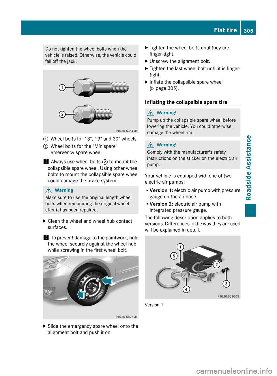
:Wheel bolts for 18", 19" and 20" wheels2Wheel bolts for the "Minispare"
emergency spare wheel
! Always use wheel bolts ; to mount the
collapsible spare wheel. Using other wheel
bolts to mount the collapsible spare wheel
could damage the brake system.
GWarning
Make sure to use the original length wheel
bolts when remounting the original wheel
after it has been repaired.
XClean the wheel and wheel hub contact
surfaces.
! To prevent damage to the paintwork, hold
the wheel securely against the wheel hub
while screwing in the first wheel bolt.
XSlide the emergency spare wheel onto the
alignment bolt and push it on.
XTighten the wheel bolts until they are
finger-tight.
XUnscrew the alignment bolt.XTighten the last wheel bolt until it is finger-
tight.
XInflate the collapsible spare wheel
(Y page 305).
Inflating the collapsible spare tire
GWarning!
Pump up the collapsible spare wheel before
lowering the vehicle. You could otherwise
damage the wheel rim.
GWarning!
Comply with the manufacturer's safety
instructions on the sticker on the electric air
pump.
Your vehicle is equipped with one of two
electric air pumps:
RVersion 1: electric air pump with pressure
gauge on the air hose.
RVersion 2: electric air pump with
integrated pressure gauge.
The following description applies to both
versions. Differences in the way they are used
will be explained in detail.
Version 1
Flat tire305Roadside AssistanceBA 251 USA, CA Edition A 2011; 1; 3, en-USd2sboikeVersion: 3.0.3.52010-04-16T14:31:55+02:00 - Seite 305Z
Page 308 of 364
Version 2
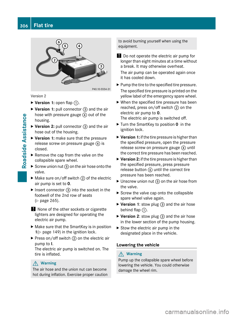
XVersion 1: open flap :.XVersion 1: pull connector = and the air
hose with pressure gauge ? out of the
housing.XVersion 2: pull connector = and the air
hose out of the housing.XVersion 1: make sure that the pressure
release screw on pressure gauge ? is
closed.XRemove the cap from the valve on the
collapsible spare wheel.XScrew union nut A on the air hose onto the
valve.XMake sure on/off switch ; of the electric
air pump is set to 0.XInsert connector 3 into the socket in the
footwell of the 2nd row of seats
( Y page 265).
!
None of the other sockets or cigarette
lighters are designed for operating the
electric air pump.
XMake sure that the SmartKey is in position
1 (Y page 149) in the ignition lock.XPress on/off switch ; on the electric air
pump to I.
The electric air pump is switched on. The
tire is inflated.GWarning
The air hose and the union nut can become
hot during inflation. Exercise proper caution
to avoid burning yourself when using the
equipment.
! Do not operate the electric air pump for
longer than eight minutes at a time without
a break. It may otherwise overheat.
The air pump can be operated again once
it has cooled down.XPump the tire to the specified tire pressure.
The specified tire pressure is printed on the
yellow label of the emergency spare wheel.XWhen the specified tire pressure has been
reached, press on/off switch 2 on the
electric air pump to 0.
The electric air pump is switched off.XTurn the SmartKey to position 0 in the
ignition lock.XVersion 1: if the tire pressure is higher than
the specified pressure, open the pressure
release screw on pressure gauge 4 until
the correct tire pressure has been reached.XVersion 2: if the tire pressure is higher than
the specified pressure, press pressure
release button 6 until the correct tire
pressure has been reached.XUnscrew union nut A on the air hose from
the valve.XScrew the valve cap onto the collapsible
spare wheel valve again.XVersion 1 : stow plug = and the air hose
behind flap :.XVersion 2 : stow plug = and the air hose
in the lower section of the pump housing.XStow the electric air pump in the
designated place in the vehicle.
Lowering the vehicle
GWarning
Pump up the collapsible spare wheel before
lowering the vehicle. You could otherwise
damage the wheel rim.
306Flat tireRoadside Assistance
BA 251 USA, CA Edition A 2011; 1; 3, en-USd2sboikeVersion: 3.0.3.52010-04-16T14:31:55+02:00 - Seite 306
Page 309 of 364
XPlace the ratchet ring spanner onto the
hexagon nut of the jack so that the letters
AB are visible.XTurn the ratchet ring spanner until the
vehicle is once again standing firmly on the
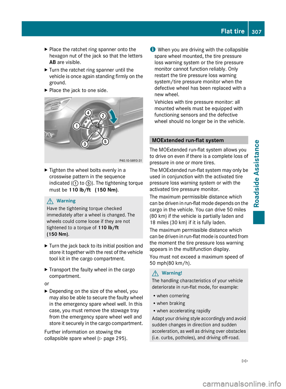
ground.XPlace the jack to one side.XTighten the wheel bolts evenly in a
crosswise pattern in the sequence
indicated ( : to A). The tightening torque
must be 110 lb/ft (150 Nm) .GWarning
Have the tightening torque checked
immediately after a wheel is changed. The
wheels could come loose if they are not
tightened to a torque of 110 lb/ft
(150 Nm) .
XTurn the jack back to its initial position and
store it together with the rest of the vehicle
tool kit in the cargo compartment.XTransport the faulty wheel in the cargo
compartment.
or
XDepending on the size of the wheel, you
may also be able to secure the faulty wheel
in the emergency spare wheel well. In this
case, you must remove the stowage tray
from the emergency spare wheel well and
store it securely in the cargo compartment.
Further information on stowing the
collapsible spare wheel ( Y page 295).
i
When you are driving with the collapsible
spare wheel mounted, the tire pressure
loss warning system or the tire pressure
monitor cannot function reliably. Only
restart the tire pressure loss warning
system/tire pressure monitor when the
defective wheel has been replaced with a
new wheel.
Vehicles with tire pressure monitor: all
mounted wheels must be equipped with
functioning sensors and the defective
wheel should no longer be in the vehicle.
MOExtended run-flat system
The MOExtended run-flat system allows you
to drive on even if there is a complete loss of
pressure in one or more tires.
The MOExtended run-flat system may only be
used in conjunction with the activated tire
pressure loss warning system or with the
activated tire pressure monitor.
The maximum permissible distance which
can be driven in run-flat mode depends on the
cargo in the vehicle. You can drive 50 miles
(80 km) if the vehicle is partially laden and
18 miles (30 km) if it is fully laden.
The maximum permissible distance which
can be driven in run-flat mode is counted from
the moment the tire pressure loss warning
appears in the multifunction display.
You must not exceed a maximum speed of
50 mph(80 km/h).
GWarning!
The handling characteristics of your vehicle
deteriorate in run-flat mode, for example:
R when cornering
R when braking
R when accelerating rapidly
Adapt your driving style accordingly and avoid
sudden changes in direction and sudden
acceleration, as well as driving over obstacles
(i.e. curbs, potholes), and driving off-road.
Flat tire307Roadside AssistanceBA 251 USA, CA Edition A 2011; 1; 3, en-USd2sboikeVersion: 3.0.3.52010-04-16T14:31:55+02:00 - Seite 307Z
Page 310 of 364
This is particularly the case when the vehicle
is heavily laden.
The maximum permissible distance that can
be driven in run-flat mode depends to a large
extent on the loads placed on the vehicle. It
can be shorter due to high speeds, a heavy
cargo, sudden changes in direction, the road
surface condition, outside temperature, etc.,
or further if you drive carefully and
conservatively.
Do not continue to drive in run-flat mode if:
Ryou hear banging noises.
Rthe vehicle starts to shake.
Ryou see smoke and smell rubber.
RESP® is intervening constantly.
Rthere are tears in the sidewalls of the tire.
After driving in run-flat mode, you must have
the wheel(s) checked for damage at a
qualified specialist workshop which has the
necessary specialist knowledge and tools to
carry out the work required. The faulty tire
must be replaced in every case.
Mercedes-Benz recommends that you use an
authorized Mercedes-Benz Center for this
purpose. In particular, work relevant to safety
or on safety-related systems must be carried
out at a qualified specialist workshop.
iWhen replacing one or all tires, make sure
that you only use tires marked
MOExtended and of the specified size for
the vehicle.
iVehicles featuring the MOExtended run-
flat system are not equipped with TIREFIT
kit at the factory. It is therefore
recommended that you additionally equip
your vehicle with the TIREFIT kit if you
mount tires that do not feature run-flat
properties, e.g. winter tires. You can obtain
a TIREFIT kit from an authorized Mercedes-
Benz Center, for example.
Battery
Important safety guidelines
In order for the battery to achieve the
maximum possible service life, it must always
be sufficiently charged.
! Have the battery checked regularly at a
qualified specialist workshop, e.g. an
authorized Mercedes-Benz Center.
Observe the service intervals in the Service
Booklet or for further information consult a
qualified specialist workshop, e.g. an
authorized Mercedes-Benz Center.
Have the battery charge checked more
frequently if you use the vehicle mainly for
short trips or if you leave it standing idle for
a lengthy period.
To prevent damage from corrosion, only
replace the battery with one that has a central
ventilation cover.
Only replace a battery with a battery that has
been recommended by Mercedes-Benz.
Consult an authorized Mercedes-Benz Center
if you wish to leave your vehicle parked for a
long period of time.
GWarning!
Comply with safety precautions and take
protective measures when handling batteries.
Risk of explosionFire, naked flames and
smoking are prohibited
when handling the battery.
Avoid creating sparks.
Battery acid is caustic.
Avoid contact with the skin,
eyes or clothing.
Wear suitable protective
clothing, in particular
gloves, an apron and a face
mask.
308BatteryRoadside Assistance
BA 251 USA, CA Edition A 2011; 1; 3, en-USd2sboikeVersion: 3.0.3.52010-04-16T14:31:55+02:00 - Seite 308