fuse MERCEDES-BENZ R-CLASS FAMILY TOURER 2013 Owners Manual
[x] Cancel search | Manufacturer: MERCEDES-BENZ, Model Year: 2013, Model line: R-CLASS FAMILY TOURER, Model: MERCEDES-BENZ R-CLASS FAMILY TOURER 2013Pages: 364, PDF Size: 28.68 MB
Page 13 of 364
Fue
lgauge ....................................... 31
Grade (gasoline) ............................ 351
Important safety notes ..................351
Premium-grade unleaded gasoline .351
Problem (malfunction) ...................163
Quality (diesel). .............................. 352
Refueling ........................................ 160
Tank content/reserve fuel .............351
Fuel filler flap
Emergency release ........................162
Opening/closing ............................ 161
Fuel filte r(display message) ............227
Fuel level Calling up the range (on-board
computer) ...................................... 212
Fuel tank
Capacity ........................................ 351
Problem (malfunction) ...................163
Fuse allocation chart (vehicle tool
kit) ...................................................... 299
Fuses Allocation chart ............................. 309
Before changing ............................. 309
Dashboard fuse box .......................309
Engine emergency stop .................310
Fuse box in the cargo
compartment ................................. 310
Fuse box in the engine
compartment ................................. 309
Important safety notes ..................308 G
Garage door opener Clearing the memory .....................280
Important safety notes ..................277
Opening/closing the garage door ..280
Programming (button in the rear-
view mirror) ................................... 278
Genuine Mercedes-Benz parts .........348
Glove box ........................................... 251
GTW (Gross Trailer Weight)
(definition) ......................................... 332 H
Handbrake see Parking brake
Hazard warning lamps ......................124
Headlamp delayed switch-off see Exterior lighting delayed switch-off
Headlamps
Adding fluid to cleaning system .....288
Cleaning system (capacity )............ 356
Cleaning system (function) ............123
Cleaning system (notes) ................356
Fogging up ..................................... 124
see Automatic headlamp mode
Head restraints
Adjusting ....................................... 103
Adjusting (electrically). ..................103
Adjusting (manually). .....................103
Adjusting (rear) .............................. 104
Installing/removing (rear) ..............104
Luxury ............................................ 103
see NECK-PRO head restraints/
NECK-PRO luxury head restraints
Heating
see Climate control
High-beam headlamps
Changing bulbs .............................. 128
Display message ............................ 222
Switching on/off ........................... 123
Hill start assist .................................. 152
Hood Closing .......................................... .285
Display message ............................ 235
Opening ......................................... 284
Hydroplaning ..................................... 171 I
Ignition lock see Key positions
Immobilizer .......................................... 72
Indicator and warning lamps DISTRONI C.................................... 246
Indicator lamps
see Warning and indicator lamps
Insectp rotection on the radiator ....285 10
Index
Page 98 of 364
Resetting
!
If the sliding sunroof still canno tbe
opened or closed fully after resetting,
contact a qualified specialist workshop.
Reset the sliding sunroof if it does not move
smoothly, or if the battery has been
disconnected or has become discharged.
X Remove the SmartKey from the ignition
lock or turn it to position 0(KEYLESS-GO).
X Remove the fuse for the sliding sunroof
from the fuse box. To find out where the
fuse is located, refer to the fuse allocation
chart in the vehicle tool kit (Y page 298).
X Reinsert the fuse.
X Turn the SmartKey to position 2in the
ignition lock.
X Raise the sliding sunroof fully at the rear
(Y page 94).
X Keep the 2switch pressed for another
second.
X Make sure that the sliding sunroof can be
fully opened and closed again (Y page 94).
X If this is not the case, repeat the steps
above again. Operating the panorama roof with
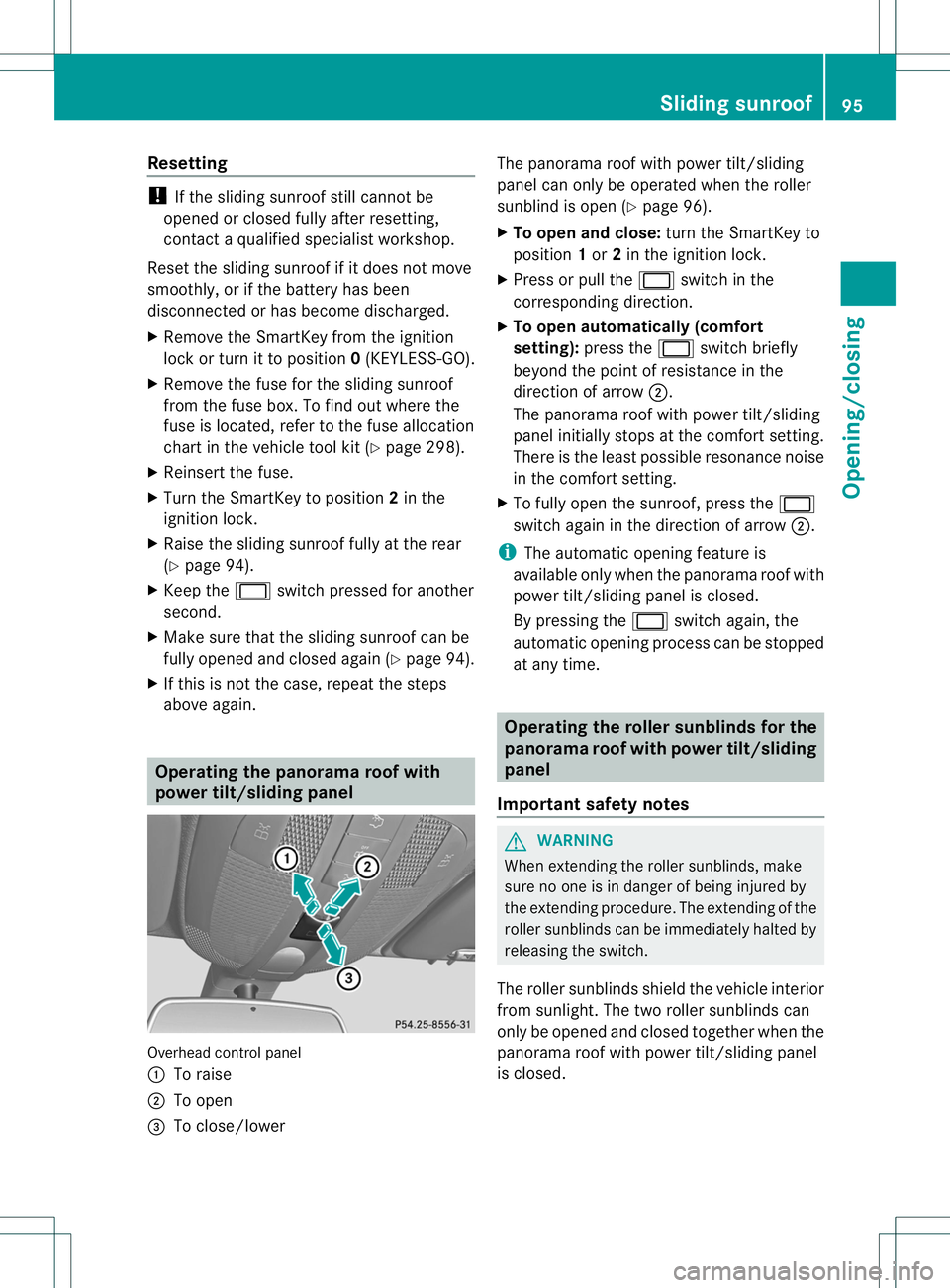
power tilt/sliding panel
Overhead control panel
:
To raise
; To open
= To close/lower The panorama roof with power tilt/sliding
panel can only be operated when the roller
sunblind is open (Y
page 96).
X To open and close: turn the SmartKey to
position 1or 2in the ignition lock.
X Press or pull the 2switch in the
corresponding direction.
X To open automatically (comfort
setting): press the 2switch briefly
beyond the point of resistance in the
direction of arrow ;.
The panorama roof with power tilt/sliding
panel initially stops at the comfor tsetting.
There is the least possible resonance noise
in the comfort setting.
X To fully open the sunroof ,press the 2
switch again in the direction of arrow ;.
i The automatic opening feature is
available only when the panorama roof with
power tilt/sliding panel is closed.
By pressing the 2switch again, the
automatic opening process can be stopped
at any time. Operating the roller sunblinds for the
panorama roof with powe
rtilt/sliding
panel
Important safety notes G
WARNING
When extending the roller sunblinds, make
sure no one is in danger of being injured by
the extending procedure. The extending of the
roller sunblinds can be immediately halted by
releasing the switch.
The roller sunblinds shield the vehicle interior
from sunlight. The two roller sunblinds can
only be opened and closed together when the
panorama roof with power tilt/sliding panel
is closed. Sliding sunroof
95Opening/closing Z
Page 272 of 364
Note that the socket in the cigarette lighter
can be damaged when connecting
accessories, for example by:
R
frequent insertion and removal
R sockets that do not fit correctly
Ad amaged socke tcan cause the cigarette
lighter to stop working.
! The cigarette lighter in the cente rconsole
in the front compartment is not intended
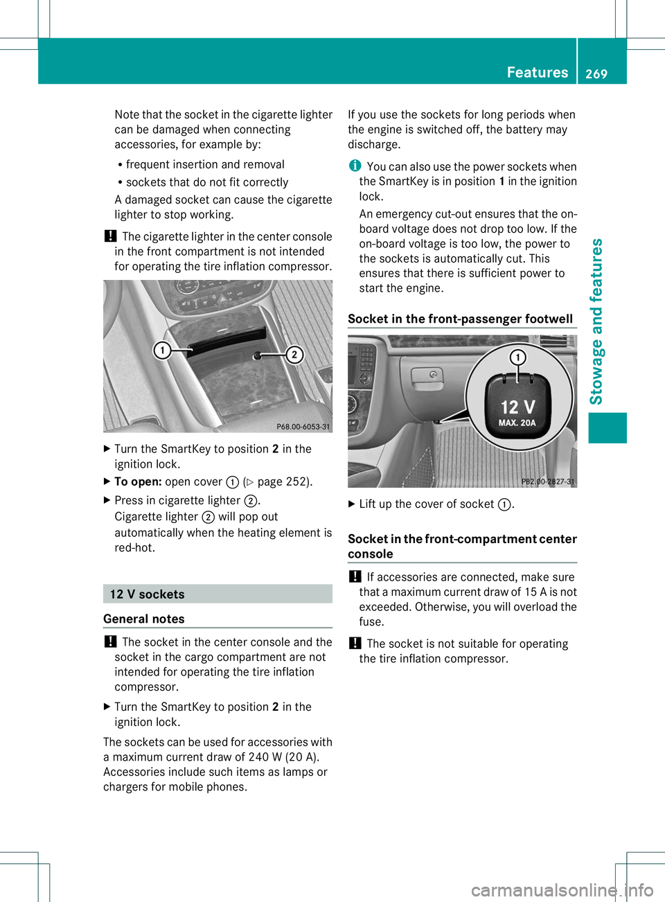
for operating the tire inflation compressor. X
Turn the SmartKey to position 2in the
ignition lock.
X To open: open cover :(Ypage 252).
X Press in cigarette lighter ;.
Cigarette lighter ;will pop out
automatically when the heating element is
red-hot. 12
Vsockets
General notes !
The socket in the center console and the
socket in the cargo compartment are not
intended for operating the tire inflation
compressor.
X Turn the SmartKey to position 2in the
ignitio nlock.
The sockets can be used for accessories with
a maximum current draw of 240 W (20 A).
Accessories include such items as lamps or
chargers for mobile phones. If you use the sockets for long periods when
the engine is switched off, the battery may
discharge.
i
You can also use the power sockets when
the SmartKey is in position 1in the ignition
lock.
An emergency cut-out ensures that the on-
board voltage does not drop too low. If the
on-board voltage is too low, the power to
the sockets is automatically cut. This
ensures that there is sufficient power to
start the engine.
Socket in the front-passenger footwell X
Lift up the cover of socket :.
Socket in the front-compartment center
console !
If accessories are connected, make sure
that amaximum curren tdraw of 15 A is not
exceeded. Otherwise, you willo verload the
fuse.
! The socket is not suitable for operating
the tire inflation compressor. Features
269Stowage and features Z
Page 273 of 364
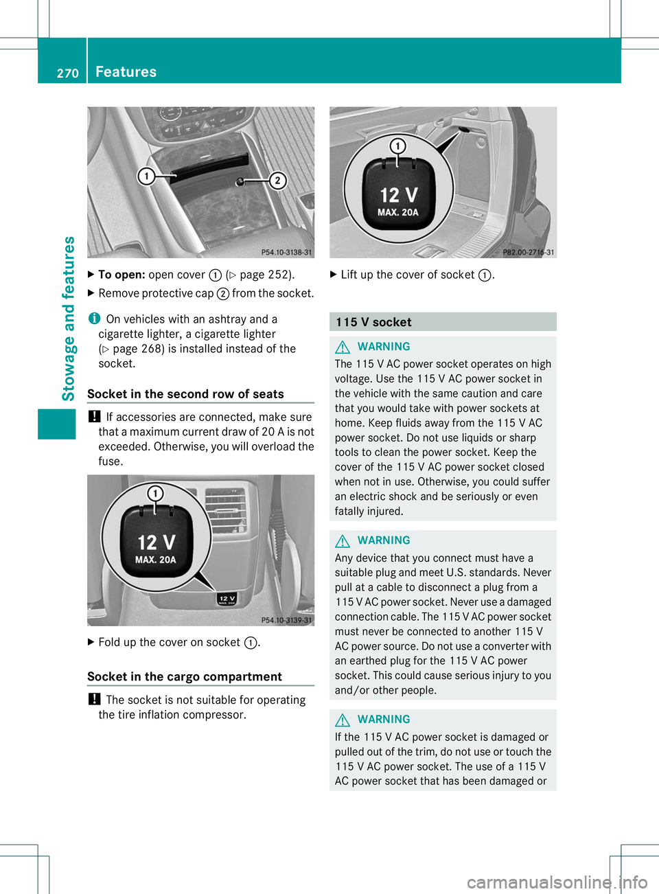
X
To open: open cover :(Ypage 252).
X Remove protective cap ;from the socket.
i On vehicles with an ashtra yand a
cigarette lighter, a cigarette lighter
(Y page 268) is installe dinstead of the
socket.
Socket in the second row of seats !
If accessories are connected, make sure
that amaximum curren tdraw of 20 A is not
exceeded. Otherwise, you willo verload the
fuse. X
Fold up the cover on socket :.
Socket in the cargo compartment !
The socket is not suitable for operating
the tire inflation compressor. X
Lift up the cover of socket :. 115
Vsocket G
WARNING
The 11 5VAC powe rsocket operates on high
voltage. Use the 115 V AC power socket in
the vehicle with the same caution and care
that you would take with power sockets at
home. Keep fluids away from the 115 V AC
power socket .Do not use liquids or sharp
tools to clean the power socket .Keep the
cover of the 115 V AC power socket closed
when not in use. Otherwise, you could suffer
an electric shock and be seriously or even
fatally injured. G
WARNING
Any device that you connect must have a
suitable plug and meet U.S.s tandards.Never
pull at a cable to disconnect a plug from a
115 VAC power socket. Never use a damaged
connection cable. The 11 5VAC power socket
must never be connected to another 115 V
AC power source. Do no tuse a converter with
an earthed plug for the 115 V AC power
socket. This could cause serious injury to you
and/or other people. G
WARNING
If the 115 V AC power socket is damaged or
pulled out of the trim, do not use or touch the
115 V AC power socket. The use of a 115 V
AC power socket that has been damaged or 270
FeaturesStowage and features
Page 300 of 364
Useful information
............................298
Where will I find...? ...........................298
Flat tire .............................................. 299
Battery( vehicle)................................ 301
Jump-starting .................................... 304
Towing and tow-starting ..................306
Fuses .................................................. 308 297Breakdown assistance
Page 302 of 364
X
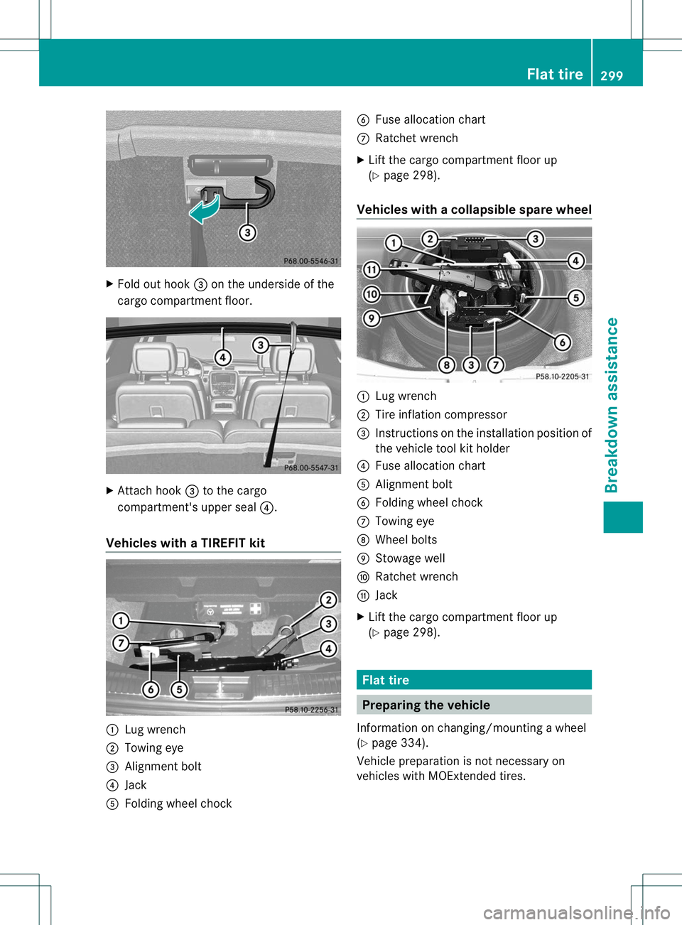
Fold ou thook =on the underside of the
cargo compartment floor. X
Attach hook =to the cargo
compartment's upper seal ?.
Vehicles with aTIREFIT kit :
Lug wrench
; Towing eye
= Alignmen tbolt
? Jack
A Folding wheel chock B
Fuse allocation chart
C Ratchet wrench
X Lift the cargo compartment floor up
(Y page 298).
Vehicles with acollapsible spare wheel :
Lug wrench
; Tire inflatio ncompressor
= Instructions on the installation position of
the vehicle tool kit holder
? Fuse allocation chart
A Alignmen tbolt
B Folding wheel chock
C Towing eye
D Wheel bolts
E Stowage well
F Ratchet wrench
G Jack
X Lift the cargo compartment floor up
(Y page 298). Flat tire
Preparing the vehicle
Information on changing/mounting a wheel
(Y page 334).
Vehicle preparation is not necessary on
vehicles with MOExtended tires. Flat tire
299Breakdown assistance
Page 311 of 364
X
Leave the SmartKey in position 2in the
ignition lock.
X Switch on the hazard warning lamps
(Y page 124).
i In order to signal a change of direction
when towing the vehicle with the hazard
warning lamps switched on, use the
combination switch as usual. In this case,
only the turn signals for the desired
direction flash.W hen you reset the
combination switch, the hazard warning
lamps start flashing again. Transporting the vehicle
! Only lash the vehicle down by the wheels
or wheel rims, not by parts of the vehicle
such as axle or steering components.
Otherwise, the vehicle could be damaged.
The towing eyes or trailer tow hitch can be
used to pull the vehicle onto a trailer or
transporter if you wish to transport it.
X Turn the SmartKey to position 2in the
ignition lock.
X Shift the automatic transmission to
position N.
As soon as the vehicle is loaded:
X Prevent the vehicle from rolling away by
applying the parking brake.
X Shift the automatic transmission to
position P.
X Turn the SmartKey to position 0in the
ignition lock and remove it.
X Secure the vehicle. Information on 4MATIC vehicles
! Vehicles with 4MATIC must not be towed
with either the front or the rear axle raised,
as doing so will damage the transmission.
If the vehicle has transmission damage or
damage to the front or rear axle, have it
transported on a transporter or trailer. In the event of damage to the electrical
system
If the battery is defective, the automatic
transmission will be locked in position
P. To
shift the automatic transmission to position
N, you must provide power to the vehicle's
electrical system in the same way as when
jump-starting (Y page 304).
Have the vehicle transported on a transporter
or trailer. Recovering
avehicle that has become
stuck
! Pull away smoothly, slowly, and in a
straigh tline when pulling out a vehicle that
has become stuck. Excessive tractive
power could damage the vehicles.
If the drive wheels get trapped on loose or
muddy ground, recover the vehicle with the
utmost care, especially so if the vehicle is
laden.
Never attempt to recover a vehicle with a
trailer attached.
Pull out the vehicle backwards, if possible,
using the tracks it made when it became
stuck. Tow-starting (emergency starting)
! Vehicles with an automatic transmission
must not be tow-started. You could
otherwise damage the automatic
transmission.
You can find information on "Jump-starting"
at (Y page 304). Fuses
Important safety notes
G
WARNING
Only use fuses that have been approved for
Mercedes-Ben zvehicles and that have the
correct fuse rating for the systems 308
FusesBreakdown assistance
Page 312 of 364
concerned. Do not attempt to repai
rorbridge
faulty fuses .Using fuses that have not been
approved or attempting to repair or bridge
faulty fuses could cause the fuse to be
overloaded and result in afire. Have the cause
traced and rectified at a qualified specialist
workshop.
! Only use fuses that have been approved
for Mercedes-Ben zvehicles and which
have the correct fuse rating for the system
concerned. Otherwise, components or
systems could be damaged.
The fuses in your vehicle serve to close down
faulty circuits. If afuse blows, all the
components on the circuit and their functions
stop operating.
Blown fuses must be replace dwith fuses of
the same rating, which you can recognize by
the color and value. The fuse ratings are listed
in the fuse allocation chart.
If a newly inserted fuse also blows, have the
cause traced and rectified at a qualified
specialist workshop, e.g. an authorized
Mercedes-Ben zCenter. Before changing a fuse
X Secure the vehicle against rolling away
(Y page 166).
X Switch off all electrical consumers.
X Turn the SmartKey to position 0in the
ignition lock and remove it (Y page 149).
On vehicles with KEYLESS-GO, make sure
the ignition is switched off (Y page 149).
All indicator lamps in the instrument cluster
must be off.
The fuses are located in various fuse boxes:
R fuse box on the front-passenger side of the
dashboard
R fuse box in the engine compartment on the
right-hand side of the vehicle, when viewed
in the direction of travel
The fuse allocation chart is in the vehicle tool
kit which is located in the stowage compartment under the cargo compartment
floor (Y
page 298). Dashboard fuse box
! Do not use a pointed objec tsuch as a
screwdriver to open the cover in the
dashboard. You could damage the
dashboard or the cover.
! Make sure that no moisture can ente rthe
fuse box when the cover is open.
! When closing the cover, make sure that it
is lying correctly on the fuse box. Moisture
seeping in or dirt could otherwise impair
the operation of the fuses. X
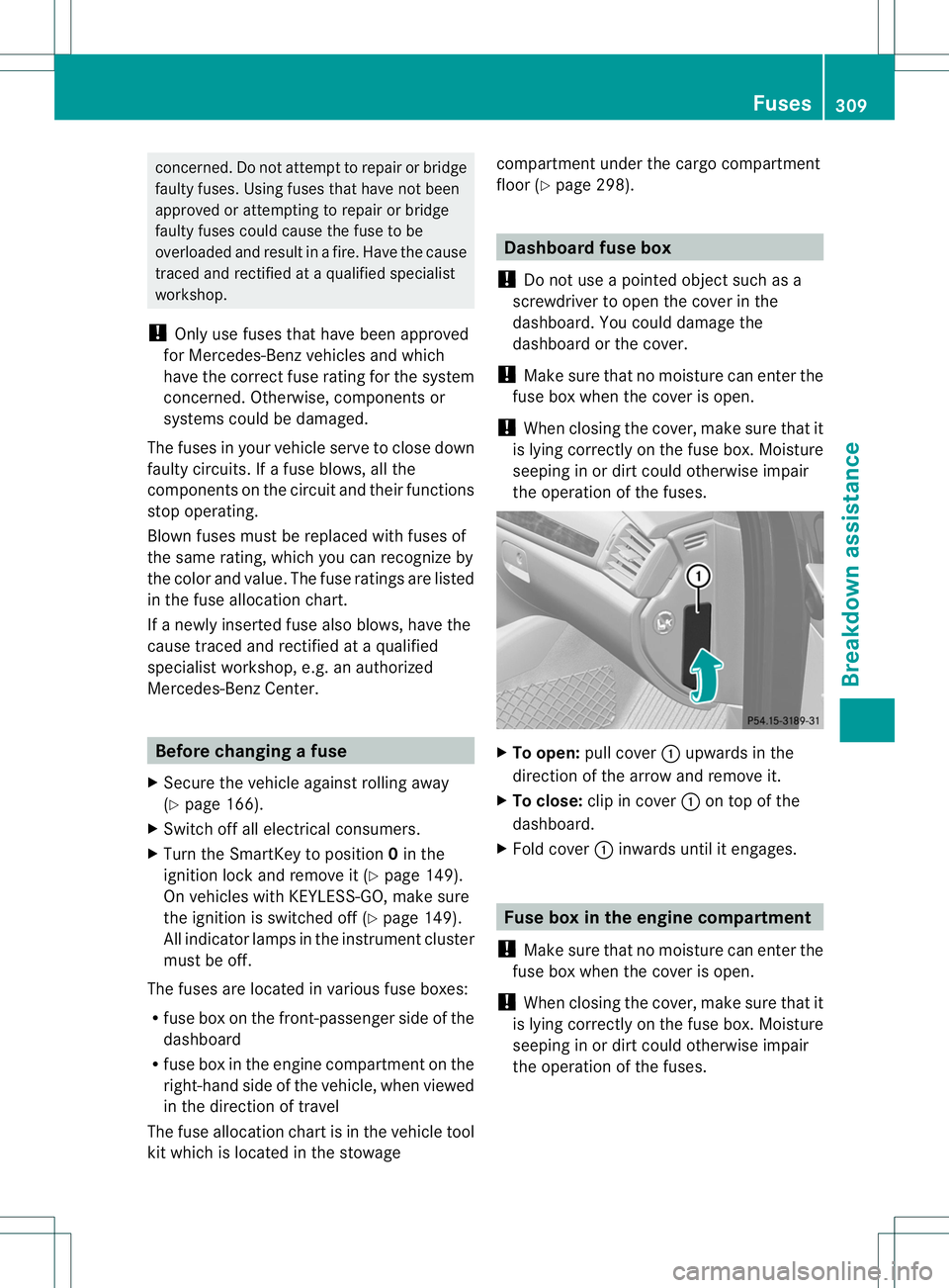
To open: pull cover :upwards in the
direction of the arrow and remove it.
X To close: clip in cover :on top of the
dashboard.
X Fold cover :inwards until it engages. Fuse box in the engine compartment
! Make sure that no moisture can enter the
fuse box when the cover is open.
! When closing the cover, make sure that it
is lying correctly on the fuse box. Moisture
seeping in or dirt could otherwise impair
the operation of the fuses. Fuses
309Breakdown assistance Z
Page 313 of 364
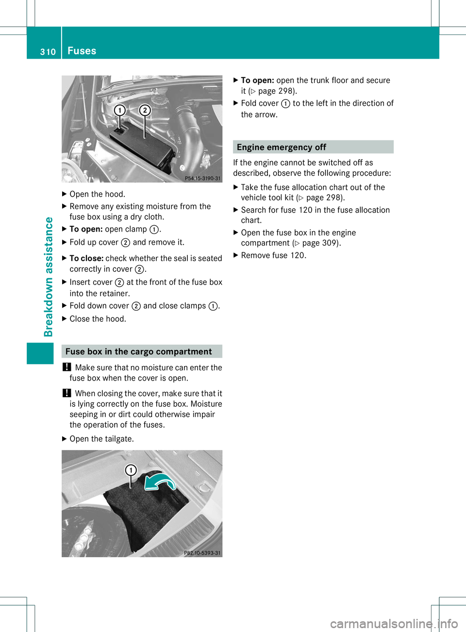
X
Open the hood.
X Remove any existing moisture from the
fuse box using a dry cloth.
X To open: open clamp :.
X Fold up cover ;and remove it.
X To close: check whether the seal is seated
correctly in cover ;.
X Insert cover ;at the front of the fuse box
into the retainer.
X Fold down cover ;and close clamps :.
X Close the hood. Fuse box in the cargo compartment
! Make sure that no moisture can enter the
fuse box when the cover is open.
! When closing the cover, make sure that it
is lying correctly on the fuse box. Moisture
seeping in or dirt could otherwise impair
the operation of the fuses.
X Open the tailgate. X
To open: open the trunk floor and secure
it (Y page 298).
X Fold cover :to the left in the direction of
the arrow. Engine emergency off
If the engine cannot be switched off as
described, observe the following procedure:
X Take the fuse allocation chart out of the
vehicle tool kit (Y page 298).
X Search for fuse 120 in the fuse allocation
chart.
X Open the fuse box in the engine
compartment (Y page 309).
X Remove fuse 120. 310
FusesBreakdown assistance